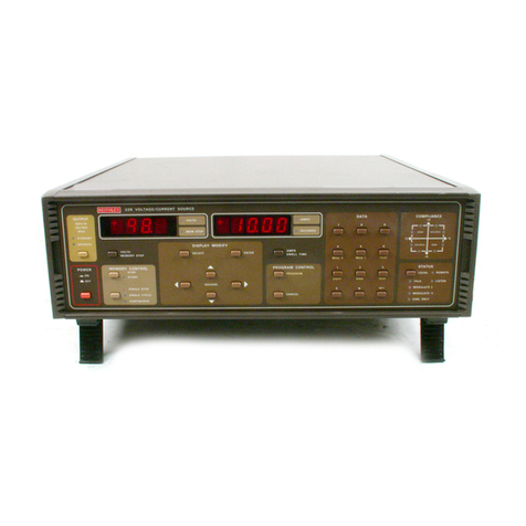
OPERATION MODEL 244 HIGH VOLTAGE SUPPLY
SECTION 2. OPERATION
2-1. CONNECTIONS.
a. Output Receptacle.- A rear panel mounted MHV
teflon-insulated receptacle provides connection to
the load circuit. The outer shell of the receptacle
is connected to chassis.
b. Coaxial Cables.- Use coaxial cables which are
rated for greater than 2200 volts for safe operation.
Coaxial cables provide best noise immunity for criti-
cal meaeurements.
C. Earth Ground.- For maximum operator safety use
the 3-wire power cord with third wire solidly connec-
ted to earth ground.
2-2. PRELIMINARY PROCEDURES.
a. The instrument is shipped in operating condition
+ith all components installed for immediate use.
b. Set the 117-234 volt switch for operating line
voltage.
C. Check the fuse for proper type and rating.
d. Provide adequate ventilation for the instrument.
Air flow should be maintained along the top and bottom
surfaces.
NOTE
If air flow is constricted the internal
temperature will rise above normal design
limits causing degradation of critical
components.
e. Set the front panel controls as follows:
POWERSwitch Off
Voltage Dials 2-o-o
OUTPUT Switch Off
f. Connect the line cord and set the POWER
Switch to ON. (The POWERindicator should
be lighted.)
NOTE
The meter should indicate 0 KILOVOLTS.
g. After a preliminary one minute warmup period,
p&ace the OUTPUT Switch to ON position. Allow another
warmup period (30 minutes) for the high voltage sec-
tion to stabilize. The meter should indicate approx-
imately one minor division or 200 volts.
2-3. OPERATING CHECK-OUT.
a. Meter Indication.- When the OUTPUT Switch is ON
the meter should indicate the dialed voltage.
b. Output Voltage.- Connect an accurate voltmeter
such as Keithley Model 153 to the output to verify
the power supply voltage accuracy. The Trim Control
should be set to CAL position. measure the Model 244
output for dial settings of 200,,,500, and 1000 volts.
Accuracy should be 21% of dial setting.
c. Current Limit.- (Refer also to paragraph 2-5
for a more complete discussion of the overload current
operation.)
1. Connect an accurate ammeter such as a Keith-
ley Model 153 in series with an adjustable resis-
tance decade box. Set the dialed voltage on the
Model 244 at -200 volts with the OUTPUT Switch
"OFF". Apply the -200 volt output to the resistance
decade box set at 20 kilahms. The ammeter should
indicate 10 mA when the OUTPUT Switch is placed
nON". The OVERLOADIndicator should not be lighted.
Decrease the resistance load until the OVERLOADIn-
dicator is lighted. The annneter should indicate
between 11 mA and 12 n!A.
NOTE
Resistor load power dissipation is approx-
imately 2.2 Watts.
2. Connect an ammeter and 50 kilohm resistive
load to the output of the Model 244. Set the dial-
ed voltage an the Model 244 at -200 volts with the
OUTPUT Switch "OFF". Place the OUTPUT Switch to
"ON" position. Reduce the load to zero ohms (short
circuit) and measure the output current. The
ammeter should indicate less than 14 milliamperes
with the Model 244 OVERLOADIndicator lighted.
2-4. SETTING OUTPUT VOLTAGE. The setting of the
Voltage Dials and Trim Control determines the magni-
tude of the output.
a. The two Voltage Diala set the output from -200
to -2200 volts d-c in calibrated 200 and 20-volt
steps. With the Trim Control in CAL position the
output is set by the Voltage Dials within specified
kXC"K%Y.
b. The Trim Control interpolates between 20-volt
settings with 100 millivolt resolution. The Trim
Control range is 0 to 25 volts.
4 0770

