Kelant S400S User manual

S400S
3D PRINTER
PRODUCT MANUAL
S400S-3D printer User Manual
Shenzhen kelant science and technology Co., Ltd.

Thank you choosing Kelant Combat S400S printer!
If you have any questions, please contact
customer service or log on the official website
www.kelandi.cn
Facebook group:
https://www.facebook.com/groups/KelantOfficial
Copyrighted by “shenzhen Kelant Technology co.,Ltd”All rights reserved

1、Packing List...................................................................................................................................... 1
2. Precautions..................................................................................................................................... 2
3、Technical Specification............................................................................................................. 3
4、Printer Overview........................................................................................................................... 4
5、Assembling....................................................................................................................................... 5
6、Touch screen Introduction..................................................................................................... 9
7、Menu directory.............................................................................................................................. 9
8、Leveling ............................................................................................................................................11
9、Slice software description ....................................................................................................14
10、First print instructions..........................................................................................................22
11、FAQ and machine maintenance..................................................................................... 24

1
1、Packing List
Kelant S400S 1PCS
Z axis 1PCS
Resin Vat 1PCS
Handle 1PCS
Hinge 2PCS
Cover 5PCS
Cover pillar
8PCS
Platform Base
1PCS
Screws 5PCS
Hand screw
1PCS
Power adapter
1PCS
Build Plate 1PCS

2
2.Precautions
Please contact customer service if you have any questions after you
received the printer
Keep the Kelant combat S400S and its accessories away from Children
Use printer at room temperature , Avoid direct sunlight and dusty
environment
Kelant Combat S400S must NOT be exposed to water and rain.
Wear gloves when handling resin and avoid direct skin contac
Be cautious when using the scarper . Never direct the scraper
towards you.
Few accessories in Kelant Combat S400S printer are consumables and the
warranty coverage may vary
Do not disassemble Kelant Combat S400S printer,Please contact
technical support if you have any questions .
In case of emergency ,Please immediately cut off the power of Kelant
Combat S400S printer and contact technical support .

3
3、Technical Specification
Printing parameters
System Kelant
Operation 3.5-inch touch screen
Slicing software ChiTu DLP Slicer/ChiTuBox
Connectivity USB Disk
Specifications
Technique LCD Shadow Masking
Light Source UV-LED(Wavelength 405nm)
XY Resolution 75 microns(2560*1600)
Z axis accuracy 25 microns
Suggested layer thickness 0.025~0.2mm
Print speed 30mm/h
Rated power 144W
Physical Dimensions
Dimension 345mm(L)*300mm(W)*455mm(H)
Build Volume 190mm(L)*120mm(W)*200mm(H)
Material 405nm UV-resin
Weight ~17kg

4
4、Printer Overview
Acrylic
touch
screen
Screw rod
platform
Platform
Base Screw
USB interface
DC interface
Power switch
Resin Vat
Screw
Resin
Vat

5
5、Assembling
1、Place Printer base on the desktop.
2、Mount the Z-axis to the main unit as shown. (Materials required:
4 pcs screws ,M6*15 )
3、Lock the screw of the lead screw and the motor coupling and insert
the upper limit switch plug.

6
4、Take out the four B1, B2, and B3 columns. The groove on the column
is inserted into the main plate of the main unit in the direction
of the red arrow (if you can't insert it, loosen the machine screw
on the column) and lock the four columns. The machine screw shown
in the partial enlarged view (there are screws in the hole)
5、Remove the two acrylic A1, tear open the protective film on the
acrylic, and insert the groove on the machine from top to bottom
according to the blue arrow.
B1(2PCS)
B2(1PCS)
B3(1PCS)
A1(2PCS)

7
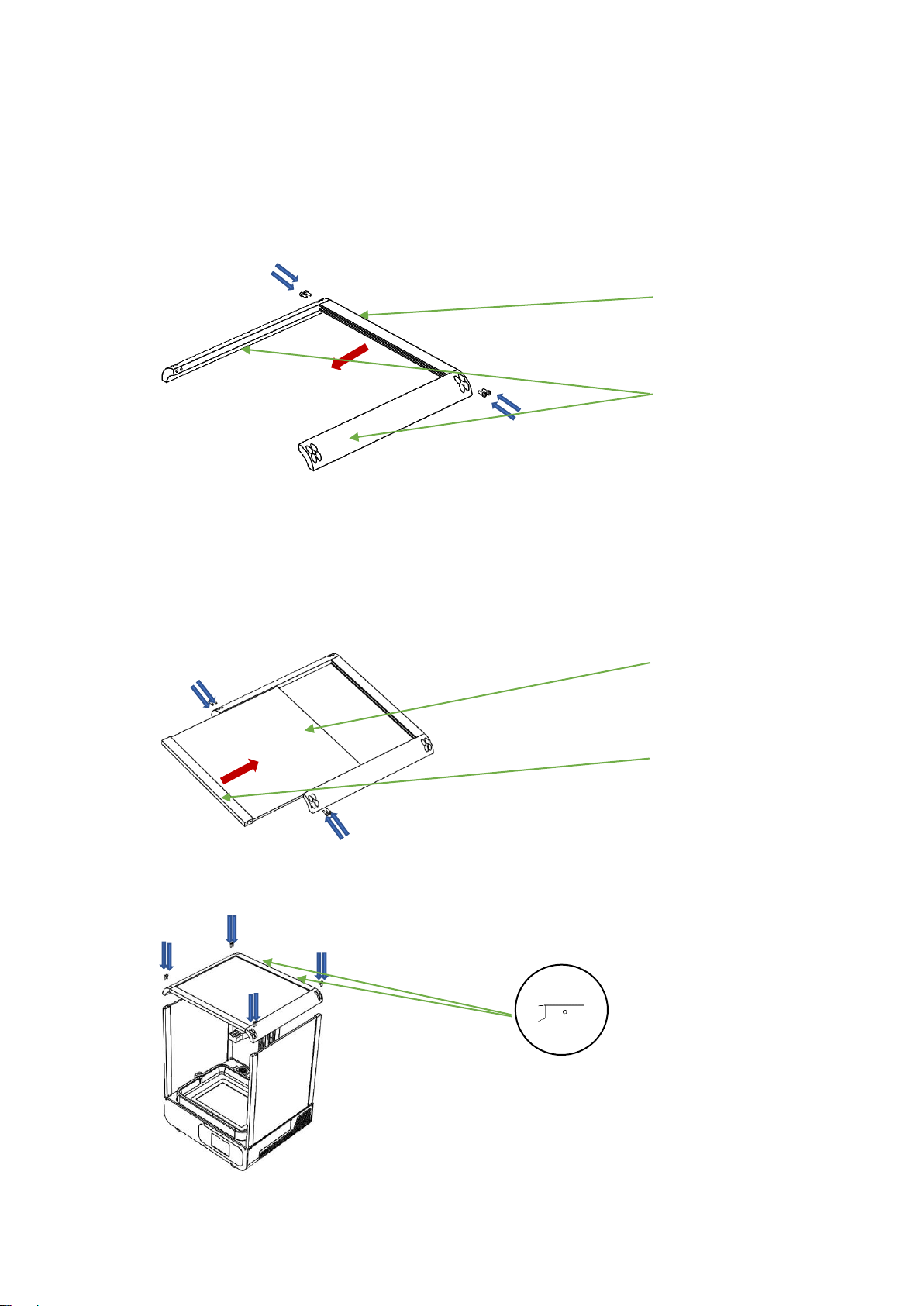
6、Remove the three B4 and B5 columns. The groove on the B4 column is
oriented in the direction shown by the red arrow. Use the four S1
screws to lock the three columns.
7、Remove the column B6, acrylic A2, and tear off the protective film
of the acrylic A2. Insert the groove of the B6 in the direction of
the red arrow and lock it with 4 S1 screws.
8、The assembled top cover is locked to the outer casing with 8 S1 screws
(the side with the screw holes facing backwards)
B4(1PCS)
B5(2PCS)
A2(1 PCS)
B6(1 PCS)

8
9、Remove the hardware kit fist, use one S2 screw to mount the
handle on the A4 board, four S3 screws will hinge on the B3 column,
and then use the six S4 screws to mount the acrylic A3.
10. To install the printing platform, first use six S2 screws (M4*10)
to pass through the platform plate, and then tighten the screws with
the pan/tilt side plates. Screw the hand screw into the head.
A3(1PCS)
A4(1PCS)
Handle(1PCS)
B3
Hinge(2PCS)
Hand screw
tilt side plates
Plate
screw

9
System
Print
Service
Network
print
Tool
Manual
Information
Calibrate and Full exposure
6、Touch screen Introduction
main menu

10
7、Menu directory
Service
Return to System Menu
Detection
Click to set the test time
Increase the test time
Reduce the test time
Click on the test for pre-set time
Return to tools Menu
System
Move Z-axis manually
Screen test
Re-set the zero point
Turn of Z-axis motor
Cleaning tank
Return to Home Menu
System
Change Language (Chinese/English )
Official website and after sale contact
Product information
Return to Home Menu
Move Z-axis
Move up Z-axis
Move down Z-axis
Return to Zero
Z-axis moves 0.1mm
Stop moving Z-axis
Return to Home Menu
Information
Turn on / off Sound
Return to system menu
Delete Current file
Click start printing
Return to print Menu
Enter the System Menu
Enter the tools Menu
Printing

11
7、Leveling
The machine has been leveled at the factory, and you
can print with the flatbed installed. If the printing
does not stick to the platform, please follow the steps
below to level
1、Take out the assembled printing platform and loosen the four screws
on the left and right sides of the cradle head, so that the cradle
head can move up and down freely. As shown in the picture.
2、Check and keep 2K LCD screen and platform clean No resin and no
impurities (foreign matter can be wiped with alcohol).
3、Turn on the machine's power switch.
4、Put an A4 paper on the 2K LCD screen, install the platform to the
platform bracket, and tighten the black platform fixing knob (as
shown).
5、As shown in the figure, click “Tool”→“Nanual”→“Home”on
the touch screen →wait for the Z-axis to descend and stop

12
automatically.
When the Z axis is down, if there is an abnormality, click "STOP" to stop
the drop.
6、Press the top of the platform with your hand, so that the four corners
of the platform are evenly attached to the 2K LCD screen. Tighten
the screws on the left and right sides of the cradle head diagonally,
and twitch the four corners of the A4 paper. The resistance is even
and uniform, otherwise the steps 1, 2, 3, 4, and 5 are repeated.
7、Finally, click “Tool”→“Nanual”→“UP”on the touch screen
again, move up the Z axis height, then return to zero, wait for the
zero to twitch and then draw A4 paper to see if there is obvious
resistance, whichever is greater. End adjustment of the Z-axis

13
height.
8、Upward platform about 100mm, check whether the LCD screen works
normally: as shown in the figure, press the touch screen "Tool" →
"calibrate" →"Next", if the 2K forming screen can display the grid
completely, it means the LCD screen works normally. ,as the picture
shows.
9、Install the resin Vat : Push the resin Vat into the bottom plate
and align it with the groove and trough on the middle plate. Finally,
tighten the two thumbscrews as shown.
Vat cap
Push into the trough

14
9、Slice software description
1、Installation instructions
The slicing software is located on the USB Drive, under the slicing
software folder Run the slicing software installer (double-click
the software icon). According to the following figure for installation:

15
2、Language Settings
Click the top left corner of the software interface, and click the
language to change the language Settings.
3、Import the configuration
Click on the upper left corner of the software interface, click help,
click Import configuration, select KLD-S400S.cfg. in the USB Drive folder
"切片软件 Slicer "

16
4、Introduction to slicing interface
Click "open file" → "select file" → "open" at the top of the
interface to import your own 3d format model (.stl file). Click the model
with the left mouse button, and change the position, placement Angle, zoom
in and zoom out of the model image by operating the function options on
the left side of the software interface。The menu bar at the top of the
software interface is respectively for opening files, saving files,
screen capture/recording, restoring, redoing, cloning the current model,
automatic layout, hollowing out, digging holes. On the right side of the
software interface are section Settings and support parameters。
Other operations:
(1)Position Change : Left click and hold on the model ,then you may change the
model position ,by dragging it around
(2)Zoom in / out : Scroll the mouse wheel
(3)Change viewing angle : right click the plateform .hold on and move on the
mouse .

17
5、Slice parameter setting
First click on the slicing settings of the software interface, and then
set the machine, resin, print, fill, Gcode, advanced settings, please
refer to the following figure::
Table of contents