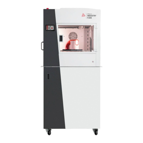
3DGence INDUSTRY F420 User manual

USER’S MANUAL
Translation of the original manual
3DGence INDUSTRY F420

page 1of 102
3DGence INDUSTRY F420 | version 10.2020
COPYRIGHT AND TRADEMARKS
The name 3DGence and its respective logo are trademarks or registered trademarks of 3DGence.
General information: other product names, if used in this document, are for identification purposes only and may be
trademarks of their respective owners.
DISCLAIMER
No part of this document may be reproduced, stored in a retrieval system, translated into another language or transmitted in
any form or by any means - electronic, mechanical or otherwise - without the prior written permission of 3DGence. All
information and drawings in this document are for the specific 3DGence printer only.
Neither 3DGence nor its affiliates, particularly those involved in the development, manufacture or delivery of this product,
shall be liable to the purchaser of this product or third parties for any damages (including, without limitation, incidental or
consequential damages, loss of profits, business interruption), or loss of business information) or expenses incurred by the
purchaser or a third party as a result of an accident, inappropriate or improper use of this product, unauthorised modifications
or repairs to this product, or failure to follow 3DGence's operating and maintenance instructions - even if 3DGence or its
affiliates are advised of a possibility of such damage or expenses.
3DGence shall not be liable for any damage caused using consumables of other manufacturers.
FCC STATEMENT
This device complies with Part 15 of the FCC Rules. Operation to the following two conditions: (1) This device may not cause
harmful interference, and (2) this device must accept any interference received, including interference that may cause
undesired operation
CAUTION: Changes or modifications not expressly approved could void your authority to use this equipment
NOTE: This equipment has been tested and found to comply with the limits for a Class A digital device, pursuant to part 15 of
the FCC Rules. These limits are designed to provide reasonable protection against harmful interference when the equipment
is operated in a commercial environment. This equipment generates, uses, and can radiate radio frequency energy and, if not
installed and used in accordance with the instruction manual, may cause harmful interference to radio communications.
Operation of this equipment in a residential area is likely to cause harmful interference in which case the user will be required
to correct the interference at his own expense.
INDUSTRY CANADA STATEMENT
This device complies with Industry Canada license-exempt RSS standard(s). Operation is subject to the following two
conditions: (1) this device may not cause interference, and (2) this device must accept any interference, including interference
that may cause undesired operation of the device.
Le présent appareil est conforme aux CNR d'Industrie Canada applicables aux appareils radio exempts de licence. L'exploitation
est autorisée aux deux conditions suivantes : (1) l'appareil ne doit pas produire de brouillage, et (2) l'utilisateur de l'appareil
doit accepter tout brouillage radioélectrique subi, même si le brouillage est susceptible d'en compromettre le
fonctionnement."

page 2of 102
3DGence INDUSTRY F420 | version 10.2020
Contents
I INTRODUCTION....................................................................................................................................................................6
1. INTRODUCTION......................................................................................................................................................................6
2. TECHNICAL SPECIFICATION OF THE DEVICE...........................................................................................................................6
2.1. Device identification.......................................................................................................................................................8
3. FFF TECHNOLOGY...................................................................................................................................................................8
II INSTALLATION CONDITIONS..............................................................................................................................................10
1. SECURITY MEASURES ...........................................................................................................................................................10
1.1. Symbols used in the manual.........................................................................................................................................10
1.2. General safety practices ...............................................................................................................................................10
1.3. Printer markings ...........................................................................................................................................................11
1.4. Potential areas of safety risks.......................................................................................................................................11
1.5. Moving the device ........................................................................................................................................................12
1.6. Place of installation ......................................................................................................................................................12
1.7. Connection specifications.............................................................................................................................................14
1.8. Power consumption......................................................................................................................................................15
2. PACKAGE CONTENTS............................................................................................................................................................15
3. PRINTER UNPACKING...........................................................................................................................................................15
4. STEPS BEFORE STARTING THE PRINTER ...............................................................................................................................18
4.1. Printer stabilisation ......................................................................................................................................................18
5. PRINTER START-UP...............................................................................................................................................................18
5.1. Connecting to a power source and switching on the device........................................................................................18
5.2. Connection of the air treatment and compressed air unit...........................................................................................18
5.3. Connecting a WLAN adapter ........................................................................................................................................20
5.4. Network configuration .................................................................................................................................................21
5.5. Firmware update ..........................................................................................................................................................21
5.6. Print module installation ..............................................................................................................................................21
5.7. Glass table installation..................................................................................................................................................21
5.8. Adjustment of slats and brushes of the cleaning station .............................................................................................21
5.9. Heatbed calibration ......................................................................................................................................................23
5.10. Installation of a cleaning station container ................................................................................................................23
5.11. Setting the offset between the hotends in the print module in the Z axis.................................................................24
5.12. Setting the offset between the hotends in the print module in the X, Y axes ...........................................................24
III PRINTER DESIGN ..............................................................................................................................................................25
1. OVERVIEW............................................................................................................................................................................25
2. KINEMATIC SYSTEM .............................................................................................................................................................29
3. USER INTERFACE PANEL.......................................................................................................................................................29
3.1. Display ..........................................................................................................................................................................29
3.2. Power button................................................................................................................................................................29

page 3of 102
3DGence INDUSTRY F420 | version 10.2020
4. WORKING CHAMBER ...........................................................................................................................................................29
4.1. Working chamber door.................................................................................................................................................29
4.2. Heated print bed...........................................................................................................................................................29
4.3. Slats and brushes of the cleaning station.....................................................................................................................30
4.4. Cleaning station container............................................................................................................................................30
4.5. Camera..........................................................................................................................................................................30
4.6. Lighting .........................................................................................................................................................................31
5. MATERIAL CHAMBER ...........................................................................................................................................................31
5.1. Temperature control in the material chamber.............................................................................................................31
6. SMART MATERIAL MANAGER SYSTEM ................................................................................................................................32
7. PRINT MODULE ....................................................................................................................................................................32
8. EXTRUDER MODULES...........................................................................................................................................................34
9. MATERIAL LOADING SUPPORT MODULES ...........................................................................................................................34
10. TOP COVER.........................................................................................................................................................................34
11. ACCESSORY CHAMBER .......................................................................................................................................................34
11.1. Accessories chamber door..........................................................................................................................................34
11.2. USB port......................................................................................................................................................................35
12. REAR PANEL .......................................................................................................................................................................35
12.1. LAN .............................................................................................................................................................................35
12.2. Overcurrent protection ..............................................................................................................................................35
12.3. Air connection ............................................................................................................................................................35
12.4. Main switch ................................................................................................................................................................36
12.5. Power cable inlet ........................................................................................................................................................36
13. ADDITIONAL ACCESSORIES.................................................................................................................................................37
13.1. Light tower with sound signalling...............................................................................................................................37
13.2. UPS..............................................................................................................................................................................37
13.3. Filter................................................................................................................................................................................37
IV USER INTERFACE..............................................................................................................................................................38
1. IDLE STATE MENU ................................................................................................................................................................38
1.1. Multifunction button....................................................................................................................................................39
1.2. The File screen..............................................................................................................................................................39
1.3. Materials screen ...........................................................................................................................................................40
1.4. Network settings button...............................................................................................................................................42
1.5. Settings button .............................................................................................................................................................44
1.5.1. Wait for print .............................................................................................................................................................45
1.5.2. Calibration .................................................................................................................................................................45
1.5.3. Manual control ..........................................................................................................................................................47
1.5.4. Maintenance..............................................................................................................................................................48
1.5.5. Options ......................................................................................................................................................................49
1.5.6. Service menu .............................................................................................................................................................49

page 4of 102
3DGence INDUSTRY F420 | version 10.2020
2. WORK IN PROGRESS MENU .................................................................................................................................................50
V PRINTER OPERATION ........................................................................................................................................................51
1. FIRMWARE UPDATE.............................................................................................................................................................51
2. SWITCHING THE PRINTER ON AND OFF ...............................................................................................................................51
2.1. Switching the printer on ...............................................................................................................................................51
2.2. Switching the printer off...............................................................................................................................................51
3. ACTIVITIES CONNECTED WITH PRINTING MATERIAL...........................................................................................................51
3.1. Material loading............................................................................................................................................................52
3.2. Material unloading .......................................................................................................................................................53
3.3. Change of material from the active bay to inactive bay / activating inactive material................................................53
4. PRINT MODULE ....................................................................................................................................................................54
4.1. Print module installation ..............................................................................................................................................54
4.2. Print module removal...................................................................................................................................................56
5. PRINTING SURFACE..............................................................................................................................................................57
5.1. Installing the printing surface.......................................................................................................................................57
5.1.1. Selecting the printing surface....................................................................................................................................57
5.1.2. Fitting a glass pane ....................................................................................................................................................57
5.1.3. Installation of the polymer pad .................................................................................................................................58
5.2. Replacing the glass printing surface with a pad ...........................................................................................................59
6. ACTIVITIES CONNECTED WITH PRINTING ............................................................................................................................59
6.1. Start printing from a flash drive....................................................................................................................................59
6.2. Transfer the print to the printer through the network ................................................................................................60
6.2.1. From 3DGence SLICER 4.0 through the local network...............................................................................................60
6.2.2. From 3DGence SLICER 4.0 through the CLOUD system.............................................................................................60
6.2.3. From the 3DGence CLOUD web platform..................................................................................................................61
6.3. Removing prints............................................................................................................................................................62
VI CALIBRATION...................................................................................................................................................................63
1. PRINT MODULE CALIBRATION .............................................................................................................................................63
1.1. Calibrating the offset between the hotends in the print module in the Z axis ............................................................63
1.2. Calibration of offset between hotends in the module in the X, Y axes ........................................................................63
2. HEATBED CALIBRATION .......................................................................................................................................................65
VII SOFTWARE......................................................................................................................................................................66
1. 3DGENCE SLICER 4.0 ............................................................................................................................................................66
1.1. Introduction..................................................................................................................................................................66
1.2. Quality Guarantee ........................................................................................................................................................66
1.3. Installation....................................................................................................................................................................66
2. 3DGENCE CLOUD..................................................................................................................................................................67
VIII MAINTENANCE ..............................................................................................................................................................68
1. AFTER EACH PRINT...............................................................................................................................................................68
1.1. Checking hotend tips for debris....................................................................................................................................68

page 5of 102
3DGence INDUSTRY F420 | version 10.2020
1.2. Cleaning the glass heatbed and applying an adhesive layer ........................................................................................68
1.3. Emptying the cleaning station container......................................................................................................................69
2. WEEKLY ................................................................................................................................................................................70
2.1. Cleaning the working chamber.....................................................................................................................................70
2.2. Emptying the air drier tank in the air treatment unit...................................................................................................70
3. ONCE A MONTH OR EVERY 500 HOURS OF PRINTING.........................................................................................................70
3.1. Lubricating the X axis....................................................................................................................................................70
3.2. Cleaning the extruders .................................................................................................................................................72
3.3. Setting the offset between the hotends in the print module in the Z axis...................................................................75
3.4. Setting the offset between the hotends in the print module in the X, Y axes .............................................................75
4. EVERY TWO MONTHS OR EVERY 1000 HOURS OF PRINTING ..............................................................................................75
4.1. Replacing the print tip and cover .................................................................................................................................75
4.2. Cleaning the printing module fans ...............................................................................................................................77
5. EVERY QUARTER OR EVERY 1500 HOURS OF PRINTING ......................................................................................................77
5.1. Lubricating the Y axis ....................................................................................................................................................77
5.2. Cleaning of the extruder sprocket and lubricating the extruder needle bearing.........................................................83
5.3. Checking the condition of the the hotend cleaning unit ..............................................................................................83
5.4. Heatbed calibration ......................................................................................................................................................83
6. EVERY SIX MONTHS OR EVERY 3000 HOURS OF PRINTING.............................................................................................84
6.1. Lubricating the Z axis ....................................................................................................................................................84
6.2. Adjusting timing belts tension......................................................................................................................................87
6.3. Replacing the module cooling filter..............................................................................................................................87
6.4. Checking the curtains ...................................................................................................................................................88
6.5. Print module service.....................................................................................................................................................88
6.6. Printer service...............................................................................................................................................................89
7. WHEN REQUIRED .................................................................................................................................................................89
7.1. Replacing the hotend cleaning unit..............................................................................................................................89
7.2. Replacing bulbs.............................................................................................................................................................89
7.3. Removal of residual material from the feed system ....................................................................................................90
7.3.1. Downstream the MLS to the manifold ......................................................................................................................90
7.3.2. Downstream the manifold to the extruder ...............................................................................................................91
7.4. LAS 42 filter replacement (optional accessory) ............................................................................................................92
IX TECHNICAL SUPPORT .......................................................................................................................................................99
X GLOSSARY.......................................................................................................................................................................100

page 6of 102
3DGence INDUSTRY F420 | version 10.2020
I INTRODUCTION
1. INTRODUCTION
Thank you for choosing the 3DGence INDUSTRY F420 printer. This manual will familiarise you with the industrial 3D printer in
a clear and comprehensible manner, ensuring the highest quality results and allowing you to use the device in repeatable and
safe way for a long time.
This manual contains information necessary for the correct and safe use of the device. Before you start to use the printer, read
the entire manual carefully.
It is forbidden to use the printer by persons who have not read the manual. Improper use may damage the device, cause
injury or even put the operator’s live at risk.
Starting to use the 3DGence INDUSTRY F420 printer is tantamount to ascertaining that you have read the entire manual, follow
its instructions and the warranty terms and conditions available at the manufacturer's website: www.3dgence.com.
Special care must be taken when using the device, due to the residual risk that exists despite using a safe structure
by design, precautionary measures, and additional protective measures. Attention should be paid to signs
and messages informing about hazards, i.e. stickers on mechanical elements of the device, messages on the LCD
display, light signals through the light tower and warning sound signals. Their meaning is described in this manual.
2. TECHNICAL SPECIFICATION OF THE DEVICE
3DGence INDUSTRY F420 printer is an industrial device designed for printing spatial models from thermoplastic plastics based
on three-dimensional models. The 3DGence INDUSTRY F420 printer is a professional device designed for industrial applications.
It allows you to print resistant models from such process materials as: ABS, PC, PEEK or ULTEM. The system of exchangeable
print modules allows for a quick module change depending on the material required for printing. The use of an actively heated
working chamber guarantees high quality and dimensional compatibility of produced models. During printing THE materials
are stored in a stable environment thanks to a heated material chamber. And the air filter installed in the device separates
odours and ensures safe use. The technical specification of the device is presented in table 1.
Table 1 3DGence INDUSTRY F420 printer technical specification
DIMENSIONS AND WEIGHT
Printer (W x D x H)
915 x 980 x 1890 mm
Maximum printer dimensions with open top cover, open
access doors, open material chamber (W x D x H)
1500 x 1763 x 2230 mm (without the light tower)
1570 x 1763 x 2430 mm (with the light tower)
Printer Packaging (W x D x H)
1200 x 1000 x 2064 mm
Printer weight without packaging and additional accessories
~ 350 kg
Weight of the printer with packaging
~ 490 kg
ENVIRONMENT
Operating temperature
18 –30°C
Storage temperature
-20 –54°C
POWER SUPPLY
Required connection
Plug 3 ph 32 A IEC 60309 / 1 ph 20 A directly
The power supply
240 V AC, ~11 A, 50/60 Hz
Maximum power input
4600 W
Average power input
1500 W
Communication
Ethernet, WiFi, USB
SPEED
Print speed for idle movements (maximum)
1000 mm/s at the acceleration of 2000 mm/s2
Print speed for operating movements (maximum)
400 mm/s
3D PRINTING
Technology
FFF (Fused Filament Fabrication)
Working space (W. x D x H)
380 x 380 x 420 mm
Build envelope volume
60,648 cm3
Module hotend temperatures (maximum)
500°C

page 7of 102
3DGence INDUSTRY F420 | version 10.2020
Heatbed temperature (maximum)
180°C
Print chamber temperature (maximum)
180°C
Material chamber temperature (maximum)
50°C
Filament diameter
1.75 mm
Layer height (minimum)
50 µm
MATERIALS AND MODULES
Printing modules
3 interchangeable modules
Number of hotends
2
STRUCTURE
Construction
Free-standing with castor wheels for handling
Frame
Made of steel, the working chamber of stainless steel
Doors
Three-layer pane with passive circulation cooling
Drive
Stepper motors with closed loop position feedback
Linear components
XY: linear guides and drive belts
Z: linear guides and ball screw
Extruders
Interchangeable with flow diagnostics
Electronics
Numerical control board based on 32-bit ARM cortex
architecture
User interface board based on 32-bit ARM cortex architecture
Material chamber management board based on 32-bit ARM
cortex architecture
Heatbed surface
Glass table with a presence detector
Vacuum-sucked polymer overlays (depending on base
material)
Table surface can be changed without tools, without a
changing/disconnecting the heater
Material chamber
Fitted with a 4 x 1 kg material bay
Fitted with a semi-automatic material loading system
Automatic material spool change during printing
Reading NFC tags with the SMM system.
Heated temperature chamber
Yes
Lighting in the print chamber
Halogen filaments
Camera
2 Mpx camera built-in the working chamber
Display
7'' TFT capacitive with 800 x 400 px resolution
XY axes positioning resolution
0,008 mm
Z axis positioning resolution
0,006 mm
Additional options
Air filtration system
Uninterruptible power supply (UPS)
Light tower
Air treatment unit
Emergency stop switch
SAFETY
Filters
LAS 42 advanced filter unit (optional)
Doors
Electric lock lockable from the software
Sensors
Door open sensors
Top flap open sensor
Temperature sensors
Emergency stop switch
Systems
Emergency cut-off system for drive and module power supply.
Emergency power supply cut-off system for the power supply
unit of the logic.
A software system for printer shutdown with a user
confirmation capability.
SOFTWARE
Print Manager
3DGence Slicer 4.0
File formats supported by the printer
.3dg
Supported operating systems
Windows, macOS
Cloud system
3DGence CLOUD

page 8of 102
3DGence INDUSTRY F420 | version 10.2020
2.1. Device identification
The printer can be identified by the serial number, which can be found on the nameplate on the back side of the printer (Fig.1).
You can also check the serial number on the device display. When sending a request through the 3DGence CLOUD platform,
the 3DGence Support Department will automatically receive a serial number for the printer concerned. The serial number
starts with a symbol: S/N F420, which should be provided when contacting the 3DGence Technical Support.
Fig. 1 Rating plate of the unit
3. FFF TECHNOLOGY
The FFF (Fused Filament Fabrication) technology employed by the 3DGence INDUSTRY F420 printer works by depositing the
thermoplastic layer by layer on the heated print bed, thus bonding it to previous layers. This material is a printer consumable.
It comes in the form of a material with a strictly defined diameter, wound on a spool (Fig. 2). 3DGence INDUSTRY F420 uses
only 1.75 mm diameter material (filament).
The 3DGence INDUSTRY F420 printer can work with many types of process materials. For 3DGence printers, a Database of
Certified Materials has been developed, available at www.3dgence.com. The database contains a list of all materials tested
and recommended by 3DGence, for which print settings have been prepared in the dedicated software 3DGence SLICER 4.0.
3DGence recommends using filaments listed in the Certified Material Database. These materials are supported by the SMM
system in the 3DGence INDUSTRY F420 printer and allow for precise print parameters, automatic material type detection and
consequently guarantee high print quality. For more information on the SMM system, see Section III, point 6.
3DGence does not restrict the use of uncertified material but using them prevents the use of the SMM system. 3DGence shall
not be responsible for the quality of prints made with materials which are not listed in the Database of Certified Materials, nor
shall 3DGence be responsible for any damage caused by using such materials for printing and shall not provide support for the
quality of prints made with filaments which are not listed in the Database of Certified Materials.

page 9of 102
3DGence INDUSTRY F420 | version 10.2020
Fig. 2 Sample spool of material

page 10of 102
3DGence INDUSTRY F420 | version 10.2020
II INSTALLATION CONDITIONS
1. SECURITY MEASURES
The following information describes the correct operating conditions for the 3DGence INDUSTRY F420 printer. Failure to
comply with the recommendations and contraindications may significantly reduce the life of the printer, violate the warranty
conditions or put the health of users at risk.
1.1. Symbols used in the manual
The following symbols are used in the manual. They will allow you to identify activities or situations which are potentially
hazardous to your health or the printer. It is necessary to follow the appropriate rules –neglecting them can lead to damage
to the printer.
DANGER:
This situation or procedure is potentially hazardous or may result in damage to the printer or injury to the operator.
Exercise care.
NOTE:
This situation or procedure is potentially hazardous or may result in damage to the printer. Exercise care.
PROTECTION:
The protective gloves included in the set are required to perform the activities described.
1.2. General safety practices
Do not install the device:
•in the open, outdoors,
•in places that are damp or exposed to flooding,
•in the vicinity of volatile and flammable substances,
•near concentrated acids, corrosive fumes or corrosive substances,
•in places easily accessible to children,
•using a power supply system without a PE conductor and a residual current circuit breaker to avoid an electric shock in the
event of a malfunction,
•at the altitude higher than 2000 meters above-sea-level.
Do not:
•touch the printed model, the heatbed or hotends, after printing has started,
•open the door of the working chamber during printing,
•insert any body parts or objects into the printer workspace during printing,
•touch the heated nozzle with your hands, even when wearing protective gloves,
•bend over the heated chamber of the device,
•touch live parts,
•touch the linear guides or the ball screw during operation,
•operate the device with wet hands,
•place any objects on or under the printer table, both while the device is in operation and when it is shut down,
•put liquid containing containers on the device,
•clean the device with running water using sprinklers or other devices,
•bypass the safety systems by modifying the device (sensors, limit switches, etc.),
•leave the device running in a room with children or animals,

page 11of 102
3DGence INDUSTRY F420 | version 10.2020
•disassemble the printer or the print module and attempt any unauthorised repairs; this can damage the printer and the
print module.
It is recommended to:
•use only power supplies that are earthed (to avoid electric shocks),
•secure enough free space around the device so that the door can always be opened fully,
•when disconnecting the plug from a power supply source, hold the plug itself and not the cable,
•disconnect the power supply before starting any repairs or maintenance,
•make sure that the mains voltage and connection parameters meet the device specifications,
•protect the power cable and the plug from damage,
•unplug the power plug before moving the unit,
•when the device is to be put out of operation for an extended period, unplug the power plug,
•observe the recommendations for maintenance work,
•always wear protective gloves when working with the printer,
•ensure that you can react quickly in the event of a print failure.
1.3. Printer markings
3DGence makes every effort to ensure that its printers are safe and reliable. The printer has several labels warning about a
potential hazard.
Warning about electric voltage. This symbol indicates that there is high voltage in the printer and special care must be
taken in the areas marked with this symbol.
Hot surface warning. The sign warns about high temperature in the place. Always take special care when working with
heated parts and wear the protective gloves included in the kit. Failure to comply with safety rules can lead to serious
burns.
Hand crushing warning. This sign indicates that there is a hand crushing hazard.
Moving parts warning. This sign indicates that there is an accident hazard due to contact with moving parts of the
device.
Gloves. The glove sign indicates that the protective gloves provided with the kit must be worn when working in the
area marked with this symbol.
1.4. Potential areas of safety risks
Some areas in the printer pose safety risks. Special care must be taken when using and maintaining the device.
In the event of machine failure turn off the device using the main switch on the back of the device or the safety button
on the front panel if there is one. If as a result of an accident they are injured, then first aid should be given. The failure
should be reported to 3DGence technical support. Possible ways of contact are described in chapter IX of this manual.
•Always wear protective gloves when working inside the working chamber. There may be a high temperature in the
chamber.
•Do not wear loose clothing, ties or hanging jewellery when working near moving parts.
•The drive belt, pulley and stepper motor of the Z axis heated print bed can cause serious injuries. The risk of crushing by
the Z heated print bed is minimized by locking the working chamber door when the Z platform is moving and switching off
the Z motor when the chamber door is open.

page 12of 102
3DGence INDUSTRY F420 | version 10.2020
•There is a frame under the top cover of the device where the mechanical drive components of the X and Y axes are
located. Special care must be taken when accessing this area.
1.5. Moving the device
For user safety and to avoid accidental damage to the device, the following rules must be observed when changing its
location:
•Before moving the device, switch it off and disconnect all connections.
•The device should be cooled down and any consumables, loose parts and accessories should be removed from the printer.
•Before changing the location of the unit, loosen the locknuts on the feet and screw in the feet so that they are in the air
and unlock the castors.
1.6. Place of installation
Information on where to install the device:
•The device should operate at a temperature between 18°C and 30°C and a relative humidity of 30% to 70%
non-condensing.
•The device should be stored at a temperature between -20°C and 54°C and a relative humidity of 10% to 85%
non-condensing.
•Sound intensity of the device in standby mode: 57 dB, during printing: 59 dB.
•In order to prevent the spread of vibrations and noise, the device should be placed on the feet on a stable surface with
a load-bearing capacity appropriate for the weight of the device, e.g.: concrete floor; it is not recommended to install the
device on e.g.: a body made of sheet metal, chipboard, wooden decking, etc.
•The level of emission of non-ionizing electromagnetic radiation generated by the device is within the limits set
by standards: for 3DGence INDUSTRY F420: EN 61326-1, EN 55011, while for embedded wireless communication device:
EN 300 330, EN 55032, EN 301 489-1 / -3.
•There must be sufficient free space in the printer location based on the external dimensions of the device (Fig. 3, 4)
additionally all sides of the printer must be accessible, among others, to replace materials or carry out maintenance work
according to the manufacturer's recommendations (Fig. 5).
•The operator can occupy a place at the front or right side of the device, it is not recommended to take a place at the back
or left side of the device due to the generated noise and / or heat.
•The place of installation of the device should conform with the connection specifications (Section II, point 1.7).
•The device is not designed for use in dusty environments.
•The room where the unit is located should be provided with ventilation appropriate to its size.
•The device should be placed on a hard and stable surface appropriate to its weight.
•The device must not be exposed to direct sunlight.
•Keep the device away from other heat sources and avoid its direct, prolonged exposure to sunlight.
•It is recommended to use UPS units so that the printing process is not interrupted in the event of a temporary power
outage.

page 13of 102
3DGence INDUSTRY F420 | version 10.2020
Fig. 3 Maximum printer size
Fig. 4 Maximum printer size

page 14of 102
3DGence INDUSTRY F420 | version 10.2020
Fig. 5 Minimum clearances for the device
1.7. Connection specifications
Below is the electrical characteristics of the 3DGence INDUSTRY F420 device. The connection should be appropriate to the
values provided.
Voltage: 230 V AC (210-250 V AC).
Frequency: 50-60 Hz.
Maximum power input 20 A.
In Europe
It is recommended to connect the device to the mains directly, e.g. in a cable box or with busbars using 4 mm23-wire cable.
If no direct connection is possible, there is a second connection option. Due to the high maximum current draw of 20 A
,the device can be powered via a 3-phase socket with a maximum allowable current of 32 A according to IEC 60309 and a 5-
core 4 mm2cable. 1 of 3 phases and a neutral wire are used. If more machines are connected to the mains, in order to ensure
an even load on the mains the devices should be connected to successive phases (e.g. Machine 1: L1 + N, Machine 2: L2 + N,
Machine 3: L3 + N, etc..).
In USA
The device is plugged into the mains phase-to-phase (2x120 V, ϕ180°) via a 20-ampere NEMA 6l-20P plug via a 3-core 4 mm2
cable.
Alternatively, the device can be connected to the mains directly, e.g. in a cable box or with busbars using 4 mm23-wire cable.

page 15of 102
3DGence INDUSTRY F420 | version 10.2020
1.8. Power consumption
The power consumption depends mainly on the printing material used. For each material, different temperatures are
maintained in the working chamber of the device. The power consumption for the different materials is summarised in Table 2.
Table 2 Characteristics of power consumption for different materials
Material
Power consumption
during printing
Power consumption
when idle
PLA
0.45 kW
0.1 kW
ABS
1.35 kW
0.2 kW
ASA
1.35 kW
0.2 kW
PA
0.5 kW
0.2 kW
PC
1.8 kW
0.2 kW
ULTEM 9085
2.5 kW
0.2 kW
PEEK
0.8 kW
0.2 kW
2. PACKAGE CONTENTS
The 3DGence INDUSTRY F420 printer comes with a set of necessary accessories. The set is delivered complete with:
•safety measures:
- goggles,
- gloves,
•accessories:
- spatula,
- tweezers,
- pliers,
- USB flash drive,
- open-ended spanner size 10,
- open-ended spanner size 19,
- RJ45 cable,
- wireless communication module (WLAN),
- Allen screwdrivers,
- power cord with 3F plug,
- set of light bulbs,
- set of chisels for cleaning prints,
- module cap tool,
•spare parts:
- glass table,
- glass pane cleaning kit.
3. PRINTER UNPACKING
Note: The printer has to be unpacked and connected to the power supply only by persons trained and authorized
by 3DGence.
The device may be put into use if after installation it meets all the recommendations contained in the manual, it has no damage
or defects that may affect the safety of use. The operator that is handling the machine must be familiar with the user manuals.
In addition, it is recommended to undergo training conducted by the manufacturer or an authorized distributor.
The 3DGence INDUSTRY F420 printer is attached to a pallet for transport and packed in an OSB case. The pallet on which
the printer is placed in the Euro 2 pallet with dimensions of 1200 x 1000 mm. The dimensions of the packed device are shown
in Fig. 6.

page 16of 102
3DGence INDUSTRY F420 | version 10.2020
Note: Due to the substantial weight of the device (~350 kg of the device itself), special care must be taken when
unpacking.
Fig. 6 Packaged 3DGence printer INDUSTRY F420
To unpack the printer, you need the following tools:
•power Phillips screwdriver PH2 or Phillips screwdriver to unscrew OSB,
•open-ended spanner sizes 10 and 19 - to unscrew the printer feet (available in the set of accessories).
Printer unpacking:
1. Move the printer to the installation site using a pallet truck. For information and requirements for the installation site
please refer to point 1.6 in this Section.
2. Unscrew OSBs in the order shown in Fig. 7. Put aside the boards, the Styrofoam inserts and screws. The manufacturer
recommends that you keep the packaging.
3. Slide the bag off the device.
4. Remove all loose parts from the printer, including the set of accessories.
5. Unscrew the four feet that attach the printer to the pallet.
6. Remove the mounting feet from the printer by removing the pin and pulling out the retaining clip.
7. Fasten the ramp to the pallet by sliding the two pins into the positions indicated in Fig. 8 and lock them with a retaining
clip attached to the pins.
8. Loosen the four nuts locking the printer feet and screw in the feet so they are in the air.
9. Unlock the printer castors using the lock on the two front wheels.
10. Slowly slide the printer off the pallet.
11. Follow all the steps described in Section II before starting the printer.

page 17of 102
3DGence INDUSTRY F420 | version 10.2020
Fig. 7 Printer packaging - unpacking sequence
Fig. 8 Pallet ramp mounted

page 18of 102
3DGence INDUSTRY F420 | version 10.2020
4. STEPS BEFORE STARTING THE PRINTER
Before starting up the unit for the first time, select the appropriate installation site, following the instructions and requirements
described in Section II, Subsection 1.6, and level the unit as set out in Subsection 4.1 in this section.
Each time before you start the printer, you must:
•Check the cables for abrasion or other visible damage. If cables are damaged, please report it to the 3DGence technical
support immediately by using the problem report form on the website: www.3dgence.com/support. At the same time, it
is forbidden to connect the device to power supply and/or make any unauthorized repairs.
•Check that there are no objects or print residues in the printer working area that could jam or damage the machine.
•Check the X and Y axes to make sure that nothing is blocking their movements by manually moving the print module left
and right, forward and backward.
•Check that the printing material is not dirty, kinked, bent or tangled on the spool.
4.1. Printer stabilisation
Note: The feet are used to stabilize the printer when it is moved to the desired location. To avoid additional vibration
level the printer and lock the feet before you start working.
Printer stabilisation:
1. Move the printer to the desired location and check that the minimum space requirements are met (Fig. 5).
2. Lock the printer castors using the lock on the two front wheels.
3. Unscrew the feet with a spanner size 10, so that they touch the ground. The castors should be in light contact with the
ground.
4. Lift the printer frame evenly by unscrewing the feet so that the castors can rotate freely.
5. Use the spirit level to check that the printer is evenly positioned relative to the ground. If necessary, level the device
by screwing or unscrewing the individual feet.
6. Tighten the nuts to lock the feet with a spanner size 19.
Note: Before changing the location of the device again, follow the recommendations of Section II, point 1.6.
Conditions under which the device meets the stability requirements:
- use - on printer feet secured with a lock nut,
- transport - on a pallet using fastening elements and a wooden crate,
- assembly/disassembly - on transport wheels from the place of unloading to the destination.
5. PRINTER START-UP
5.1. Connecting to a power source and switching on the device
After the printer is correctly positioned and leveled, connect the device to a power supply. The power cord input is located
at the rear of the device (Fig. 23, point 25). The connection specification is provided in Section II, Subsection 1.7. The procedure
for switching on the unit is described in Section V, point 2.1.
5.2. Connection of the air treatment and compressed air unit
The air treatment unit (ATU) is an optional accessory for the 3DGence INDUSTRY F420 printer. For more information, see
Section III, point 12.3. Below is the procedure of connecting ATU to the device.
1. Install in the air treatment unit the two pneumatic connectors provided with the set. One at the compressed air inlet (Fig.
9, red) and the other at the compressed air outlet (Fig. 9, yellow).
2. Screw the fastening plate included in the set to the air treatment unit using the two bolts and two washer nuts included
in the kit (Fig. 10 yellow).

page 19of 102
3DGence INDUSTRY F420 | version 10.2020
3. Remove the two bolts from the rear case of the printer and screw the mounting plate and the air treatment unit to the
printer (Fig. 11, red).
4. Plug one end of the shorter polyurethane hose included in the set into the ATU pneumatic connector, connecting it to the
printer (Fig. 9, yellow) and the other end to the printer (Fig. 23, point 23).
5. Plug one end of the longer polyurethane hose included in the set into the compressed air inlet of the ATU (Fig. 9, red) and
the other end to the compressor.
Fig. 9 Installation of pneumatic connectors in ATU
Fig. 10 Installing the fastening plate to ATU
Table of contents
Other 3DGence 3D Printer manuals

3DGence
3DGence DOUBLE P255 User manual

3DGence
3DGence INDUSTRY F340 User manual

3DGence
3DGence ONE User manual

3DGence
3DGence INDUSTRY F340 User manual

3DGence
3DGence ONE User manual

3DGence
3DGence DOUBLE User manual

3DGence
3DGence ONE User manual

3DGence
3DGence INDUSTRY F340 User manual

3DGence
3DGence DT3 User manual

3DGence
3DGence DOUBLE P255 Guide