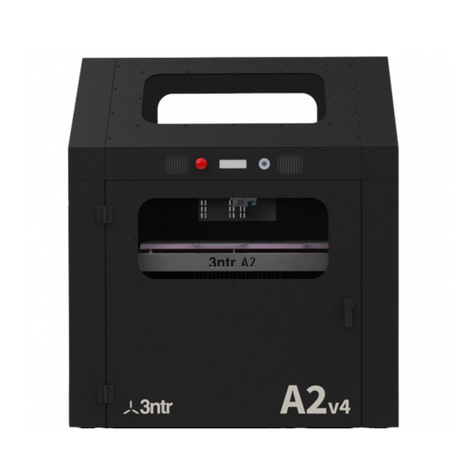
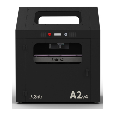
TRAK 3ntr Series User manual

TRAK®3ntr 3D Printers
Maintenance Manual V1.18
Covers Current Models:
•3ntr A2
•3ntr A4
2615 Homestead Place
Rancho Dominguez, CA 90220-5610 USA
T | 310.608.4422 |F | 310.764.2668
Service Department: 800.367.3165
Document: P/N 32237
Version: 112019

Copyright ©2019, Southwestern Industries, Inc. All rights are reserved. No part of this publication may
be reproduced, stored in a retrieval system, or transmitted, in any form or by any means, mechanical,
photocopying, recording or otherwise, without the prior written permission of Southwestern Industries,
Inc.
While every effort has been made to include all the information required for the purposes of this guide,
Southwestern Industries, Inc. assumes no responsibility for inaccuracies or omission and accepts no
liability for damages resulting from the use of the information contained in this guide.
All brand names and products are trademarks or registered trademarks of their respective holders.
Southwestern Industries, Inc.
2615 Homestead Place
Rancho Dominguez, CA 90220
Phone 310-608-4422 Fax 310-764-2668
Service Department
Phone 800-367-3165 Fax 310-886-8029

i
TRAK Machine Tools
Southwestern Industries, Inc.
TRAK 3ntr 3D Printers –Maintenance Manual V1.18
Table of Contents
1Introduction ...............................................................1
2Safety..........................................................................2
2.1 Safety Precautions ................................................................................ 2
3Main Diagnostic Checklist...........................................4
4Repair Procedures ......................................................6
4.1 No Power Diagnostic Flowchart ........................................................... 6
4.2 No Power Check .................................................................................... 7
4.3 Fuse is blown repeatedly .................................................................... 12
4.4 Mother Board Cabling ......................................................................... 12
4.5 Cooling Circuit –Maintenance Flow Chart ......................................... 20
4.6 Cooling Circuit –Drain System ........................................................... 21
4.7 Cooling Circuit –Fix Bent Piping ........................................................ 25
4.8 Cooling Circuit - Cleaning ................................................................... 28
4.9 Cooling Circuit –Pump Cleaning ........................................................ 31
4.10 Pulleys................................................................................................. 34
4.11 Heat Exchanger Cleaning.................................................................... 36
4.12 Stepper Heat Sinks –Cleaning ........................................................... 37
4.13 Belt Tension ........................................................................................ 38
4.14 Heated Chamber Diagnostic Flowchart .............................................. 39
4.15 Heated Chamber Inspect & Repair ..................................................... 40
4.16 Screw Terminals - Tighten.................................................................. 44
4.17 DC Fans –Inspect ............................................................................... 46
4.18 Extruder Gain –How to Find .............................................................. 47
4.19 DC Power Supply Test......................................................................... 47
4.20 Stepper Current Setting (OLD Stepper Drivers)................................. 49
4.21 Stepper Current Settings (Silent Drivers) .......................................... 50
4.22 Stepper Driver Replacement............................................................... 51
4.23 Feed Pressure –Check/Restore to Factory Default ........................... 52

ii
TRAK Machine Tools
Southwestern Industries, Inc.
TRAK 3ntr 3D Printers –Maintenance Manual V1.18
4.24 LCD Display Malfunction –Weird Character Display.......................... 52
4.25 Z Motor Replacement.......................................................................... 53
4.26 Heated Chamber –A4 Printer Heater Replacement........................... 53
4.27 Front Panel Removal........................................................................... 55
4.28 Machine Packaging ............................................................................. 58
4.29 Extruder Plate Change ........................................................................ 62
4.30 Print Plate Repair Procedure .............................................................. 65
4.31 Very High Temperature Hardware/Firmware Modification ............... 72
4.32 Print Server Stops Working ................................................................ 75
4.33 Print Server –Lost Password.............................................................. 75
4.34
Print Server –Files Disappeared
...................................................... 75
4.35 Print Server –Files are Visible, but Won’t Print ................................. 77
4.36
Print Server –Firmware won’t flash anymore
.................................. 79
4.37 Filament Sensor Doesn’t Work/Works Intermittently ....................... 79
4.38 Printer Jams frequently –Cooling Circuit jammed ............................ 80
4.39 Print Looks Bad –Stripes.................................................................... 83
4.40 X/Y/Z Axis Won’t Move ...................................................................... 84
4.41 Z Safety Switch Installation/Calibration............................................ 85
4.42
Z Safety Switch is triggered –machine is locked
........................... 86
4.43 Appendix A –Testing for Shorts (Continuity) .................................... 86
4.44 Appendix B –How to Test Voltage ..................................................... 89
4.45 Appendix C: Changelog...................................................................... 91
5TRAK Warranty Policy...............................................92

1
TRAK Machine Tools
Southwestern Industries, Inc.
TRAK 3ntr 3D Printers –Maintenance Manual V1.18
1Introduction
This Maintenance Guide contains information to assist skilled and trained technicians in the maintenance,
troubleshooting, and repair of the TRAK 3ntr 3D printers. It is far from complete; however, directly
addresses the most commonly encountered issues that require maintenance, service, and/or
troubleshooting with the TRAK 3NTR A2/A4 3D Printers.
Scope of the Maintenance Manual:
•Diagnostic Checklists/Flowcharts
•Repair Procedures
•Maintenance Procedures
•Upgrade Procedures
Although there is a Main Diagnostic Checklist available as a starting point for printer troubleshooting, this
guide is most efficiently utilized browsing the table of contents to select the applicable Repair Procedures
section content.
CAUTION - Information contained within this manual is a reminder for trained personnel only. This
manual does NOT replace training –untrained personnel should not perform any maintenance on any
3ntr machinery even if dutifully following the procedures depicted into this document.

2
TRAK Machine Tools
Southwestern Industries, Inc.
TRAK 3ntr 3D Printers –Maintenance Manual V1.18
2Safety
The safe set-up, calibration, and operation of your TRAK 3ntr 3D printer depends on its proper use and
precautions taken by each operator. If these activities are performed incorrectly, there are risks, not
limited to, electric shock, pinch/crush, burns, inhalation of fumes/debris that can cause serious injury or
death.
NOTE –Southwestern Industries shall not be liable for damages resulting from mis-interpretation,
misuse, error, and/or omission of the information contained within this manual.
Read and follow this Maintenance Guide. Understand the printer operation and safety precautions before
setting up, calibrating, or operating the 3D printer.
•Always wear safety glasses and safety shoes.
•Always stop the printer before opening the access door and reaching into the printer.
•Always allow the printer, printer surface plate and workpiece to cool adequately before reaching
into the printer.
•Have a qualified electrician make all electrical connections and cable wiring
•Never wear gloves, rings, watches, long sleeves, neckties, jewelry, or other loose items when
operating the printer.
2.1 Safety Precautions
1) Do not operate this machine before reading and understanding all the available manuals.
2) Do not run this machine without knowing the function of every control key, button, knob, or
handle. Ask your supervisor or a qualified instructor for help when needed.
3) Protect your eyes. Wear approved safety glasses (with side shields) at all times.
4) Allow the machine to cool before reaching into it for any reason. The printer bed, printer surface
plate, printed part, extruders/nozzles, and other printer interior components can reach very high
temperatures and cause serious burns.
5) Don't get caught in moving parts. Before operating this machine remove all jewelry including
watches and rings, neckties, and any loose-fitting clothing.
6) Keep your hair away from moving parts. Wear adequate safety headgear.
7) Protect your feet. Wear safety shoes with oil-resistant, anti-skid soles, and steel toes.
8) Take off gloves before you start the machine. Gloves are easily caught in moving parts.
9) Remove all tools (wrenches, check keys, etc.) from the machine before you start. Loose items
can become dangerous flying projectiles.
10) Never operate a 3D printer after consuming alcoholic beverages, or taking strong medication, or
while using non-prescription drugs.
11) Protect your hands. Stop the printer bed movement and extruder translation mechanism:
a. Before opening the printer access door
b. Before reaching into the machine for any reason
c. Before changing parts
d. Before removing the printer bed tray, printed parts, or filament debris
e. Before you make an adjustment to the extruder, nozzles or any interior mechanism.
12) Protect your eyes and the machine as well. Don't use a compressed air hose to remove the
debris or clean the machine.
13) Stop and disconnect the machine before you perform maintenance and repair operations.

3
TRAK Machine Tools
Southwestern Industries, Inc.
TRAK 3ntr 3D Printers –Maintenance Manual V1.18
14) Keep work area well lighted. Ask for additional light if needed.
15) Do not lean on the machine while it is running.
16) Prevent slippage. Keep the work area dry and clean. Remove obstacles of any kind around the
machine.
17) Avoid getting pinched in places where the printer bed or extruder arm movement can cause a
crush or pinch injury
18) Do not operate the printer with the printer access door open or any of the windows or service
access panels removed.

4
TRAK Machine Tools
Southwestern Industries, Inc.
TRAK 3ntr 3D Printers –Maintenance Manual V1.18
3Main Diagnostic Checklist
Figure 2.1.1 Main Diagnostic Flowchart Page 1

5
TRAK Machine Tools
Southwestern Industries, Inc.
TRAK 3ntr 3D Printers –Maintenance Manual V1.18
Figure 2.1.2 Main Diagnostic Flowchart Page 2

6
TRAK Machine Tools
Southwestern Industries, Inc.
TRAK 3ntr 3D Printers –Maintenance Manual V1.18
4Repair Procedures
CAUTION - Always remove AC power cord before attempting any maintenance on heated chamber / plate or
left part (AC power area) of the machine
CAUTION - The procedures are to be performed by trained personnel. If you didn’t attend to 3ntr
training procedures STOP NOW.
4.1 No Power Diagnostic Flowchart
Figure 4.1.1 No Power Diagnostic Flowchart

7
TRAK Machine Tools
Southwestern Industries, Inc.
TRAK 3ntr 3D Printers –Maintenance Manual V1.18
4.2 No Power Check
Tools needed before undertaking this task:
Figure 4.2.1 Multimeter
Figure 4.2.2 Phillips
Screwdriver
Figure 4.2.3 Hex Keys
1) Detach AC power cord
Figure 4.2.4 Detach Power Cord
2) Check fuse on main switch.
USE MULTIMETER TO CHECK.
A good-looking fuse may be tripped anyway.
Figure 4.2.5 Checking Fuse on Main Switch
3) Check AC power cord –swap it with another one if possible
4) Test all AC screw terminals

8
TRAK Machine Tools
Southwestern Industries, Inc.
TRAK 3ntr 3D Printers –Maintenance Manual V1.18
Figure 4.2.6 Screw Terminals for Testing
5) (A2) Remove HC fan cover
Figure 4.2.7 HC Fan Cover Removed
6)
(A2) Check HC/FAN connections
7) (A2) Disconnect safety thermostat

9
TRAK Machine Tools
Southwestern Industries, Inc.
TRAK 3ntr 3D Printers –Maintenance Manual V1.18
Figure 4.2.8 Safety Thermostat
8) (A2) Using a multimeter, assure that current is passing thru safety thermostat
Figure 4.2.9 Checking Safety Thermostat Current
9) Plug in AC power cord.
WARNING machine is powered on now
CAUTION
- KEEP EVERYONE AWAY.
Only trained maintenance people can be near the machine
Figure 4.2.10 Plug In Power Cord
10) Turn on machine –IF STILL NO POWER, go on with this checklist
11) Check that EMERGENCY button is released

10
TRAK Machine Tools
Southwestern Industries, Inc.
TRAK 3ntr 3D Printers –Maintenance Manual V1.18
Figure 4.2.11 Release Emergency Button
12) Check that current is arriving on PSU AC screw terminals.
13) Check that AC tension is present on A1-A2 contactor terminals. If yes, contactor may be defective:
replace it. If not, emergency button and /or its cabling could be damaged.
Figure 4.2.12 PSU AC Screw Terminal Current Check
14) Check that there is 24Vdc output on 24v PSU. If not, turn power off. Detach all 24V PSU outputs.
Power on again. If still no 24V, replace PSU

11
TRAK Machine Tools
Southwestern Industries, Inc.
TRAK 3ntr 3D Printers –Maintenance Manual V1.18
Figure 4.2.13 Check Output Voltage on PSU
15) Check that there is 12Vdc output on 12v PSU. If not, turn power off. Detach all 12V PSU outputs.
Power on again. If still no 12V, replace PSU
Figure 4.2.14 Check PSU Output Voltage

12
TRAK Machine Tools
Southwestern Industries, Inc.
TRAK 3ntr 3D Printers –Maintenance Manual V1.18
16) Is the green LED lit on the motherboard?
Figure 4.2.15 Green LED on Motherboard
17) If LED is not lit, turn off printer. Check for shorts on Fans and heaters. If shorts are found, remove
short. If no shorts are found replace motherboard
18)
Is LCD lit?
If not check cabling/connection –replace LCD if needed.
Figure 4.2.16 LCD Lit/Printer Ready
19) Is Jogwheel is working? If not check cabling/connection - replace jogwheel if needed.
4.3 Fuse is blown repeatedly
1) Check fuse rating: on A4 must be 5A, on A2 must be 15A
2) Unplug machine, then check all screw terminals for AC voltage (SSR, PSUs, contactor)
3) Check that fuse holder is not ruined –replace it if needed (along with switch body)
4) Be sure that machine is using latest firmware (low power consumption)
5) If still having issues, be sure that AC power is within tolerance (230V or 110V +/- 5%)
4.4 Mother Board Cabling
Motherboard is the brain of the machine: any problem here will be a problem for the entire machine.
Therefore, be sure that motherboard is wired correctly, with no loose connector or any slack cable around.
1) Jumpers
Jumpers are needed to set some hardware configurations. Be sure to set jumper position as in
the following figure:

13
TRAK Machine Tools
Southwestern Industries, Inc.
TRAK 3ntr 3D Printers –Maintenance Manual V1.18
Figure 4.4.1 Motherboard Cabling
2) Drivers
Drivers are the interface between the motherboard and the stepper motors that move XYZ and E
axes. Care must be taken to seat them without bending pins and with the correct orientation
(trimmer at right) To check current on each driver: put multimeter probes as shown below (black
probe on “-” PWR screw, red probe on selected driver trimmer).

14
TRAK Machine Tools
Southwestern Industries, Inc.
TRAK 3ntr 3D Printers –Maintenance Manual V1.18
Figure 4.4.2 Drivers
3) Northand Southconnections.
24Vdc connectors are on the lower part of the motherboard.
Fan/HC output and HB/HC temperature sensors are on the upper edge of the motherboard.

15
TRAK Machine Tools
Southwestern Industries, Inc.
TRAK 3ntr 3D Printers –Maintenance Manual V1.18
Figure 4.4.3 North/South Connectors
4) Thermocouples / servo / filament sensor / LCD / Jogwheel.
Thermocouples (E1 / E2 / E3) are used to precisely sense the temperature into the extruders. Servo
connector is plugged top right (red position for A4, green position for A2). Filament sensor is
plugged at the Black/yellow pins aside the servo connector (right for A4, left for A2).
CAUTION - BE ABSOLUTELYSURE NOTTOPLUG filament jumper onthe lower pins (red dot near
servo connector). Jogwheel connector goes (notch UP) on the ENC connector.
LCD goes (notch DOWN) on LCD connector. LCD contrast is set with the trimmer near the LCD
socket.

16
TRAK Machine Tools
Southwestern Industries, Inc.
TRAK 3ntr 3D Printers –Maintenance Manual V1.18
Figure 4.4.4 Thermocouple, servo, encoder, lcd, filament sensor
Other manuals for 3ntr Series
7
This manual suits for next models
2
Table of contents
Other TRAK 3D Printer manuals

TRAK
TRAK Airwolf EVO-T Programming manual

TRAK
TRAK 3ntr Series User manual

TRAK
TRAK 3ntr Series Programming manual

TRAK
TRAK 3ntr Series User manual

TRAK
TRAK 3ntr Series Manual

TRAK
TRAK 3ntr A2 Programming manual

TRAK
TRAK Airwolf 3D EVO-T Operating instructions

TRAK
TRAK 3ntr Series User manual

TRAK
TRAK 3ntr Series User manual

TRAK
TRAK 3ntr Series User manual