BobsCNC RP9 User manual

RP9 Assembly Instructions

2
Specifications...................................................................................................................... 3
Getting Started.................................................................................................................... 3
Safety first....................................................................................................................... 3
Required tools..................................................................................................................... 3
Building the Printer............................................................................................................. 4
Extruder Assembly.......................................................................................................... 4
Y Sub-assembly.............................................................................................................. 7
X-Subassembly............................................................................................................. 13
Frame assembly ............................................................................................................ 14
Z Assembly................................................................................................................... 15
Z - Rod Assembly........................................................................................................ 16
X Assembly................................................................................................................... 18
Extruder (cold end) Assembly...................................................................................... 20
Adding the Electronics...................................................................................................... 22
Controller Assembly..................................................................................................... 22
Motion Stepper motors ................................................................................................. 23
Limit Switches.............................................................................................................. 25
Adding The String Drive .................................................................................................. 26
Tying the knots (Uni-knot) ........................................................................................... 27
X string Drive ............................................................................................................... 27
Y String Drive............................................................................................................... 29
Adding the Extruder...................................................................................................... 31
Build Platform Assembly.................................................................................................. 33
Connecting the Controller................................................................................................. 34
Ramps1.4 Connections ................................................................................................. 34
_Toc403068513
Filament Spool Holder...................................................................................................... 36
Initial Controller Setup ..................................................................................................... 37
Arduino 2560 Firmware settings .................................................................................. 37
Power supply................................................................................................................. 38
First print (quick guide)................................................................................................ 39
Appendix........................................................................................................................... 42
Warranty and Return Policy.......................................................................................... 42
Parts included in the basic kit ....................................................................................... 42
Added parts included in the deluxe kit ......................................................................... 44

3
Specifications
5 ply Baltic birch frame
Oil hardened drill rod linear rails
Filament drive with high grip v-groove threaded coupler drives
Remote extruder with 1.75 mm drive
Foot print
Width 520 mm ( including spool holder)
Depth 550 mm ( with max travel)
Height 660 mm ( room for filament guide tube)
Print Area
X 200 mm
Y 200 mm
Z 200 mm
The complete printer part list can be found in the appendix.
Getting Started
Safety first
Safety is your responsibility. Always use the
proper protective equipment and "safety
sense" when building or operating a 3D
printer.
Printers have high voltage power supply, and extruder operating temperatures can be over
200 degrees Celsius. The operator should understand the hazards before operating a
printer.
Required tools
Please browse through the instructions and get familiar with the steps before you
begin.
To put the kit together you will need:
a Phillips screwdriver for the screws
a pair of pliers to hold the nuts
a sharp knife or a pair of side cutters to trim the zip ties and string
sand paper to clean up the plywood parts and remove sharp edges.

4
Tools you may need for the electronic setup include:
soldering iron/solder
wire cutters
multimeter to correctly set up the power supply and stepper motors and general
trouble shooting.
For the printing you will want to have:
computer with a USB to program and run the printer
calipers to measure motion distance and extrusion width
calibration block STP file
Building the Printer
We recommend a large working surface for assembling the printer. The plywood
may require some minor sanding and can be painted, stained or finished for a different
look.
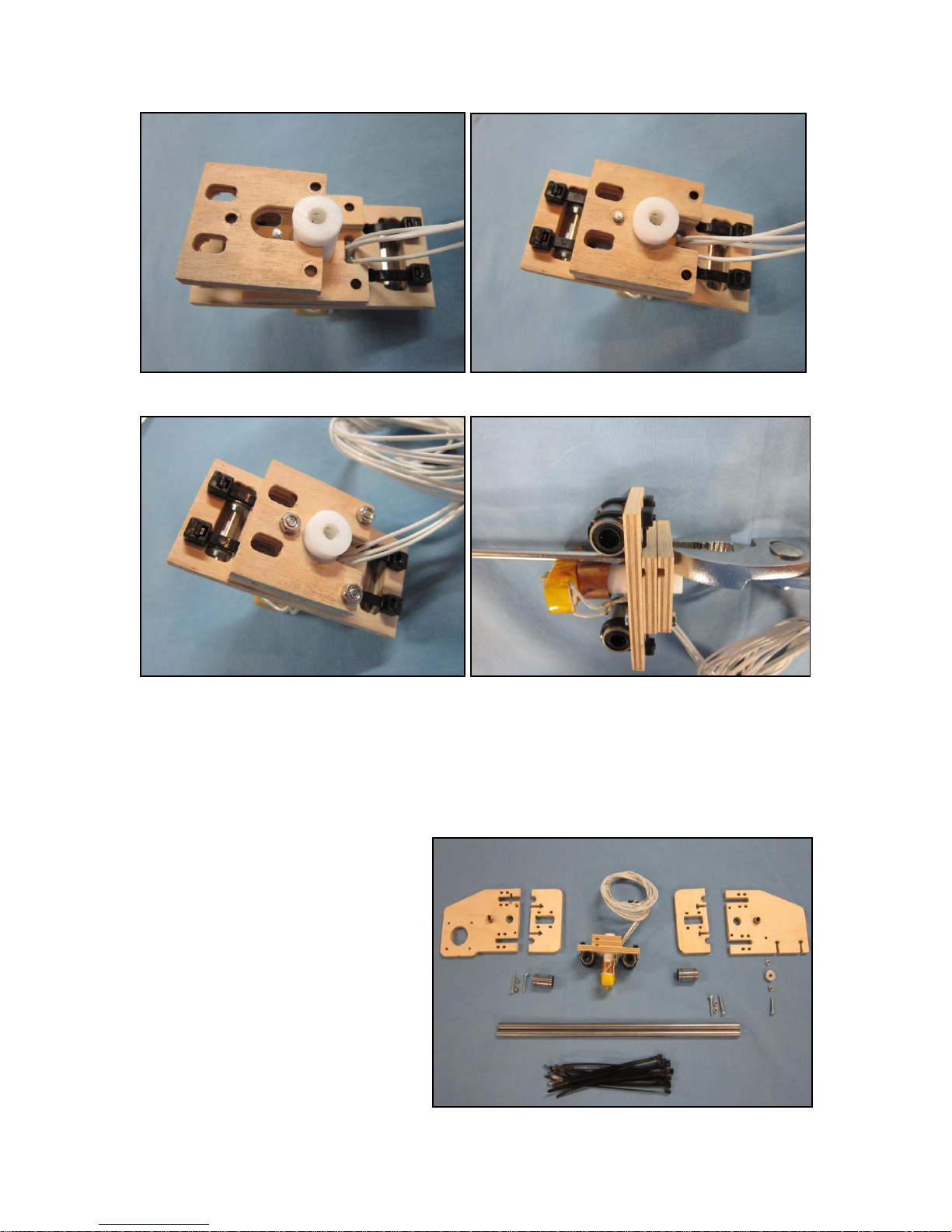
Extruder Assembly
Parts for the extruder mount assembly include:
A. 1 Extruder mount
B. 1 Extruder lock
C. 1 Extruder spacer
D. 3 M3 x 20 machine screws
E. 3 M3 nuts
F. 2 LM8UU bearings
G. 4 Large nylon ties
H. 1 Extruder
A
B
C
H

5
1. Place the bearings into the rectangular slots of the extruder mount.
2. Wrap the bearings by inserting large nylon ties through the side opposite of the bearing
into the slotted holes of the extruder mount.
3 Pull the bearing snug against the extruder mount (use pliers if needed).
4. Cut off the excess of the nylon tie.
For a clean look and string clearance, insert the nylon straps first in the inboard
holes.

6
5. Insert the 4 wires through the extruder mount from the same side as the bearings
through the wire slot.
6. Pull the wires through and re-coil them to keep them out of the way and undamaged.
7. Insert a M3 x 20 screw from the extruder side into the middle mounting hole.
8. Place the extruder through the extruder plywood mount.
9. Install the extruder spacer with the cut groove facing down..
M3 x20
7
10. Install the extruder lock to the extruder spacer with the cut groove facing down.
11. Insert the 2 remaining M3 x 20 screws into the holes.
12. Install the 3 nuts and tighten.
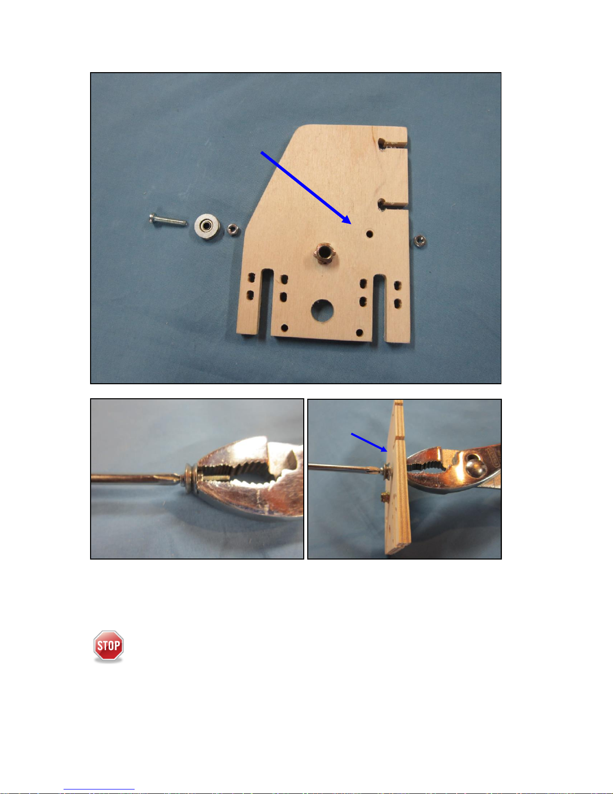
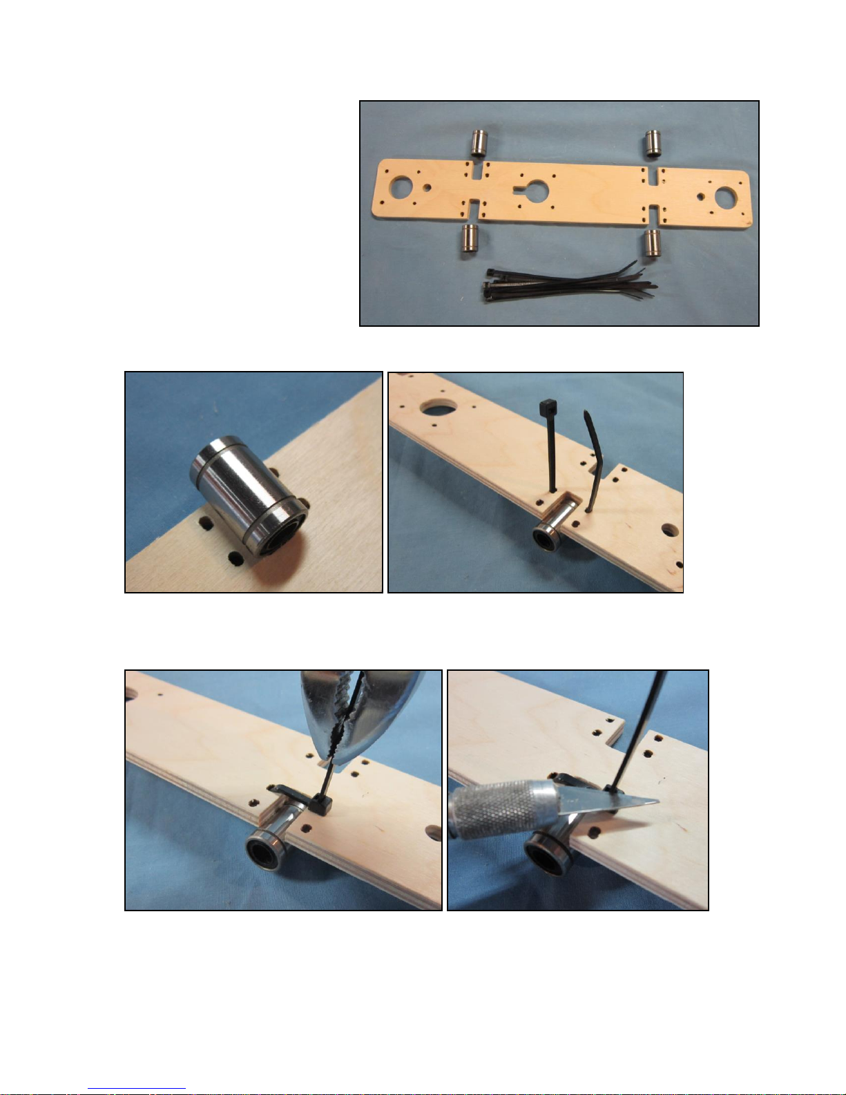
Y Sub-assembly
Parts for the Y sub-assembly include:
A. 1 Left mount
B. 2 Bearing holders
C. 1 Extruder assembly
D. 1 M3 x 16 machine screw
E. 1 Right mount
F. 4 M3 x 20 machine screws
G. 6 M3 nuts
H. V groove bearing 623VV
I. 2 LM8UU bearings
J. 12 Large nylon ties
K. 2 8mm rods
A
B
B
E
H

8
1. Place the bearings in the rectangular slots of the plywood bearing holders.
2. Wrap the bearings by inserting large nylon ties through the side opposite of the bearing
into the slotted holes of the bearing holders.
3 Pull the bearing snug against the bearing holders (use pliers if needed).
4.Cut off the excess of the nylon tie.
9
5. Insert the bearing and then the nut on the M3 x 16 machine screw.
6. Tighten the nut
7. Install the screw and bearing through the top of the right mount through the bearing
mounting hole.
8. Install and tighten the nut.
The bearing should rotate freely once installed.
Bearing mounting hole
TOP
TOP
10
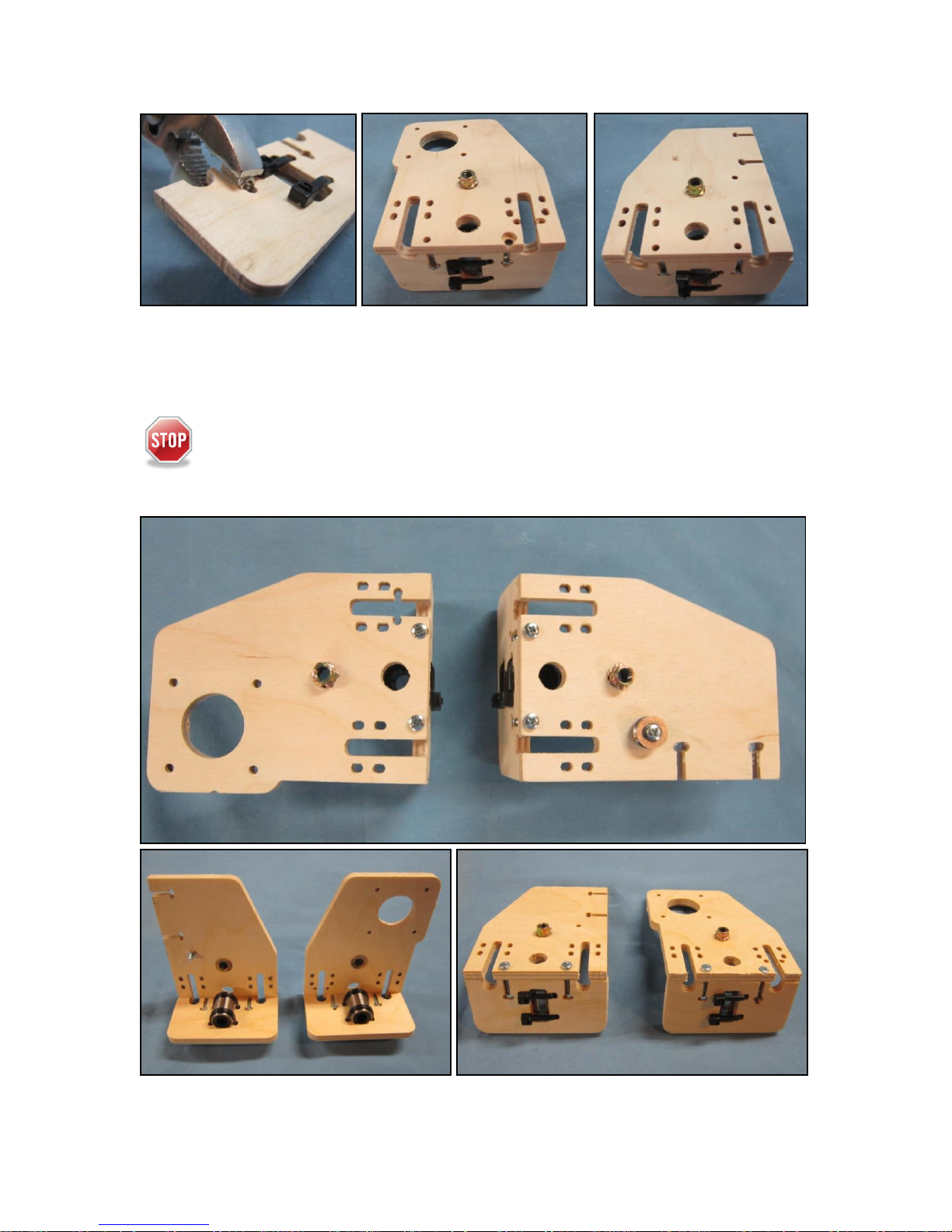
9. Press in the 4 M3 nut into the slots on the bearing holders.
10. Assemble the left and right mounts to the bearing holders with 2 M3 x20 machine
screw.
11. tighten the screws.
Note orientation is important. The bearing center should line up with the hole on
the left and right mounts.
11
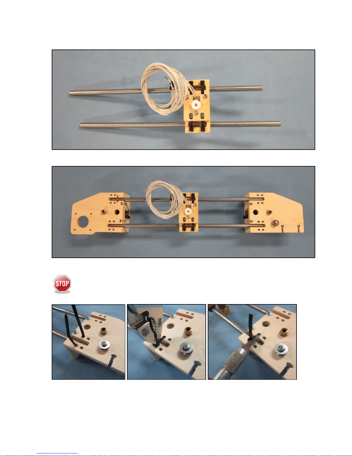
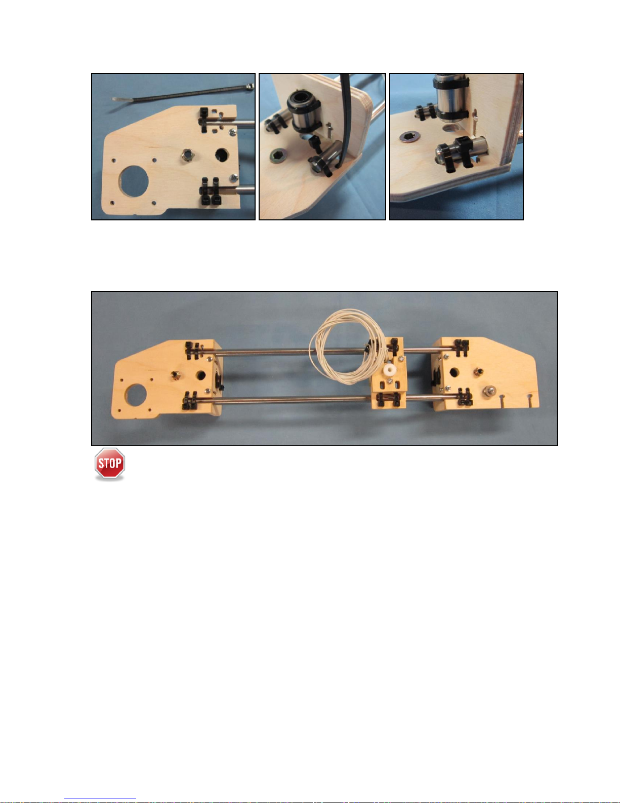
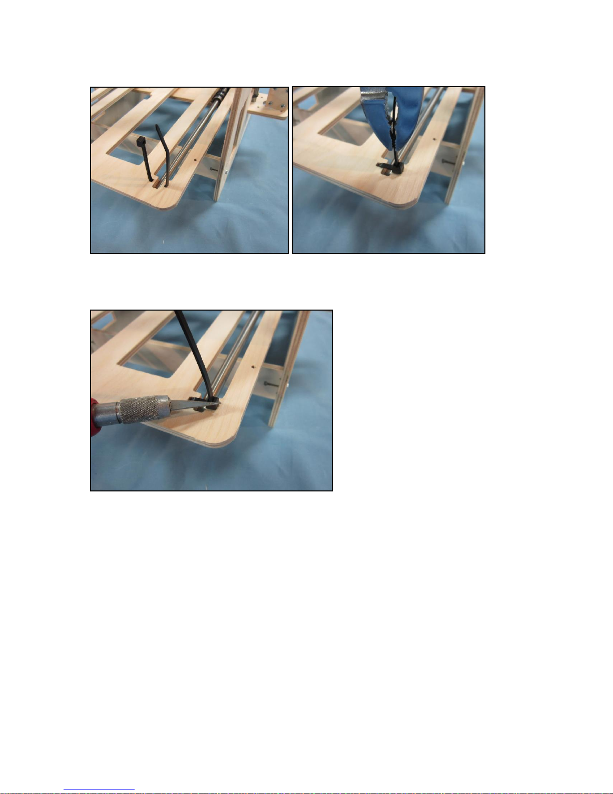
12. Slide both 8mm rods through the bearings on the extruder assembly.
13. Slide both rods into the left and right assemblies with the extruder nozzle facing
down.
Note that the nylon tie under the Y limit switch slots will be installed differently.
14. For 7 of the nylon ties, wrap the rods by inserting large nylon ties through the side
opposite of the rods into the slotted holes of the left and right mounts.
15. Pull the rods snug against the left and right mounts (use pliers if needed).
16.Cut off the excess of the nylon tie.
12
17. Wrap the rod by inserting the last large nylon tie through the same side as the rod into
the remaining slotted holes of the left mount.
18. Pull the rod snug against the left mount (use pliers if needed).
19. Cut off the excess of the nylon tie.
The extruder assembly should slide on the 8mm rods freely.
13
X-Subassembly
Parts for the x-subassembly
include:
1 Plywood cross member
4 LM8UU bearings
8 Large nylon ties
1. Place the bearings in the u-shaped slots of the cross member.
2. Wrap the bearings by inserting large nylon ties through the side opposite of the bearing
into the slotted holes of the bearing holders.
3 Pull the bearing snug against the extruder mount (use pliers if needed).
4. Cut off the excess of the nylon tie.

14
Indicator drill
marks
A
A
B
C
E
D
E
Frame assembly
Parts for the frame assembly include:
A. 2 Top braces
B. 1 Left frame
C. 1 Right frame
D. 1 X sub-assembly
E. 2 Bottom braces
F. 8 M3 x 20 machine screws
G. 8 M3 x 20 nuts
The orientation of three parts
is important.
Indicator marks on the frame
should be at the back facing inward.
The middle stepper mount
should be closer to the left frame
1. Properly orient and insert x sub-assembly into the left and right frame.
2 Press with pliers or tap the 8 M3 nuts into the slots ( the handle of the screw drive
works well)
3. Insert the top and bottom plywood braces into the slots.
4. Install and tighten the 8 M3 x20 machine screws.

15
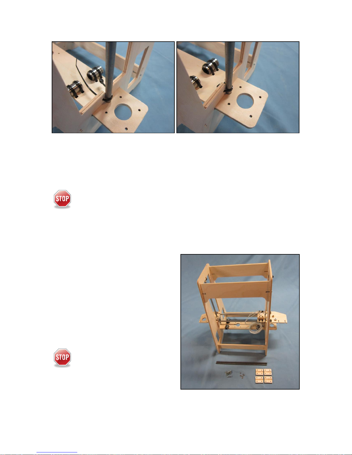
Z Assembly
Parts for the z assembly include:
1 Frame assembly
1 Y assembly
2 8mm rods
4 Large nylon ties
The orientation of top nylon ties is
important. The nylon locking block needs to be on
the outside to give maximum Y axis travel.
1. Place the Y assembly into the frame.
2. Insert the rods through the Y assembly and position them into the holes of the cross
member at the bottom and u-shaped slots at the top of the frame
2. Wrap the top of the rods by inserting large nylon ties through same side as the rod into
the slotted holes of the extruder mount.
3. Pull the rods snug against the frame (use pliers if needed).
4. Cut off the excess of the nylon ties.
16
5. Wrap the bottom of the rods by inserting large nylon ties through the side opposite as
the rod into the slotted holes of the extruder mount.
6. Pull the rods snug against the frame (use pliers if needed).
7. Cut off the excess of the nylon ties.
The Y assembly should slide on the 8mm rods freely.
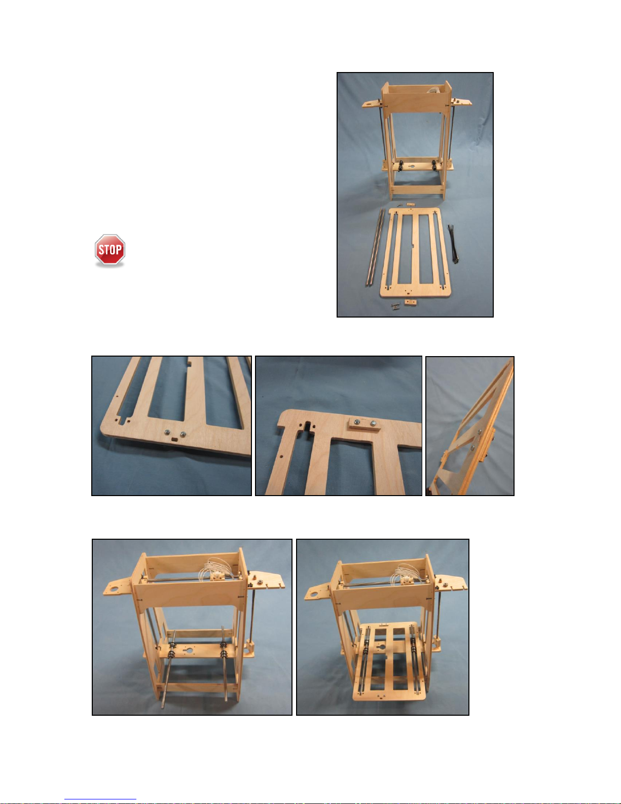
Z - Rod Assembly
Parts for the Z rod assembly include:
1 Frame assembly
2 1/4-20 threaded rods
4 Coupler halves
8 M3 x 20 machine screws
8 M3 nuts
The orientation of the coupler is
important. The larger slots are paired and
connected to the threaded rod.

17
1. Assemble each of the threaded rods into the larger coupler slots.
2. Connect the coupler halves with 4 M3 x20 screws and nuts.
3. Only snug up the screws, they will be tightened in a later step.
6. Insert both of the coupler assemblies into the threaded inserts on the Y assembly
18
X Assembly
Parts for the x assembly include:
A. 2 X string holders
B. 1 X bed mount
C. 1 Frame assembly
D. 2 8mm rods
E. 4 Large nylon ties
F. 4 M3 x16 machine screws
G. 4 M3 nuts
Note orientation. The string holder
is mounted on bottom on the front and it
is mounted on top in the rear. The cut
groove in the string holder mates with
the bed mount.
1. Install the string stops into the bed mount using 2 M3 x 16 machine screws.
2. Install the M3 nuts and tighten
2. Insert the rods into the bearings on the cross member and install the bed.
B
A
A
19
5. Wrap the bottom of the rods by inserting large nylon ties through the side opposite of
the rod into the slotted holes of the extruder mount.
6. Pull the rods snug against the frame (use pliers if needed).
7. Cut off the excess of the nylon ties.
20
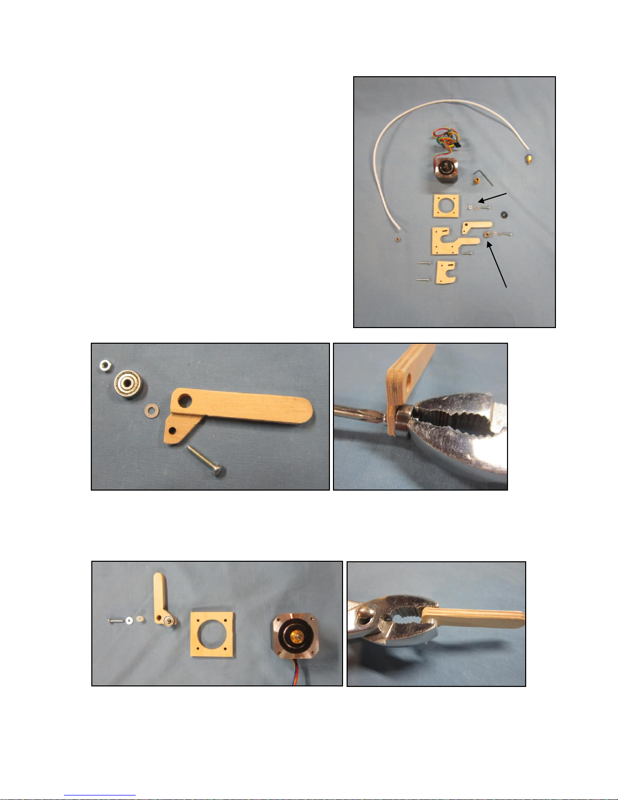
Extruder (cold end) Assembly
Parts for the cold end include:
A. 1 Backing plate
B. 1 Bearing arm
C. 1 Mid plate
D. 1 Front plate
E. 1 Drive bearing
F. 1 Nylon bushing
G. 1 Stepper motor
H. 1 Extruder drive gear
I. 1 Filament guide tube
J. 1 Filament guide tube nut
K. 1 Large washer
L. 2 M3 x16 machine screws
M. 1 Small washer
N. 1 M3 nut`
O. 2 M3 x 20 machine screws
P. 2 O-rings
1. Insert the M3 x 16 through the extruder arm.
2. Install the small washer on the screw.
3. Install the bearing on the screw.
4. Install the nut on the screw and tighten
5. Press the nylon washer into the extruder arm.
6. Insert the big washer onto the M3 x 16 machine screw.
B
D
A
E
C
F
Other manuals for RP9
1
This manual suits for next models
1
Table of contents
Other BobsCNC 3D Printer manuals


