Page 2
LED Level Confirmation and Adjustment
The output voltage of the LED supply is factory set to be between 3.5 and 4 volts. LED intensity has a direct relationship to
the video signal voltage. The acceptable range for the peak video signal voltage (of unobstructed light through the perf
hole) is between 2.7 and 5 volts (see figure 1). Under normal circumstances, the LED power supply voltage will never need
adjustment to achieve the acceptable video voltage range. However, some combinations of individual LED intensity and
projector speed may result in a video signal out side the 2.7 and 5 volt range. in that case, it may be necessary to adjust
the LED power supply.
If the top of the video waveform is not reasonably flat (+1-1 division), check for dirt, dust, or other obstruction to the light
path, and clean as necessary.
Optical Alignment
The Reader is optically aligned at manufacture and should not require adjustment unless the CCD board has been removed
or replaced (the CCD sensor is located on the CCD circuit board, Optical alignment of the sensor depends on the positron of
the circuit board). The procedure for confirming or adjusting the position of the CCD board follows.
Lateral
Lateral position can be confirmed if the video signal (of unobstructed light through the perf hole) on the oscilloscope falls in
the center of the total CCD video signal to center the video signal on the scope do the following.
1. Use the scope setup described
in the first section of these in-
structions, observebothchannel
1 and 2.
2. Run SRD film through projector.
3. The scope image should be ad-
justed to look like the diagram
at right.
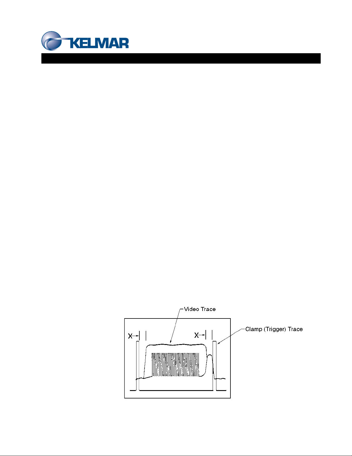
4. If theCCDcircuitboard isaligned,
the video signal of light through
the pert hole will be centered
between the falling edge of clamp (trigger trace and the rising edge of the clamp trace. As in the diagram, distance
“X’will be equal on each side of the video signal.
5. To re-align the CCD board, first loosen the lateral lock screw, and then adjust the lateral position using the lateral
adjust screw. When the video trace is centered with respect to the clamp trace, tighten the lock screw.