kenall MEDMASTER MRIPSF-480 User manual

www.kenall.com |P: 800-4-Kenall |F: 262-891-9701 |10200 55th Street Kenosha, Wisconsin 53144, USA
This product complies with the Buy American Act: manufactured in the United States with more than 50% of the component cost of US origin. It may be covered by patents
found at www.kenall.com/patents.Content of specication sheets is subject to change; please consult www.kenall.com for current product details. ©2019 Kenall Mfg.Co.
1
INSTALLATION INSTRUCTIONS
MRIPSF-480_F-7499_031919
IMPORTANT SAFEGUARDS
When using electrical equipment, basic safety precautions should always be followed, including the following:
THIS PRODUCT MUST BE INSTALLED IN ACCORDANCE WITH THE APPLICABLE INSTALLATION CODE BY A PERSON FAMILIAR WITH
THE CONSTRUCTION AND OPERATION OF THE PRODUCT AND THE HAZARDS INVOLVED. DISCONNECT POWER TO ALL CIRCUITS
BEFORE WIRING FIXTURE. INSTALL IN ACCORDANCE WITH ALL NATIONAL, STATE, AND LOCAL CODES. DO NOT CONNECT TO
AN UNGROUNDED SUPPLY. READ ALL FIXTURE MARKINGS AND LABELS TO ENSURE CORRECT INSTALLATION OF FIXTURE.
SUPPLEMENTAL INSTRUCTIONS MAY BE LOCATED ON THE FIXTURE, IN ADDITION TO THIS INSTRUCTION SHEET, REGARDING
ORIENTATION, OR MOUNTING RESTRICTIONS.
SAVE THESE INSTRUCTIONS
INSTALLATION INSTRUCTIONS
MEDMASTER™
MRIPSF SERIES
Remote Power Supply and Filter System for MRI Luminaires
This instruction sheet applies to the Kenall MRIPSF-480 Remote Power Supply & EMI Filter System. It describes the
proper mounting and wiring procedure for a typical MRI room application. A separate instruction sheet is provided
with the MRI luminaire(s). Both sheets together are intended to provide comprehensive instructions on system
installation and electrical wiring.
The remote supply & EMI lter must be installed outside the shielded MRI environment. It contains ferrous
components that can damage or interfere with MRI equipment. Complete conduit runs and wiring between
power supply, EMI lters and luminaires after all system components have been installed in their nal positions.
If luminaires are intended to be dimmed (via 0-10V dimming system), then the Kenall MRIFD-1A EMI lter (or
equivalent) must be ordered and installed.
.875 KO (9)
1.125 KO (7)
2.93
2.05 2.00 2.00
8.62
END VIEW
BACK VIEW
SIDE VIEW
.88
15.18
4.05
1.05
12.00
1.60 1.29
8.10
.31 Dia. Mounting Holes (4 places)
6.00
2.67 3.25 3.00 3.25

www.kenall.com |P: 800-4-Kenall |F: 262-891-9701 |10200 55th Street Kenosha, Wisconsin 53144, USA
This product complies with the Buy American Act: manufactured in the United States with more than 50% of the component cost of US origin. It may be covered by patents
found at www.kenall.com/patents.Content of specication sheets is subject to change; please consult www.kenall.com for current product details. ©2019 Kenall Mfg.Co.
2
INSTALLATION INSTRUCTIONS
MRIPSF-480_F-7499_031919
Power Supply Mounting Procedure
1. Locate a suitable mounting location for the AC-DC power supply/supplies. The location should be chosen based
on the following requirements:
A. Ambient Temperature/Humidity: The surrounding ambient temperature must stay below 104°C (40°C).
Allowable relative humidity is 20-90% non-condensing. Product is for DRY locations only.
B. Wire Distance: The length of 24VDC supply wires between the power supply, EMI lter and luminaires
should not exceed 50 feet (15m). This is the distance to the last luminaire within the run.
C. Ventilation: Maintain at least 3” of free-air space around all sides of the power supply enclosure.
D. Contaminants: Location should not allow excessive dirt/dust accumulation, preventing air circulation in
and around the enclosure.
2. Securely mount the enclosure to a mechanically-sound surface. Use hardware appropriate for the weight of the
enclosure and mounting surface type (not provided).
24VDC EMI Filter Mounting Procedure
1. Mount the provided 30-amp DC line EMI lter directly to outer enclosure wall via rear NPT conduit pipe using
all provided gasketing and hardware (1-5/16” diameter hole size). See Figure 1. The power supply and EMI
lter should be installed as close together as possible.
NOTE: Filter mounting surfaces must be clean, free of paint and have suitable conductive nish for maximum
grounding, shielding and provide isolation between input and termination connections.
2. Run grounded ½” conduit, with proper size conduit ttings, between the power supply and the input of the
EMI lter. Make sure all gaps, regardless of size, are closed or wrapped in copper foil tape.
Figure 1: Filter Mounting Detail

www.kenall.com |P: 800-4-Kenall |F: 262-891-9701 |10200 55th Street Kenosha, Wisconsin 53144, USA
This product complies with the Buy American Act: manufactured in the United States with more than 50% of the component cost of US origin. It may be covered by patents
found at www.kenall.com/patents.Content of specication sheets is subject to change; please consult www.kenall.com for current product details. ©2019 Kenall Mfg.Co.
3
INSTALLATION INSTRUCTIONS
MRIPSF-480_F-7499_031919
0-10V Dimming Filter Mounting Procedure
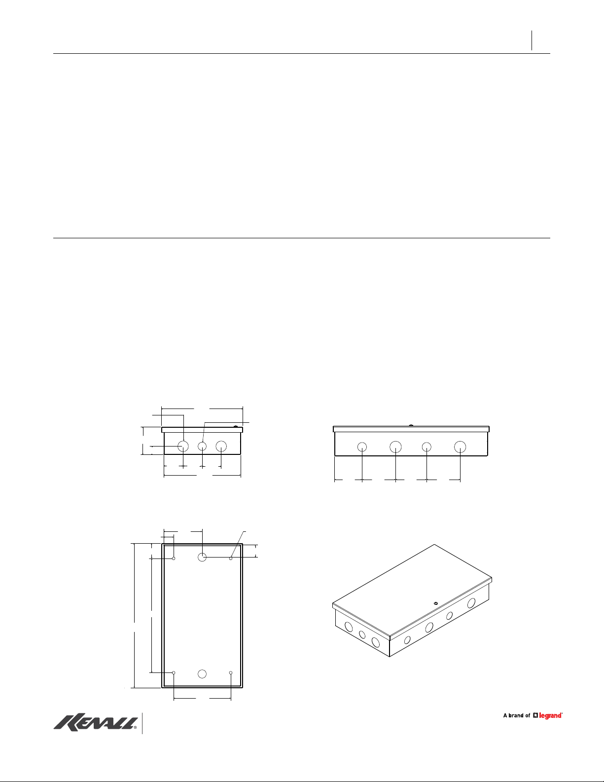
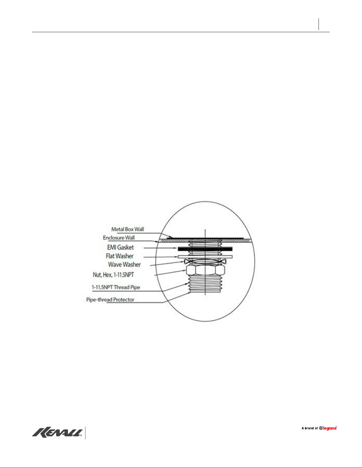
1. Mount the Kenall MRIFD-1A dimming-line lter directly to outer enclosure wall via rear NPT conduit pipe using
all provided gasketing and hardware (1-5/16” diameter hole size). See Figure 1 for details.
2. Run grounded ½” conduit, with proper size conduit ttings, between the dimmer/controller and the input of
the EMI lter. Make sure all gaps, regardless of size, are closed or wrapped in copper foil tape.
NOTE: The 0-10V dimmer must be installed outside the shielded MRI environment.
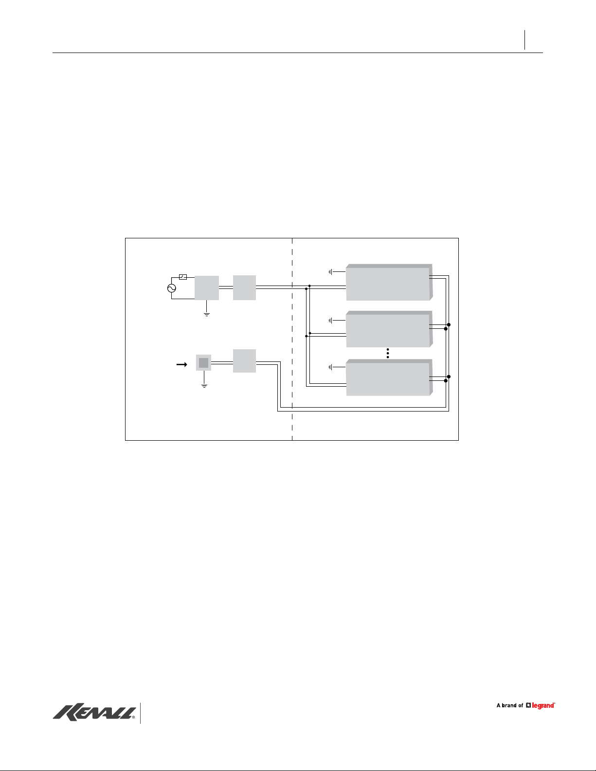
Wiring Procedure - Single Power Supply DC Filter
Use the following procedure if only one power supply and DC EMI lter are to be connected in this installation.
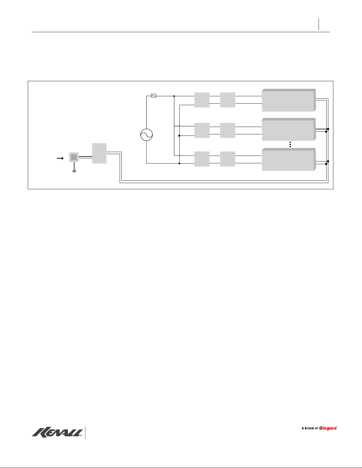
Refer to “Wiring Procedure - Multiple Power Supply/DC Filters” for multiple power supply installations. The overall
system schematic is shown within Figure 2.
1. Make 120-277VAC, 50/60Hz supply connections on the line voltage side of the power supply. Make sure a
proper ground is connected.
2. Run DC wiring, sized for the 20A maximum supply rating (supplied by others) from the power supply to the DC
EMI lter through the grounded conduit installed in “24VDC EMI Filter Mounting Procedure”.
WARNING: To prevent electrical shock, manually discharge the internal lter capacitors by
temporarily connecting eld terminals to ground (wearing insulated gloves is recommended).
3. Remove lose hardware supplied on lter eld terminal screws and install power cables to each terminal through
a crimped or solder-type ring connector (not supplied) using the supplied hardware. See Figure 3.
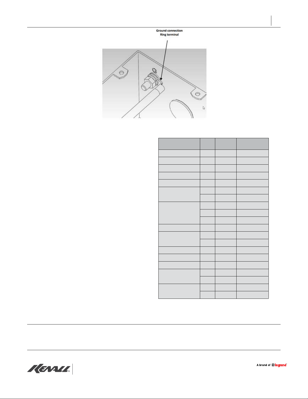
4. Remove lose hardware supplied on the ground screw terminal marked with the Green label and install a
ground wire identical in size and insulation rating to the grounded and ungrounded circuit supplied conductor,
except it shall be colored Green or Green-Yellow. Use a crimped or solder-type ring connector (not supplied, see
Figure 3). The ground wire shall be installed as part of the circuit that supplies the lter.
Luminaire 1
Luminaire 2
Luminaire N
(last)
EMI
Filter
EMI
Filter
RED
RED
BLACK
BLACK
VIOLET
GRAY
BLACK
RED
Repeat
Wiring As
Needed
INSIDE MRI ROOMOUTSIDE MRI ROOM
+
–
NOTE: ALL WIRES INSIDE MRI ROOM TO BE
INSIDE GROUNDED RIDGID ALUMINUM CONDUIT
0-10V Dimmer
(by others)
COMMON
HOT MRIPSF-480
MRIFD-1A
(or equal)
120-277VAC
50/60 Hz
AC
IN
+
24V
–
Figure 2: Single-Supply System Schematic

www.kenall.com |P: 800-4-Kenall |F: 262-891-9701 |10200 55th Street Kenosha, Wisconsin 53144, USA
This product complies with the Buy American Act: manufactured in the United States with more than 50% of the component cost of US origin. It may be covered by patents
found at www.kenall.com/patents.Content of specication sheets is subject to change; please consult www.kenall.com for current product details. ©2019 Kenall Mfg.Co.
4
INSTALLATION INSTRUCTIONS
MRIPSF-480_F-7499_031919
NOTE: Pressure terminal or pressure splicing connectors and solder lugs shall be the same or suitable materials as
the conductors.
5. Fasten eld and ground terminal hardware to a recommended torque of 18 lb-in.
6. Run DC wiring, equal in size and temperature rating to the lter input wiring, between the lter output cables
and the rst luminaire within the shielded room. All wiring must be within completely-enclosed, grounded
conduit suitable for an MRI environment. Any gaps, regardless of size, must be closed or wrapped in copper foil
tape. Special attention should be paid to the wiring entry point into the shielded space. Class 1 wiring methods
are required.
7. Make subsequent wiring connections to luminaires following any additional procedures described within the
luminaire installation instructions.
NOTE: See the “Maximum Fixture Connection” section (page 6) for the maximum number of luminaires that can be
connected to each power supply. Multiple Kenall MRI product types may be powered from a single power supply/
lter if the maximum current rating (20A) is not exceeded.
8. If 0-10V dimming is to be connected, please complete installation at this time. Refer to “Wiring Procedure –
Dimming Line“ for wiring procedure.
9. Complete any remaining steps on luminaire installation.
10. Connect power on line voltage side and test system operation. Test operation of lighting system, including
dimming functionality, during MRI machine idle mode and during scanning operations.
11. Fill out the Installation Registration Form (attached) and fax to Kenall at (262) 891-9701.
Figure 3: Ring Terminal Connections within EMI Filter

www.kenall.com |P: 800-4-Kenall |F: 262-891-9701 |10200 55th Street Kenosha, Wisconsin 53144, USA
This product complies with the Buy American Act: manufactured in the United States with more than 50% of the component cost of US origin. It may be covered by patents
found at www.kenall.com/patents.Content of specication sheets is subject to change; please consult www.kenall.com for current product details. ©2019 Kenall Mfg.Co.
5
INSTALLATION INSTRUCTIONS
MRIPSF-480_F-7499_031919
Wiring Procedure – Multiple Power Supply/DC Filters
Installations involving many luminaires within a single shielded room may require multiple power supplies (and
EMI lters) to handle the load. Please see “Maximum Fixture Connection” to determine if the application requires
multiple supplies. Wiring guidelines are the same as the previous section, please see Figure 4 below.
Wiring Procedure – Dimming Line
All Kenall MRI luminaires can dim via 0-10V control. Kenall recommends the Lutron Diva (DVSTV) and Lutron Nova
T (NTSTV-DV) series to ensure the full range of dimming can be achieved.
NOTE: In the situation where the luminaire groups are controlled by separate dimming circuits, it is imperative that
each circuit utilizes a dedicated control line lter (Kenall MRIFD-1A or equivalent).
1. Run low-voltage wiring, 18-GA minimum, from the dimmer to the control line lter through the grounded
conduit installed in “0-10V Dimming Filter Mounting Procedure”.
WARNING: To prevent electrical shock, manually discharge the internal lter capacitors by
temporarily connecting eld terminals to ground (wearing insulated gloves is recommended).
2. Solder the dimming line positive (violet) and negative (gray) conductor to solder terminal lugs L1 and L2,
respectively.
3. Remove lose hardware supplied on the ground screw terminal marked with the Green label and install a
ground wire identical in size and insulation rating to the grounded and ungrounded circuit supplied conductor,
except it shall be colored Green or Green-Yellow. Use a crimped or solder-type ring connector (not supplied, see
Figure 5).
Figure 4: Multiple-Supply System Schematic
Fixture
Group 1
Fixture
Group 2
Fixture
Group N
RED
RED
BLACK
BLACK
BLACK
RED
COMMON
HOT
120-277VAC
50/60 Hz
MRIPSF-480
AC
IN
AC
IN
AC
IN
+
24V
–
+
24V
–
+
24V
–
EMI
Filter
EMI
Filter
EMI
Filter
EMI
Filter
+
–
0-10V Dimmer
(by others)
MRIFD-1A
(or equal)

www.kenall.com |P: 800-4-Kenall |F: 262-891-9701 |10200 55th Street Kenosha, Wisconsin 53144, USA
This product complies with the Buy American Act: manufactured in the United States with more than 50% of the component cost of US origin. It may be covered by patents
found at www.kenall.com/patents.Content of specication sheets is subject to change; please consult www.kenall.com for current product details. ©2019 Kenall Mfg.Co.
6
INSTALLATION INSTRUCTIONS
MRIPSF-480_F-7499_031919
4. Fasten the ground terminal hardware to a
recommended torque of 18 lb-in.
5. Run the signal wiring, equal in specication to the
lter input wiring, between the lter output cables
and the rst luminaire within the shielded room.
Maintain polarity between input and output sides
of the lter. All wiring must be within completely-
enclosed, grounded conduit suitable for an MRI
environment. Any gaps, regardless of size, must
be closed or wrapped in copper foil tape. Special
attention should be paid to the wiring entry point
into the shielded space.
6. Make subsequent wiring connections to luminaires
following any additional procedures described
within the luminaire installation instructions.
Maximum Fixture Connection
Use the table to the right to determine the maximum
number of luminaires that can be connected to an
individual power supply. The maximum recommended
DC amperage leaving the power supply should not
exceed 20A. Multiple Kenall MRI product types may be
powered from a single power supply/lter as long as
the maximum current rating is not exceeded.
Figure 5: Signal Filter Ground Terminal
Product Lamp
Power
Amps per
Luminaire
Max. Luminaires
per Power Supply
CSMRI-22 6L 0.41 48
CSMRI-24 13L 0.76 26
CSMRI-44 26L 1.46 13
LPS5MRI-12 / LPSR5MRI-12 13L 0.76 26
ME11MRI 24L 1.46 13
MRIAUC
14L 0.76 26
27L 1.52 13
MRIDL6
13L 0.77 26
23L 1.29 15
31L 1.82 11
MRIDL4 / MRIDL4S 13L 0.77 26
MRIMAS-813
6L 0.41 48
14L 0.76 26
MRIMAS-826 19L 1.17 17
MRIMAS-838 25L 1.52 13
MRIMAS-850 32L 1.93 10
MRIT-22
23L 1.29 15
45L 2.58 7
MRIT-24
45L 2.58 7
60L 3.63 5
MRI LUMINAIRES CONNECTION PER POWER SUPPLY
For warranty information visit www.kenall.com/Resources/Certied-Performance-Warranties
For technical assistance, call 1-800-4KENALL (1-800-453-6255).
WARRANTY
CUSTOMER SERVICE
Table of contents
Other kenall Power Supply manuals