kenall Metrex Egress METEC Series User manual

Page 1of 3
Metrex Egress
METEC Series Installation Instructions
Applications
Metrex Egress METEC Series wall surface mount combination
exit sign and unit equipment for high abuse environments. See
fixture label for restrictions.
THIS PRODUCT MUST BE INSTALLED IN ACCORDANCE
WITH THE APPLICABLE INSTALLATION CODE BY A
PERSON FAMILIAR WITH THE CONSTRUCTION AND
OPERATION OF THE PRODUCT AND THE HAZARDS
INVOLVED. FOLLOW ANY SPECIFIC INSTRUCTIONS ON
LUMINAIRE LABELS.
Preparation
Read all fixture markings and labels to insure correct
installation of the fixture. Additional information may be
located on the fixture or in supplemental instructions sheets,
separate from this instruction sheet, regarding orientation,
mounting restrictions and optional equipment.
For Peace of Mind Warranty, fixture must be mounted to
building with at least 4 fasteners (4 point mounting).
Attachment to the electrical box only is NOT recommended.
WARNING: Disconnect power to the circuit before wiring
fixture.
Minimum 12” supply wire pigtails must extend from electrical
junction box for field connections within fixture enclosure.
Installation
Disassembly (Figs.1, 2): Remove SHIELD by loosening (4)
CAPTIVE SCREWS at corners. Remove INNER COVER by
disengaging snaps where shown. Loosen (2) screws retaining
REFLECTOR ASSEMBLY. Shift and remove. Remove (4) CHASSIS
SCREWS and set aside for reuse. Remove ELECTRICAL CHASSIS
assembly.
Mounting Place HOUSING over an installed electrical
junction box (drill points provided for temporary j-box
attachment prior to permanent mounting). Locate and drill 4
pilot holes in mounting surface using HOUSING as a template.
(Fig.3): For wet location installation, attach self-adhesive pad
GASKETS to HOUSING at (4) mounting holes and center wiring
hole. Using ¼” fasteners and anchors appropriate for the
mounting surface (not supplied), attach HOUSING to structure.
Figure 1
Figure 2
IMPORTANT SAFEGUARDS
When using electrical equipment, basic safety precautions should always be followed, including the following:
READ AND FOLLOW ALL SAFETY INSTRUCTIONS
Do not mount near gas or electric heaters.
Equipment should be mounted in locations and at heights where it will not be readily subject to tampering by
unauthorized personnel.
The use of accessory equipment not recommended by the manufacturer may cause an unsafe condition.
Caution: Halogen cycle lamps are used in this equipment. To avoid shattering: Do not operate lamp in excess of rated
voltage, protect lamp against abrasion and scratches and against liquids when lamp is operating, dispose of lamp
with care.
Halogen cycle lamps operate at high temperatures. Do not store or place flammable materials near lamp.
Do not use this equipment for other than intended use.
Servicing of this equipment should be performed by qualified personnel.
SAVE THESE INSTRUCTIONS

Page 2of 3
Conduit Attachment (Fig. 4) ½” trade size conduit may
be used for power entry into top, bottom or sides of HOUSING.
Locate suitable drill point and drill 7/8” dia. hole. Use proper
conduit hub and locknut for wet or damp/dry location
installation (not supplied).
Wiring (Figs. 1, 2, 5, 6): Reinstall ELECTRICAL CHASSIS
assembly using the CHASSIS SCREWS, observing proper
orientation (PC board at left), routing 12” supply wire pigtails
through opening in GEAR TRAY. Connect supply ground to
GROUND WIRE provided. Connect supply wires to appropriate
TRANSFORMER leads. Lead color coding: White= Neutral, Black=
120V, Orange= 277V, Blue= 347V. Separately cap off all unused
leads. Connect remote loads (if used) to appropriate terminal
blocks. Refer to chart for maximum allowable loads.
CAUTION: To avoid electrical overload, total
connected lamp load (factory and field installed)
should not exceed output rating.
12VDC
Emergency
4VDC Exit
Signs
2X6.5L 11W
2X12H N.A.
4X6.5L N.A.
2X6.5L 27W
2X12H 16W
2X20H N.A.
4X6.5L 14W
2X12H 24W
2X20H 8W
4X12H N.A.
2X12H 56W
2X20H 40W
4X12H 32W
4X20H N.A.
Maximum Remote
Lamp Load
Internal
Lamps
40N
24N
1
Battery
48N
80N
Figure 3
Figure 4
Figure 5

Page 3of 3
Wiring cont.
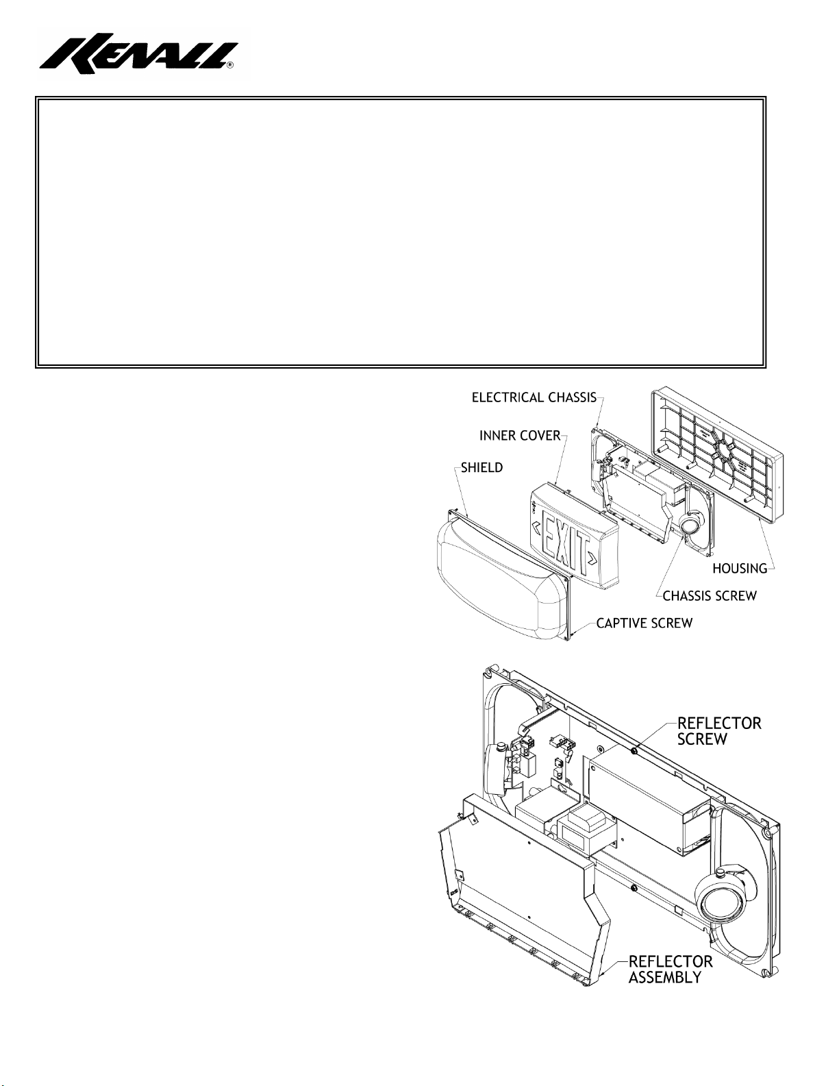
After installing ELECTRICAL CHASSIS and making field wiring
connections (AC power OFF), connect the battery to the
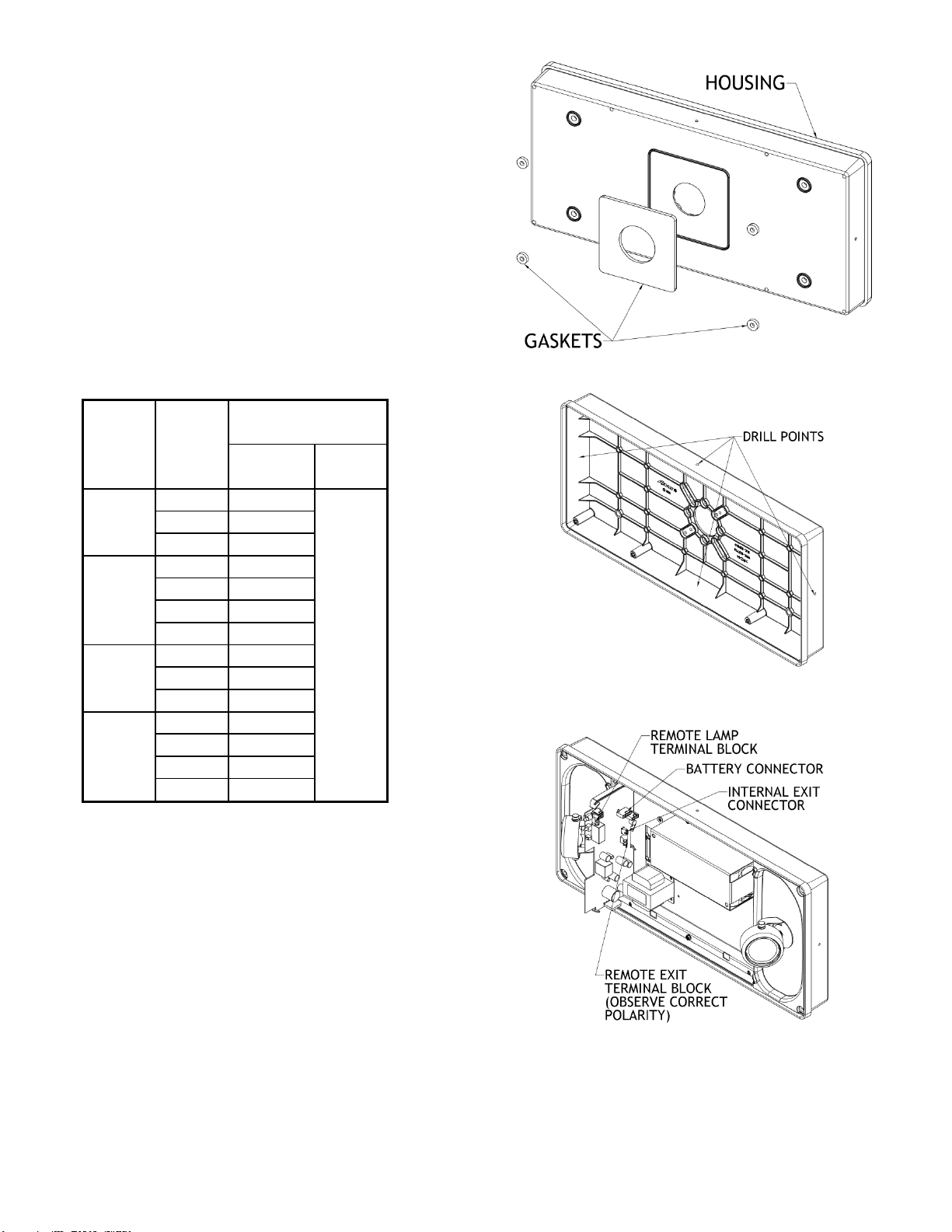
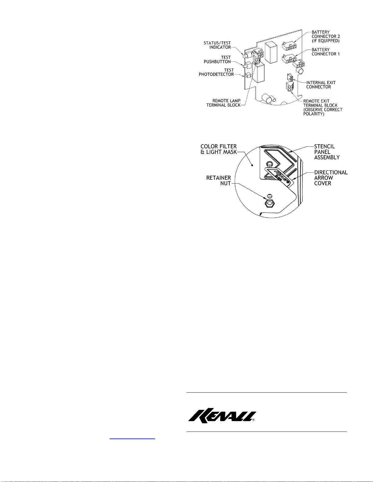
polarized 4-pin BATTERY CONNECTOR on the PC board
assembly. On units equipped with two batteries, BATTERY
CONNECTOR #1 should always be connected first and
disconnected last.
Upon connection of final BATTERY CONNECTOR, the
emergency lamps will illuminate for a few seconds and then
extinguish. This signals that the batteries are properly
connected and are protected from discharging until AC power
is established.
Connect exit sign power cable from REFLECTOR ASSEMBLY to
polarized INTERNAL EXIT CONNECTOR on PC board. Reattach
REFLECTOR ASSEMBLY to ELECTRICAL CHASSIS, observing
proper orientation (LED strip at bottom), and tighten
REFLECTOR SCREWs.
Directional Indicators (Fig. 7): Configure
DIRECTIONAL ARROWs as needed. To remove DIRECTIONAL
ARROW COVER, use 7/16” nut driver (not supplied) to loosen
RETAINER NUT approx. one complete turn. Push in cover from
outside. Tighten RETAINER NUT to secure COLOR FILTER
PANEL and aluminum LIGHT MASK (if provided). Carefully
align INNER COVER over TEST PUSHBUTTON and STATUS/TEST
INDICATOR. Snap INNER COVER to ELECTRICAL CHASSIS
assembly.
Refer to Kenall document F-2933 Metrex Egress
METEC Operation Instructions for more information.
WARRANTY
This product is warranted by Kenall to be free of
defects in workmanship and materials for a period of one year
from the date of invoice. Electrical components, including but
not limited to transformers, circuit board assemblies, LED
lamps and batteries are warranted for a period of three years
from the date of invoice. Additionally, Kenall will replace
shields, housings or mounting canopies rendered inoperable by
physical abuse any time during their product life free of
charge. A toll-free hot-line number, 1-800-331-1416 is
provided for immediate resolution of any field problems
encountered in connection with the use of Kenall’s exclusive
high abuse lighting products.
Kenall reserves the right to issue credit, repair, or
replace the defective merchandise, at its option, upon
notification and confirmation by its local representative of the
defect. Kenall also reserves the right to examine the
defective product if the defect is questionable and to deny the
warranty herein for any product altered, improperly installed,
or installed in applications for which it is not intended.
Kenall assumes no responsibility for labor or freight
costs incurred in connection with the installation, removal, or
replacement of products determined to be defective or any
other consequential or incidental damages arising from the use
of the product. Kenall’s entire liability on any claim of loss or
damage resulting from a defective product is limited to the
replacement price of the product.
The foregoing warranty is exclusive of all other
warranties and no other warranties of any kind are expressed
or implied
Kenall Manufacturing Co. www.kenall.com
4/29/09
Figure 6
Figure 7
1020 Lakeside Drive, Gurnee IL 60031 F-2932 Rev.2
1-800-4KENALL Fax: (847) 360-1781
Table of contents
Other kenall Work Light manuals
Popular Work Light manuals by other brands

Wetelux
Wetelux 92 86 59 Original instructions

Imagilights
Imagilights MOMENTS MOM-01 user manual

Havis-Shields
Havis-Shields Magnafire 5000 Specifications

Braun
Braun 64738 Owner's manual & safety instructions

Metabo HPT
Metabo HPT UB 18DD Safety instructions and instruction manual

DeWalt
DeWalt DCL023 8V Max Nstruction manual

NEXTLED
NEXTLED NT-6648 quick start guide

Sealey
Sealey TL85 instructions

PCE Health and Fitness
PCE Health and Fitness 720450 user manual

Spectroline
Spectroline NANO 365 Series quick start guide

Ledvance
Ledvance Outdoor Surface RD 13W/3000K GY IP54 quick start guide

Parkside
Parkside PAS 10 A4 Operating and safety manual