Kenet R-PRO 25 User manual
USER MANUAL
R-PRO 25 STANDING SEAM PROFILING MACHINE
Machine Serial No. .......................................

2
CONTENTS
1. GENERAL INFORMATIONS 3
1.1 BASIC SAFETY INFORMATION 3
1.2 LIABILITY 3
1.3 WARRANTY AND LIABILITY 3
2. SAFETY INSTRUCTIONS 4
2.1 SAFETY SYMBOLS AND THEIR MEANINGS 4
2.2 SUITABLE USE AND AREA OF USAGE 5
2.3 ORGANIZATIONAL PRECUATIONS 5
2.4 PROTECTIVE UNITS 6
2.5 INFORMATIVE SAFETY MEASURES 6
2.6 STAFF QUALIFICATION 6
2.7 SAFETY IN BUSINESS 7
2.8 TRANSPORTATION 8
2.8.1 SAFETY INSTRUCTIONS 8
2.8.2 DATA RELATED TO THE PRODUCT TO BE TRANSPORTED 8
3. DESCRIPTION OF THE MACHINE AND USAGE AREA 9
4. INSTRUCTIONS FOR USAGE 9
4.1 ADJUSTING ROLL / SHEET WIDTH 9
4.2 MANUFACTURING OF STANDING SEAMS 9
4.3 SIZE CORRECTIONS OF FEMALE + MALE BREAKED EDGES 9
4.4 SHEER OF THE STANDING SEAM PANEL (UP AND DOWN) 10
4.5 SHEER OF THE STANDING SEAM PANEL (SLOPING) 10
4.6 DIGITAL METER, GRIP HANDLE AND CUTTING DEVICE 10
5. MAINTENANCE 10
5.1 SAFETY MECHANISM 11
5.2 DRIVES 11
5.3 SETUP 11
6. CE CERTIFICATE 12
WARRANTY TERMS 13

3
1. GENERAL INFORMATIONS
1.1 Basic Safety Information
This user manual contains the most important information to use the machine in accordance
with safety rules.
1.2 Liability
Only the following instructions are binding and must be strictly followed.
Machine only;
●It must be used in perfect condition in terms of safety for proper use by trained specialist
personnel.
●Faults that adversely affect safety must be rectified immediately.
1.3 Warranty and Liability
Our general terms of sale and delivery apply.
Warranty and liability claims for personal injury and property damage are not possible if they are
based on one or more of the following reasons:
●Improper use of the machine
●Incorrect installation, commissioning, use and maintenance of the machine
●Operating the machine with faulty safety equipment and/or incorrectly installed or
inoperative safety and protective devices
●Ignoring the information in the operating manual regarding the transport, storage, assembly,
commissioning, operation and maintenance of the machine
●Arbitrary changes to the machine
●Arbitrary changing of the motor (eg power and speed)
●Incomplete inspection of machine parts subject to wear
●Improperly executed repairs
●Disaster situations due to external effects or force majeure
●Loading the machine or using it as a step
4
2. SAFETY INSTRUCTIONS
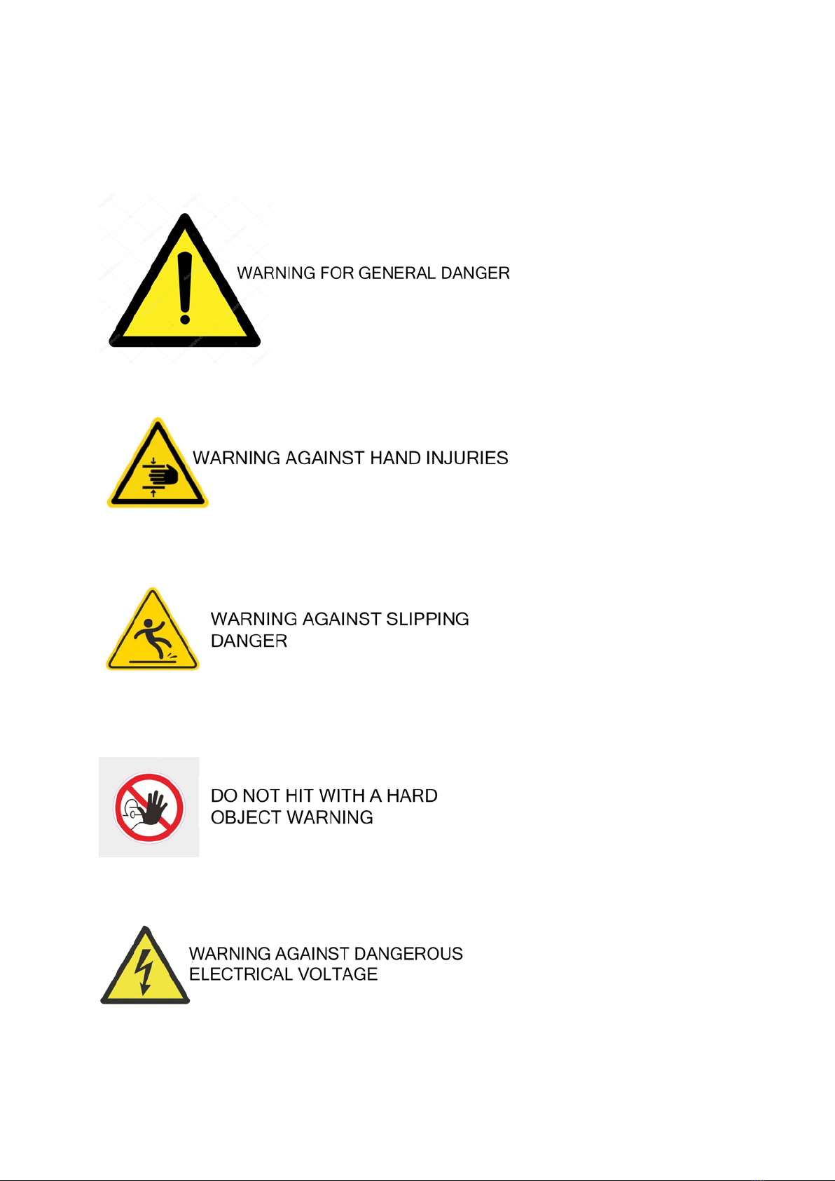
2.1 Safety Symbols and Meanings
The following definitions and signs are used for hazards in the user manual:

5
2.2 Suitable Use and Area of Usage
The system is only for forming metal coils and sheets. The defined metal dimensions should
be used within the tolerances and materials.
●Other than that, it is not suitable for any use.
●All other uses are prohibited by the manufacturer.
●The manufacturer is not responsible for any resulting damage.
●The risk lies solely with the user.
●Proper use also includes observing the operating instructions and complying with the
maintenance conditions!
2.3 Organizational Precuations
●Necessary personal protective equipment must be provided by the operator.
●All available safety devices should be checked regularly.
●Personnel assigned to use the machine must have read the user manual, especially the safety
information section, before starting to work.
●It is considered too late to do this during the study. This is especially true only occasionally,
eg. Applies to personnel working on the machine during preparation and maintenance!
●Access to the switch cabinet must always be kept open!
●The personal protective equipment prescribed by the instructions must be used!
●All safety and hazard information in the system must be observed!
●The safety and hazard information in the system must be kept fully legible!
●In case of changes in the operating behavior or in the system that are important for safety,
stop the system immediately (emergency stop button) and report the malfunction to the
authorized point / person!
●Changes, renewals or additions that may adversely affect safety should not be made without
the written consent of the supplier. This also applies to the assembly and adjustment of
safety devices and valves, as well as for welding to carrier parts.
●Spare parts must comply with the technical requirements set by the manufacturer.
●The prescribed periods for repeated checks / maintenance or specified in the operating
manual must be observed.
●A suitable workshop equipment is required to carry out maintenance measures.

6
2.4 Protective Units
Before each start-up of the machine, all protective devices must be properly fitted and
functional.
Protective devices should only be removed when:
●After stopping and disconnecting the power
●After securing the machine against restarting
When the partial components are delivered, the protective devices must be properly fitted by
the operator.
2.5 Informative Safety Measures
The user manual should be kept in the machine at all times. As a supplement to the operating
instructions, generally applicable and local regulations regarding accident prevention and
environmental protection must be available and observed.
All safety and hazard information on the machine must be kept legible and replaced if necessary.
2.6 Staff Qualification
●The system should only be used, maintained and repaired by authorized, trained and
knowledgeable personnel. These persons must have received special training on possible
hazards.
●Work on and with the system should only be carried out by trusted personnel. The legal
minimum age must be observed!
●Everyone involved in the commissioning, operation and maintenance of the system must
have read and understood the complete operating instructions, especially the safety section.
●Untrained and overly tired personnel should not work in the system.
●Only authorized personnel should work in the system!
●Personnel to be trained, trained or in general training should only work in the system under
the constant supervision of an experienced personnel!
●Work on the electrical equipment of the system should only be carried out by an electrician
in accordance with the electrotechnical rules.
●Only trained personnel should use the remote.

7
2.7 Safety in Operation
●The user is obliged to immediately notify the changes in the system that may adversely affect
the security.
●In the event of a fault, always disconnect the mains supply first.
●Doors of switch cabinets must always be closed.
●If the system continues to operate despite the activation of a safety switch, the system must
be shut down immediately. The system should only be put into operation again after the
fault has been rectified.
●Any form of work that is questionable in terms of safety is prohibited!
●Precautions must be taken to ensure that the system only works safely and in good working
order!
●The system only includes all protective and safety-related devices, e.g. The protective devices
that have been activated must be operated while the emergency shut-off devices are present
and in working order!
●The system should be checked for external damage and deficiencies at least once per shift.
Any changes (including working behavior) must be reported immediately to the competent
person / authority! If necessary, the system must be stopped and secured immediately!
●In case of malfunctions, the system must be stopped immediately and secured. The fault
must be rectified immediately!
●The maintenance area must be secured as widely as possible!
●If the system has been completely or partially shut down during maintenance and repair
work, it must be secured against unintentional restart: the main control devices must be
locked or a warning sign must be fitted to the main switch.
●The system, connections and screw connections must be cleaned with oil or cleaning agents
before starting maintenance / repair! Aggressive cleaning materials should not be used.
●Before cleaning the system with cleaning agents, all openings where cleaning agents must
not enter for safety or functional reasons must be closed. Especially the electric motor and
the switch cabinet are in danger.
●Housings/covers must be fully assembled after cleaning.
●Safe and environmentally friendly disposal of operating aids as well as replacement parts
must be ensured!

8
Work on the power supply must only be carried out by an electrician in accordance with the
technical rules.
The electrical equipment of the machine should be checked regularly. Loose connections and
melted wires should be removed immediately.
The switch cabinet must always be kept closed. Only authorized personnel are allowed
access.
Take into account that mechanical and electrical / electronic residual energies may occur in
the machine and take the relevant precautions during the training of the user personnel.
Foreseeable adjustment, maintenance and control work must be carried out in a timely
manner.
All operating materials, such as compressed air and hydraulics, must be secured against
unintentional start-up.
The machine in all maintenance, control and repair works;
●It must be de-energized and the main switch secured against unexpected restart.
●The main switch must be turned off, a warning sign must be attached against restarting.
It should be checked whether the loosened screw connections are tight. After completing the
maintenance work, it should be checked whether the safety mechanisms are working or not.
●When working with oils, greases and other chemicals, the safety regulations applicable to the
relevant product must be observed.
Oil, grease and chemicals must never reach the drain!
2.8 Transportation
2.8.1 Safety instructions
The machine should only be transported by qualified personnel.
In general, the accident prevention regulations must be observed in the transport area.
Machine entrance arms, electrical components and all components must be protected.
2.8.2 Data Related to the Product to be Transported
Measures approx: 117 cm x 133 cm x 84 cm (L x W x H)
Weight approx: 255 kg
9
3. Description of the Machine and Usage Area
Reis Roof Seam Machine is for producing clamp pans from roll or sheet from nominal size 25mm.
Compact and lightweight, it is suitable for all construction sites or workshop businesses.
All metals of the following grades and sizes can be machined:
●Maximum roll/sheet width: 700 mm
●Minimum roll/sheet width: 250 mm
●Minimum roll/sheet length: 500 mm
Considering the clamp loss of approximately 70 mm, clamps with axial dimensions between
approximately 620 mm and 180 mm can be produced.
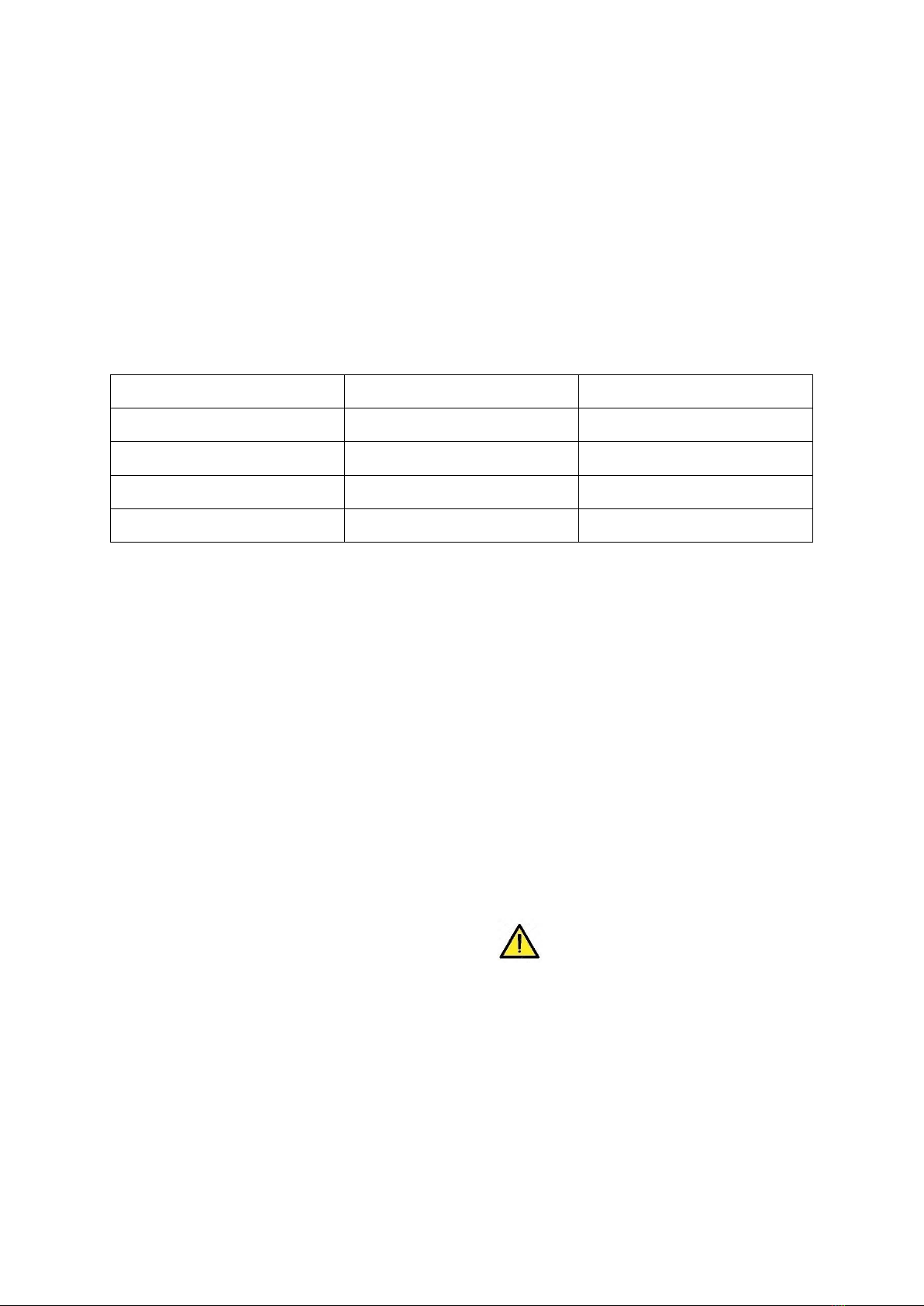
Type of Material
Tensile strength Rm(N/mm ²)
Material thickness (mm)
Painted Galvanized Sheet
≤400 N/mm²
0.50 – 0.70
Aluminum
≤400 N/mm²
0.60 – 0.80
Titanium Zinc
≤400 N/mm²
0.60 – 0.80
Copper
≤400 N/mm²
0.60 – 0.80
* MUST RECEIVE THE CONFIRMATION OF THE ABOVE MATERIAL THICKNESS AND TOLERANCE
VALUES FROM THE MATERIAL MANUFACTURER, REQUEST A WRITTEN DOCUMENT IF NEEDED.
MEASURE WITH PRECISION CALIPER AND COMPARE THE VALUES.
4. Instruction for Usage
4.1 Adjusting the width of the roll/sheet
By turning the bakelite arm located next to the machine, the roller set (in the working direction)
is moved towards the material width. The material is placed between the inlet stops and adjusted to
the gauge position. Here, care must be taken that the material is not set too tight (bouncy) or loose
(transverse movement) between the inlet limits. The metal must be easily movable between the two
entry stops.
4.2 Production of standing seams
Clamps can be produced by operating the machine with the on/off switch. During production,
care should be taken that there is enough space for the panel to take the clamp form at the exit of
the machine and that there is no one at the exit.
4.3 Size corrections of female + male breaked edges
Dimension corrections can only take place when there is no material between the input
constraints. The factory setting of the scale is zero. Zero means that the top overlay side (female ear)
= 10 mm and the bottom overlay (male ear) = 9 mm. This may vary by ± 2 mm depending on the
material.
Relevant action must be taken on the overlap side
Female ear small should be adjusted inward Female ear large should be adjusted outward
Relevant action must be taken on the underlay side
Male ear small should be adjusted inwards Male ear large should be adjusted outward

10
4.4 Sheer of the standing seam panel (Up and Down)
It can be corrected with two alignment rollers.
If the panel is pointing upwards, the alignment roller on the Overlap (female) side should be adjusted
down.
If the panel is pointing downwards The alignment roller on the lower overlap (male ear) side should
be adjusted upwards.
4.5 Sheer of the standing seam panel (Sloping)
Problem: The seam pan comes out of the machine obliquely from beginning to end. The male and
female ear are markedly different from each other at the beginning and end.
Reason: The ONLY reason for this is that the upper guide adjustment has been missed due to
tampering with the fixing screws on the intake arm.
It is inconvenient and prohibited to perform this operation by unauthorized persons. Otherwise, the
machine will be out of warranty. In order to return to the Factory Settings, the machine must be
delivered to us.
4.6 Digital Meter, Grip Handle and Cutting Device
●The machine will stop automatically when it reaches the length entered in the digital
counter.
●Pull the clutch lever towards you and the clutch mechanism is engaged.
●By pulling the scissors at the entrance, the metal is cut, after cutting the scissors are brought
back to the starting position
●After pressing the RST button on the digital counter, the machine must be restarted.
●Metal inside the machine min. After advancing 20 cm, the clutch mechanism is deactivated
by pushing the clutch arm towards the machine body. The roll coming from behind moves
towards the inside of the machine. These steps are repeated until the desired number of
clamp pans is reached.
5. Maintenance
Before any maintenance work on the machine, the power supply must be cut off and the
machine secured against restarting!
Control and adjustment processes should be carried out at the authorized service every year.
11
5.1 Safety Mechanism
Safety devices must be checked for function at all times. (enclosures, protective grilles, etc.)
Defective or damaged safety devices e.g. Switches, enclosures etc. must be repaired or replaced
immediately.
5.2 Drives
In construction site operation, lubrication must be carried out every week.
The following parts should be cleaned and re-lubricated at regular intervals.
Special dental spray should be used for teeth.
After approx. 100 operating hours, the above maintenance work must be carried out. The
lubrication condition must be checked every week during overload or difficult site operation. If
necessary, maintenance and lubrication should be done.
All gears should be checked after 1,000 – 2,000 operating hours and gear oil added if necessary.
Repeated checks of electrical equipment and functional checks of safety-related equipment
should be carried out annually.
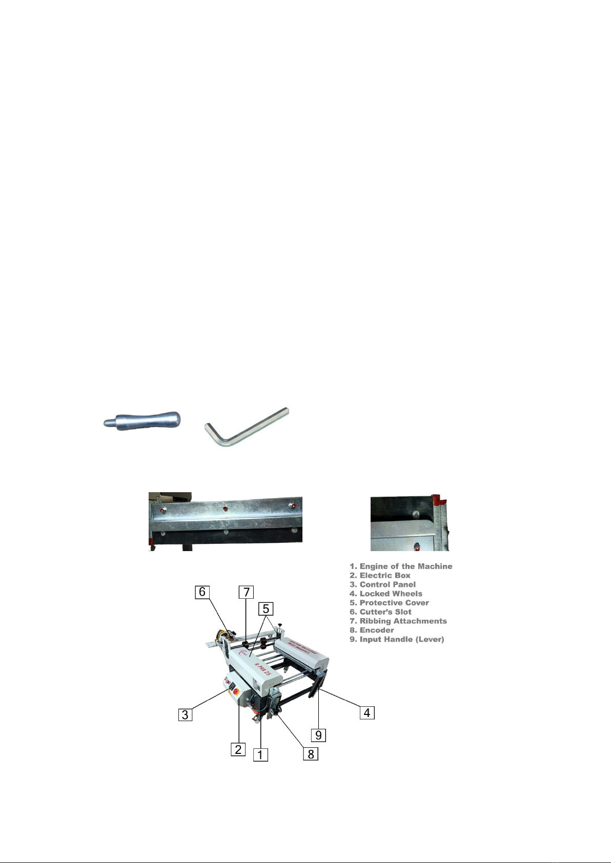
5.3 Setup
Please screw the adjusment handle to its place with
allen wrench.
Don’t change these adjusments which is colored red on the Input Handle!!!

12

13
Warranty Certificate for 12-month Warranty
Warranty Terms
1. We provide a 12-month warranty, effective from the date of purchase.
2. If you want to benefit from the warranty service, contact the authorized person and send the
machine with all its accessories in the packaging and storage box. Include a report in your
post with an understanding of the type of complaint.
3. The warranty applies only to defects caused by manufacturing or material defects. During the
warranty period, the relevant parts will be replaced or fixed free of charge according to our
decision. No other rights can be claimed. Replaced parts become our property.
4. In case of damage, transportation and packaging costs incurred for shipping and returning
the machine, as well as the costs of the called technician, belong to the buyer. No transport
risk is assumed.
5. Repair or replacement of individual parts does not extend the original warranty period for
the machine.
6. If repairs or interventions are made by persons not authorized in writing, the warranty will
be voided. The buyer has to cancel the reverse.
7. Damages caused by using or connecting the machine other than our user and maintenance
manual are not covered by the warranty.
8. In particular, the warranty does not cover:
a) Damages or defects caused by force majeure (lightning strike, storm, flood) or other
external influences.
b) From the moment the machine is shipped from the authorized dealers warehouse, the
responsibility belongs to the customer. Damages that may occur during transportation
are not covered by the warranty.
c) Damages caused by improper use or other deficiencies not based on manufacturing or
material faults.
d) Wear damage due to excessive use, premature wear of valves, seals and other parts
subject to this event due to type of use.
e) Damage to the power cord and plug
9. To take advantage of the warranty, the date of purchase must be documented with a copy of
the invoice with the machine number and date of purchase.
Table of contents


