28
5
/
16
"
Side Panel
Door Open+
21
3
/
4
"
35
5
/
8
" -
36
3
/
8
"
30"
31
5
/
16
"
Min.
cutout
width
3
/
4
"
3
/
4
"
31
1
/
2
"Formed or tiled
countertop
trimmed 3/4" back
at front corners of
countertop opening.
21
3
/
4
" min.**
22
1
/
8
" max.
CABINET
FRONT
1
1
/
8
"
22
7
/
8
" min.
††
23
1
/
4
" max.
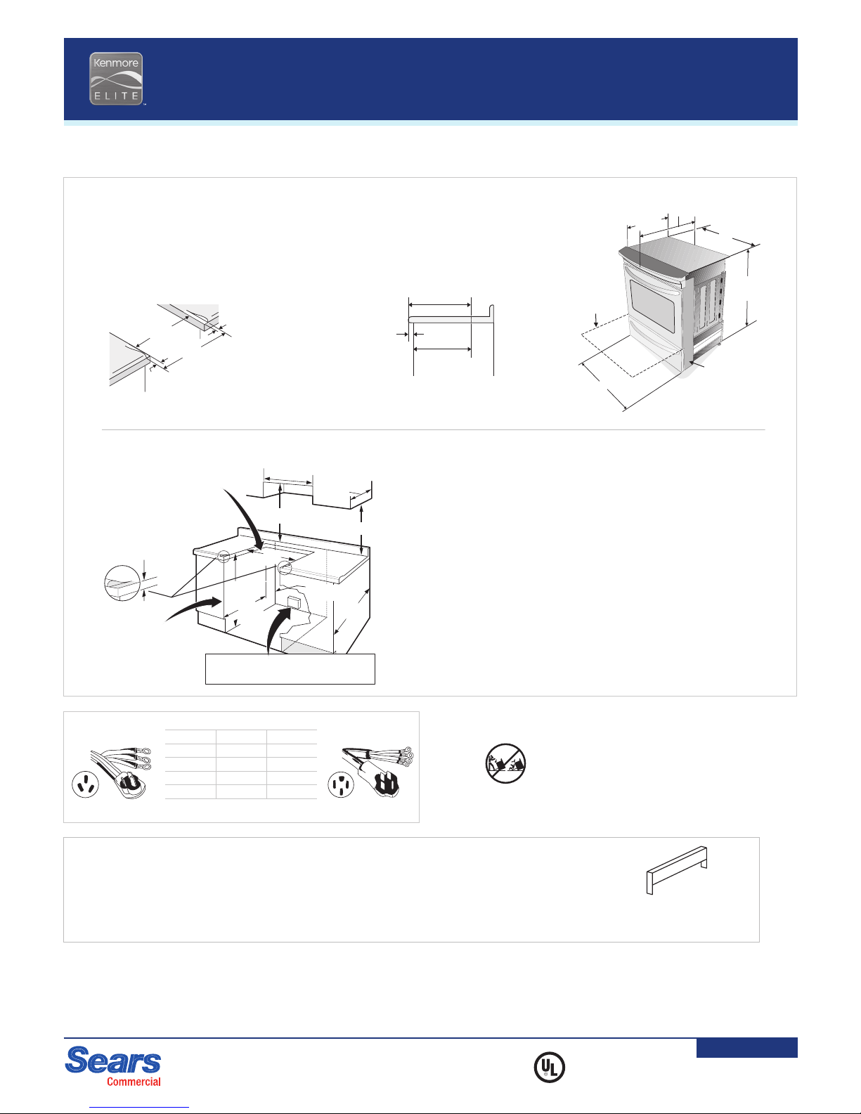
COUNTERTOP PREPARATION
The cooktop sides of the range fit over the cutout edge of your countertop. Countertop must be level.
If you have a square finish (flat) countertop, no countertop preparation is required. Cooktop sides lay directly on edge of countertop.
Formed front-edged countertops must have molded edge shaved flat 3/4" from each front corner of opening.
Tile countertops may need trim cut back 3/4" from each front corner and/or rounded edge flattened.
If the existing cutout width is greater than 30 1/16", reduce the 3/4" dimension.
Shave Raised
Edge To Clear
31
1
/
2
" Wide
Cooktop.
1
1
/
2
" Max.
13"
30" Min.
For existing 29" cutout width
opening, you must call the Sears Service
Center for optional thinner side panels.
Also you must prepare the countertop
edge as shown in “Counterdepth
Preparation”.
Locate Cabinet
Doors 1" Min. From
Cutout Opening
18" Min.
Approx. 1
7
/
8
"
30" Min.*
30"
†
±
1
/
16
"
35
5
/
8
" Min.
36
5
/
8
" Max.
24" Min.
21
3
/
4
"
Min.**
22
1
/
8
"
Max.
Grounded Junction Box or Wall Outlet Should Be
Located 8" to 17" (20.3 - 43.2 cm) From Right of Cabinet
and 2" to 4" From Floor
††For cutouts below 22 7/8", applaince will slightly show out of the cabinet.
**Note: Minimum cutout depth is increased to 24" with optional backguard.
Note: Rear Top Filler Kit ships with product
Do not pinch the power supply cord or flexible gas conduit between the range and the wall.
Do not seal the range to the side cabinets.
*Note: 24" min. clearance between the cooktop and the bottom of the cabinets when the bottom
of the wood or metal cabinet is protected by not less than 1/4" flame retardant millboard covered
with not less than No. 28 MSG sheet metal, 0.015" stainless steel, 0.024" aluminum, or 0.020"
copper. 30" min. clearance when the cabinet is unprotected.
†Note: To avoid cooktop glass breakage for cutout with more than 30 1/16", make sure appliance
is centered in the counter opening while pushing it in. Raise leveling legs at maximum position,
insert the appliance in the counter and then level. Make sure the unit is supported by the leveling
legs and not by the cooktop glass itself.
+Allow at least 19 1/4" clearance for door depth when it is open.
Shave Raised Edge
To Clear Space for
31
5
/
16
" Wide Cooktop.
1
1
/
2
" Max.
Locate
Cabinet Doors
1" Min. From
Cutout
Opening
13" Min.
18" Min.
30" Min.*
30" Min.
Right side wall
looking from front
LLAW
5" Min.
From Wall Both
Sides
For existing 29" cutout width
opening, you must call the Sears Service
Center for optional thinner side panels.
Also you must prepare the countertop
edge as shown in “Counterdepth
Preparation”.
30"
†
±
1
/
16
"
36
5
/
8
" Max.
35
5
/
8
" Min.
31
1
/
2
"
Exact App.
1
7
/
8
"
24" Min.
21
3
/
4
" Min.
22
1
/
8
" Max.
Grounded Junction Box or Wall Outlet
Should Be Loacted 8" to 17" From Right
Cabinet and 2" to 4" From Floor.
Shave Raised Edge
To Clear Space for
31
1
/
2
" Wide Cooktop.
1
1
/
2
" Max.
Locate
Cabinet Doors
1" Min. From
Cutout
Opening
13" Min.
18" Min.
30" Min.*
30" Min.
LLAW
10" Min.
From Wall Both
Sides
For existing 29" cutout width
opening, you must call the Sears Service
Center for optional thinner side panels.
Also you must prepare the countertop
edge as shown in "Counterdepth
Preparation".
30"
†
±
1
/
16
"
36
5
/
8
" Max.
35
5
/
8
" Min.
31
1
/
2
"
Exact App.
1
7
/
8
"
24" Min.
Grounded Junction Box or Wall Outlet Should Be
Located 8" to 17" From Right of Cabinet and
2" to 4" From Floor
22
1
/
8
"
Max.
21
3
/
4
"
Min.
28
5
/
16
"
Side Panel
Door Open+
21
3
/
4
"
35
5
/
8
" -
36
3
/
8
"
30"
31
5
/
16
"
Min.
cutout
width
3
/
4
"
3
/
4
"
31
1
/
2
"Formed or tiled
countertop
trimmed 3/4" back
at front corners of
countertop opening.
21
3
/
4
" min.**
22
1
/
8
" max.
CABINET
FRONT
1
1
/
8
"
22
7
/
8
" min.
††
23
1
/
4
" max.
COUNTERTOP PREPARATION
The cooktop sides of the range fit over the cutout edge of your countertop. Countertop must be level.
If you have a square finish (flat) countertop, no countertop preparation is required. Cooktop sides lay directly on edge of countertop.
Formed front-edged countertops must have molded edge shaved flat 3/4" from each front corner of opening.
Tile countertops may need trim cut back 3/4" from each front corner and/or rounded edge flattened.
If the existing cutout width is greater than 30 1/16", reduce the 3/4" dimension.
Shave Raised
Edge To Clear
31
1
/
2
" Wide
Cooktop.
1
1
/
2
" Max.
13"
30" Min.
For existing 29" cutout width
opening, you must call the Sears Service
Center for optional thinner side panels.
Also you must prepare the countertop
edge as shown in “Counterdepth
Preparation”.
Locate Cabinet
Doors 1" Min. From
Cutout Opening
18" Min.
Approx. 1
7
/
8
"
30" Min.*
30"
†
±
1
/
16
"
35
5
/
8
" Min.
36
5
/
8
" Max.
24" Min.
21
3
/
4
"
Min.**
22
1
/
8
"
Max.
Grounded Junction Box or Wall Outlet Should Be
Located 8" to 17" (20.3 - 43.2 cm) From Right of Cabinet
and 2" to 4" From Floor
††For cutouts below 22 7/8", applaince will slightly show out of the cabinet.
**Note: Minimum cutout depth is increased to 24" with optional backguard.
Note: Rear Top Filler Kit ships with product
Do not pinch the power supply cord or flexible gas conduit between the range and the wall.
Do not seal the range to the side cabinets.
*Note: 24" min. clearance between the cooktop and the bottom of the cabinets when the bottom
of the wood or metal cabinet is protected by not less than 1/4" flame retardant millboard covered
with not less than No. 28 MSG sheet metal, 0.015" stainless steel, 0.024" aluminum, or 0.020"
copper. 30" min. clearance when the cabinet is unprotected.
†Note: To avoid cooktop glass breakage for cutout with more than 30 1/16", make sure appliance
is centered in the counter opening while pushing it in. Raise leveling legs at maximum position,
insert the appliance in the counter and then level. Make sure the unit is supported by the leveling
legs and not by the cooktop glass itself.
+Allow at least 19 1/4" clearance for door depth when it is open.
Shave Raised Edge
To Clear Space for
31
5
/
16
" Wide Cooktop.
1
1
/
2
" Max.
Locate
Cabinet Doors
1" Min. From
Cutout
Opening
13" Min.
18" Min.
30" Min.*
30" Min.
Right side wall
looking from front
LLAW
5" Min.
From Wall Both
Sides
For existing 29" cutout width
opening, you must call the Sears Service
Center for optional thinner side panels.
Also you must prepare the countertop
edge as shown in “Counterdepth
Preparation”.
30"
†
±
1
/
16
"
36
5
/
8
" Max.
35
5
/
8
" Min.
31
1
/
2
"
Exact App.
1
7
/
8
"
24" Min.
21
3
/
4
" Min.
22
1
/
8
" Max.
Grounded Junction Box or Wall Outlet
Should Be Loacted 8" to 17" From Right
Cabinet and 2" to 4" From Floor.
Shave Raised Edge
To Clear Space for
31
1
/
2
" Wide Cooktop.
1
1
/
2
" Max.
Locate
Cabinet Doors
1" Min. From
Cutout
Opening
13" Min.
18" Min.
30" Min.*
30" Min.
LLAW
10" Min.
From Wall Both
Sides
For existing 29" cutout width
opening, you must call the Sears Service
Center for optional thinner side panels.
Also you must prepare the countertop
edge as shown in "Counterdepth
Preparation".
30"
†
±
1
/
16
"
36
5
/
8
" Max.
35
5
/
8
" Min.
31
1
/
2
"
Exact App.
1
7
/
8
"
24" Min.
Grounded Junction Box or Wall Outlet Should Be
Located 8" to 17" From Right of Cabinet and
2" to 4" From Floor
22
1
/
8
"
Max.
21
3
/
4
"
Min.
22-49614,
22-49616
22-49624,
22-49626
RANGE CORD REQUIRED
Order Wire Length
22-49614 3 4 ft.
22-49616 3 6 ft.
22-49624* 4 4 ft.
22-49626* 4 6 ft.
*Complies with 1/1/96 NEC code revision for new construction and remodeling
All ranges are equipped with an Anti-Tip device. The installation of this
device is an important, required step in the installation of the range.
22-4105X.PDF
22-41053/9
Page 2 of 2
Effective 04/04/11
03311
Due to Sears policy of continuous improvement on its products, Sears
reserves the right to change materials and specifications without notice.
Before installing, consult installation instructions packed with product
for current dimensional and installation data.
ACCESSORIES (OPTIONAL)
Call Sears Parts at 1-800-225-2864.
SIDE PANEL KIT
Includes two full size (right and left) panels.
NOTE: Product is shipped with 4 1/2" min.
width panels. Order this full size kit as needed.
22-628-903066-9010 – Black
BACKGUARD
22-628-903046-9010 – Black
LEVELING LEG EXTENSION KIT
22-628-903065-9010
Shave Raised
Edge To Clear
31
1
/
2
" Wide
Cooktop Rim
Dual-Fuel:
10" Min.
From Wall
Both Sides
1 1/2" Max.
Do not pinch the power supply cord or flexible gas conduit between
the range and the wall. Do not seal the range to the side cabinets.
*Note: 30" minimum clearance for dual-fuel model (24" for radiant model)
between the cooktop and the bottom of the cabinet when the bottom of the
wood or metal cabinet is protected by not less than 1/4" flame retardant
millboard covered with not less than No. 28 MSG sheet metal, 0.015"
stainless steel, 0.024" aluminum, or 0.020" copper. 36" minimum clearance
for dual-fuel model (30" for radiant model) when the cabinet is unprotected.
**Note: Minimum cutout depth is increased to 24" with optional backguard.
Locate
Cabinet Doors
1" Min. From
Cutout
Opening
Grounded Junction Box or
Wall Outlet Should Be Located
8" to 17" From Right Cabinet
and 2" to 4" From Floor
13" Min.
18" Min.
30" Min.*
30" Min.
30"
36" Std.
35 3/8"
Min.
21 3/4" min.**
22 1/8" max.
24" Min.
NOTE: 19
1
/
4
" min. clearance
for door depth when it is open
31 1/2"
Min.
cutout
width
3/4"
3/4"
31 1/2"
COUNTERTOP PREPARATION
The cooktop sides of the range fit over the cutout
edge of your countertop. Countertop must be level.
If you have a square finish (flat) countertop, no
countertop preparation is required.
Formed front-edged countertops must have
molded edge shaved flat 3/4" from each front corner
of opening.
Tile countertops may need trim cut back 3/4" from
each front corner and/or rounded edge flattened.
If the countertop opening width is greater than the
minimum cutout width, adjust the 3/4" dimension.
CABINET
FRONT
1 1/8"
22 7/8" min.†
23 1/4" max.
21 3/4"
min.**
22 1/8"
max.
†For cutouts below 22
7
/
8
"
, appliance
will protrude slightly from cabinets
WALL
21 3/4"
28 5/16"
1 5/16"
Formed or tiled
countertop
trimmed 3/4" back
at front corners of
countertop opening.
35 3/8" -
36 3/8"
30"
Regulator
(Dual-fuel only)


