jurop RV360 User manual

I
IN
NS
ST
TA
AL
LL
LA
AT
TI
IO
ON
N,
,U
US
SE
EA
AN
ND
D
M
MA
AI
IN
NT
TE
EN
NA
AN
NC
CE
EM
MA
AN
NU
UA
AL
L
EN RV360 - RV520
Rev.
11
20-10-2021
O
OR
RI
IG
GI
IN
NA
AL
LI
IN
NS
ST
TR
RU
UC
CT
TI
IO
ON
NS
S

INSTALLATION
,
USE AND MAINTENANCE MANUAL
–
RV360-520
REV
.
11
20-10-2021
2 / 32
Jurop SpA
Via Crosera n° 50
33082 Azzano Decimo, PN (Italia)
T
EL
.
+
39
0
4
34
6368
11
F
AX
.
+39
0
434
6
36812
http://www.jurop.it
e-mail: [email protected]
20
21
–
Jurop
–
Azzano Decimo (PN
)
Reproduction, electronic storage and dissemination, even partial, are prohibited.
Jurop reserves the right to modify the products described in this manual without prior notice.
Any product names mentioned herein are the trademarks of their respective owners.

INSTALLATION
,
USE AND MAINTENANCE MANUAL
–
RV360 - 520
REV
.
1
1
20-10-2021
3 / 32
Jurop SpA
Via Crosera n° 50
33082 Azzano Decimo, PN (Italia)
T
EL
.
+39
0
434
636811
F
AX
.
+39
0
434
636812
http://www.jurop.it
e-mail: [email protected]
Contents
1. General warnings pag. 4
1.1 Introduction 4
1.2 Spare part request 4
1.3 Warranty terms and conditions 4
2. Technical data pag. 5
2.1 Dimensions and arrangement 5
2.2 Performances 7
2.3 Sound pressure level 7
2.4 Usage Limitations 7
2.5 Lubrication 8
3. Safety and accident prevention pag. 8
3.1 General recommendations 8
3.2 Intended use 8
3.3 Conveyed fluids 8
4. Installation pag. 9
4.1 Checking upon receipt 9
4.2 Storing in the warehouse 9
4.3 Handling and installation 9
4.4 Mounting 9
4.5 Vacuum – pressure line 10
4.6 Inverter actuator 10
4.7 Pump mounting - Drive connection 11
5. Start up pag. 13
5.1 Starting-up of the pump 13
5.2 Precautions of use 13
6. Maintenance pag. 14
6.1 Ordinary maintenance 14
6.2 Extraordinary maintenance 15
7. Malfunctions: troubleshooting pag. 19
8. Scrapping pag. 19
9. Accessories pag. 20
SPARE PART DATA SHEET –RV 360 21
SPARE PART DATA SHEET –RV 520 23
SPARE PART DATA SHEET –RV HYD 25
SPARE PART DATA SHEET –ACCESSORIES 26
10.
Cooling fans installation
instructions
pag. 29

INSTALLATION
,
USE AND MAINTENANCE MANUAL
–
RV360-520
REV
.
11
20-10-2021
4 / 32
Jurop SpA
Via Crosera n° 50
33082 Azzano Decimo, PN (Italia)
T
EL
.
+
39
0
4
34
6368
11
F
AX
.
+39
0
434
6
36812
http://www.jurop.it
e-mail: [email protected]
1.1. Introduction
• This booklet contains the necessary instructions for a correct
installation, running, use and maintenance of the pump, as well as
some practical suggestions for a safe operating.
• The knowledge of the following pages will grant a long and
trouble-free operation of the pump.
• Following the instructions below contributes to limiting pump repair
expenses by extending its duration, as well as preventing hazardous
situations, thereby increasing its reliability.
• If the pump is driven by an hydraulic motor please refer to
manufacturer's specific manual.
• It is recommended to:
Understand and apply carefully the instructions before
running the pump.
Keep the booklet at hand and have it known to all operators.
• Below is a brief description of the symbols used in this manual.
If these safety rules are not respected, operators can
be injured and the pump or oilers damaged
remarkably.
If these safety rules are not respected, the pump or
system can be damaged.
Suggestions for an environment friendly use of the
pump.
Suggestions for an environment friendly use of the
pump.
• The graphic representations and photographs contained in this
manual are there to illustrate the product in the parts that make it up
and in specific operating phases. Though the model shown in the
manual may differ from the one purchased, the operating principle at
the base of the illustrated operating phase is the same.
• Pump has to be fitted with its own tag reporting the following data:
Model, Serial number, Year, Max speed, Max pressure.
Pic. 1.1
1.2. Spare part request
• Use only genuine spare parts for maintenance and repairs. To
order spare parts, provide the following details:
EXAMPLE:
a) The model of the pump (see pump tag): RV 520
b) The serial number of the pump (see pump tag): K90001
c) A description of the parts (see parts list): VANE
d) The quantity (see parts list): N°5 PZ
e) The code number of the part (see parts list): 16016 069 00
1.3. Warranty terms and conditions
• Compliance with the installation, use and maintenance instructions
provided by this manual is crucial for the recognition of warranty
against defective parts.
1. General warnings

INSTALLATION
,
USE AND MAINTENANCE MANUAL
–
RV360 - 520
REV
.
1
1
20-10-2021
5 / 32
Jurop SpA
Via Crosera n° 50
33082 Azzano Decimo, PN (Italia)
T
EL
.
+39
0
434
636811
F
AX
.
+39
0
434
636812
http://www.jurop.it
e-mail: [email protected]
• The RV models are rotary vacuum pumps cooled by high efficiency contrapposed fans. The airflow reduces the temperature of the internal
parts normally subjected to wear like bearings, vanes and sealings.
• The RV models are suitable for heavy-duty operation. The pumps are equipped with an automatic lubrication system and a positive
displacement pump. The oil tank is side-mounted. The oil piping are made in copper.
• A pneumatic or hydraulic version of the built-in 4-way vacuum/pressure manifold is available on request.
• The non-return valve is integrated in the pump manifold.
• There are two tangential vanes inspection ports, on the pump housing.
• The RV models are available in flanged version (FL).
• Drive system:
Direct with smooth shaft;
With hydraulic motor.
2.1. Dimensions and arrangement
[mm] A B C D E F G H I L M N O P
RV 360 830 442,5 581,5 294 220 404 154 23,5 416 25 109 Ø69 192 384
RV 520 975 438,5 605 334 286 477 162 15,5 429 29,5 95 Ø 84 210 392
2. Technical data
CCW ROTATION CW ROTATION
FLANGE VERSION (FL)

INSTALLATION
,
USE AND MAINTENANCE MANUAL
–
RV360-520
REV
.
11
20-10-2021
6 / 32
Jurop SpA
Via Crosera n° 50
33082 Azzano Decimo, PN (Italia)
T
EL
.
+
39
0
4
34
6368
11
F
AX
.
+39
0
434
6
36812
http://www.jurop.it
e-mail: [email protected]
RV with hydraulic transmission
[mm] A B C D E F G H I L M N O in O out
RV 360 HYD 1111 442,5 581,5 529 220 685,5 154 156 416 25 109
Ø
69 G 1”¼ G 1”½
RV 520 HYD 1239 438,5 605 527 286 741 162 149 429 29,5 95 Ø 84 G 3/4 G 1”
RV with accessories
[mm] A B C D E F G H I L
RV 360 830 460,5 675 511 416 253 181 192 488 384
RV 520 975 463,5 696,5 477 429 279 175 210 486 392
ØRV 360 RV 520
ADJUSTABLE
CONVEYOR
76 •
80 •
100 •
FIXED CONVEYOR
76 •
80 • •
100 •
FLANGE VERSION (FL)

INSTALLATION
,
USE AND MAINTENANCE MANUAL
–
RV360 - 520
REV
.
1
1
20-10-2021
7 / 32
Jurop SpA
Via Crosera n° 50
33082 Azzano Decimo, PN (Italia)
T
EL
.
+39
0
434
636811
F
AX
.
+39
0
434
636812
http://www.jurop.it
e-mail: [email protected]
2.2. Performances
Performances RV 360 RV 520
Air flow under free air condition l/min 10200 14700
m³/h 612 882
Air flow 60% vacuum rate l/min 9400 12915
m³/h 564 775
Max. vacuum at continuous duty % 80 80
Max. vacuum % 95 95
Power required at free port kW 14 kW 19
Power required at max. vacuum kW 11 kW 16
Airflow at 0.5 relative bar (1.5 abs.) kW 18 24
Airflow at 1.0 relative bar (2.0 abs.) kW 22 30
Max. relative pressure bar (bar abs) 1 (2) 1 (2)
Sound pressure level Lp(A) - Pump with exhaust silencer; distance: 7m in open field vuoto 60% dB(A) 74 76
Oil consumption g/h 140 160
Oil tank capacity l 4 4
Weight
RV…D kg 175 234
RV…D (FL) kg 166 210
RV…HYD kg 205 250
RV…HYD (FL) kg 196 240
REFERENCE CONDITIONS
Conveyed gas: air Vacuum condition: atmospheric discharge. Absolute reference pressure: 1013mbar
Ambient reference temperature: 20°C Vacuum functioning: free outlet Pressure condition: atmospheric suction.
Vacuum pump operating at max. speed Actual performance may vary of +/- 5%.
Flow / Power
Model Free ports Vacuum rate Abs. pressure
20% 40% 60% 70% 80% 90% 1,5 bar 1,8 bar 2,0 bar
RV 360
m3/h 612 605 595 564 453 310 106 570 550 540
l/min 10200 10080 9913 9400 7550 5166 1766 9496 9163 8997
kW 14 13,5 13 12,6 12,3 11,9 11,2 18 20,5 22
RV 520
m3/h 882 860 840 775 670 480 150 780 740 712
l/min 14700 14330 14000 12915 11165 8000 2500 13165 12330 11865
kW 19 18,2 17,7 16,9 16,4 16,2 16,1 24 27,5 30
Data at nominal speed Actual performance may vary of +/- 5%.
2.3. Sound pressure level
Lw (A)
Noise power of the only pump, without drive transmission suction group, mufflers. [dB(A)]
RPM VACUUM /PRESSURE RV 360 RV 520
NOMINAL SPEED vac 80% 89 91
Δ press 0,6 bar 100 102
2.4. Usage limitations
Modello Max. Speed – Operating speed (RPM) P2(bar ABS) T2(°C) T2- T1(°C) Room
Temperature
Minimum Ordinary Max
RV 360 800 rpm 1100 rpm 1300 rpm 2,0 bar 180°C 150°C -20 / +40°C
RV 520 800 rpm 1100 rpm 1300 rpm 2,0 bar 180°C 150°C -20 / +40°C
P1: absolute pressure during suction P2: absolute pressure during delivery T1: temperature during suction T2: temperature during delivery

INSTALLATION
,
USE AND MAINTENANCE MANUAL
–
RV360-520
REV
.
11
20-10-2021
8 / 32
Jurop SpA
Via Crosera n° 50
33082 Azzano Decimo, PN (Italia)
T
EL
.
+
39
0
4
34
6368
11
F
AX
.
+39
0
434
6
36812
http://www.jurop.it
e-mail: [email protected]
2.5. Lubrication
Recommended oils: Mineral oil anti-wear
Room T° Viscosity ENI ESSO SHELL TOTAL MOBIL BP TEXACO Q8
Under 10°C ISO VG 46 Acer 46 Nuto 46 Morlina S2 B 46 Drosera MS 46 Nuto H 46 Bartran HV 46 Rando HD 46 Shubert 46
Over 10°C ISO VG 150 Acer 150 Nuto 150 Morlina S2 B 150 Drosera MS 150 Nuto H 150 Bartran HV 150 Rando HD 150 Shubert 150
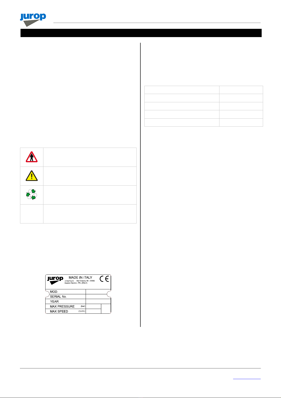
Attention:
Carefully apply these prescriptions.
3.1. General recommendations
• When transporting the compressor use proper slinging. Store the
compressor in stable places.
• Installation and maintenance must be carried out with the unit
totally disengaged from its drive system and must be performed by
qualified personnel.
• Use adequate clothing (avoid ties, loose sleeves, necklaces and
so on) and suitable protection equipment (gloves, protection glasses,
boots...).
• Before each maintenance operation, stop the pump and restore
the atmospheric pressure.
• Make sure that all the parts of the unit are idle and cool, before
performing any maintenance operation.
• To prevent errors and hazardous situations, establish what each
operator is responsible for in the different maintenance operations.
• Do not start the machine if the protection devices provided for
transmissions are removed. Replace damaged part.
• Final manufacturer must make the transmission inaccessible by
means of a fixed guard or interlocked movable guard.
• Operators working nearby must avoid prolonged exposure to the
noise emitted by the aspirator, if not equipped with the proper ear-
protection devices (IPDs recommended: ear protectors).
• When the pump is running, some parts may reach very high
temperatures (above 70°C). Use all necessary precautions to avoid
contact.
• Avoid accidental suction of solids: solids may be projected at high
speed through the exhaust manifold and cause injures. A filter must be
mounted on the suction line (Mesh 55).
• Pressure relief valve: point the air flux away from the operators.
• Do not use the aspirator over its designed limits: the machine may
be damage and the operator may be injured.
Do not exceed the speed and the power supply
parameters indicated in the technical tables (see
par 2.2 – 2.4).
• Based on the final use of the decompressor, the insertion in the
housing machine and the typology of the same, the designer of the
housing machine must apply safety signals (pictograms) to warn the
operator on the risk still present. These pictograms essentially refer to
three categories:
Signals prescribing the use of Individual Protection Devices (IPDs)
such as, in this case, the use of gloves and ear protectors.
Signals indicating to pay particular attention to the dangers related
to the machine’s components, such as: risk of dragging in the
transmission equipment and contact with hot surfaces.
Signals indicating specific parts of the machine for an easier
identification, such as: greasing points, oil tanks, etc.
3.2. Intended use
• The vacuum pumps RV are designed to convey filtered air into
systems for the vacuum production (example: systems for the suction
of powders or liquid wastes). Any other usage shall be considered
improper.
• Do not sack toxic substances and inflammable or explosive
gasses, since the internal components of the pump may reach high
temperatures.
Avoid suction of toxic (poisonous) explosive or
flammable gasses because internal components
may reach high temperatures.
• Avoid suction of liquids or solids; they can seriously damage the
pump.
Attention: liquids or solids infiltrations can
seriously damage the pump.
• Do not run the pump over its designed operating limits (see par.
2.5): it may break and transmission can be damaged.
3.3. Conveyed fluids
• RV are suitable for conveying filtered air. Before conveying other
kind of gases, verify compatibility with pump’s characteristics.
• The machine was not designed and built to operate in
environments with potentially explosive atmosphere (outdoor or
indoor).
• Please contact JUROP’s Technical dept. if necessary.
3. Safety and accident prevention

INSTALLATION
,
USE AND MAINTENANCE MANUAL
–
RV360 - 520
REV
.
1
1
20-10-2021
9 / 32
Jurop SpA
Via Crosera n° 50
33082 Azzano Decimo, PN (Italia)
T
EL
.
+39
0
434
636811
F
AX
.
+39
0
434
636812
http://www.jurop.it
e-mail: [email protected]
Pic. 4.1
1. Manifold
2. Non return valve
3. Girante raffreddamento
4. Air cooling conveyors
5. Fan protection
6. Oil Tank
7. Oil level
8. Oil filler cap
9. Lubrication pump
10. Vane inspection ports
11. Fixed / turning conveyor (upon request)
12. Suction filter kit (upon request)
4.1. Checking upon receipt
• When the goods are delivered, make sure that all parts in perfect
condition and have suffered no damage during shipping.
• Make sure the vacuum pump has its identification plate affixed on
the front cover. Pumps without such identification are to be considered
anonymous and potentially dangerous: in such an event, they must not
be used, otherwise the manufacturer will be deemed free from any
liability whatsoever.
4.2. Storing in the warehouse
• If the pump will not be installed inside a short time after delivery:
Remove the guards from the ports and spray a film of protective oil
over the inner surfaces of the body, rotors and sides. Then attach
again the guards;
Store in a closed and dry place. Renew the preserving oil
periodically.
• To temporarily store a used pump, follow the instructions below:
Thoroughly clean the pump.
Equip the pump with suitable anti-corrosion protection.
4.3. Movimentazione e installazione
• Before each movement, verify that the lifting equipment has a
suitable capacity (check the weight of the decompressor, possibly
showed in this manual, in the paragraph 2.2).
• Do not lift the packaging or the machine when moving more than
50 cm from the ground. Proceed with the final lifting only near the
installation point.
• Harness the machine with suitable straps / chains near the main
body, paying attention to the position of the mass centre of gravity to
ensure the load stability.
Warning: do not stand under the machine when it
is lifted during the installation.
4.4. Mounting
• The mounted aspirator must be accessible for maintenance and
firmly fixed on a frame or angled base with a 3° max inclination on X
and Y axes (see Fig. 4.1). The structure must be fit to avoid flexions or
vibrations.
• Provide enough space for air ventilation and disposal of heat when
pump is running. See Fig. 4.2 and 4.3 for indication of the distance to
be respected.
Pic. 4.2
Pic. 4.3
4. Installation

INSTALLATION
,
USE AND MAINTENANCE MANUAL
–
RV360-520
REV
.
11
20-10-2021
10 / 32
Jurop SpA
Via Crosera n° 50
33082 Azzano Decimo, PN (Italia)
T
EL
.
+
39
0
4
34
6368
11
F
AX
.
+39
0
434
6
36812
http://www.jurop.it
e-mail: [email protected]
• Provide the necessary space to reach all points of lubrication
control (oil level), and the oil tank filler cap, the lever of the 4-way
switch, vanes inspection ports.
• The oil tank is mounted on the suction side of the housing. Thus,
the rotary direction determines the pump overall dimensions. See also
paragraph 2.1.
• In case of RV with hydraulic motor, provide the necessary space
to disassemble the motor itself and proceed with joint lubrication.
Pic. 4.4
• In the event that the decompressor is electrically isolated, connect
it to the ground or make it equipotential with the housing machine.
Check that the paint does not prevent its passage.
4.5. Vacuum - pressure line
• See figure 4.5.
• In order to avoid the suction of liquids, a primary flow shutoff valve
(Pos. 1) and a secondary shutoff (Pos. 2) are to be mounted on the
suction line. If necessary, also apply a suction filter (Pos. 3) to prevent
solids from entering.
• The silencer (Pos. 4) applied to the pump exhaust - besides
reducing the noise level - is designed to separate the oil mist expelled
from the pump outlet port. The separator must be easily drained from
oil and condensate accumulated at regular intervals.
• The diameter of the vacuum or pressure line pipes must be
properly dimensioned to the pump flow and, in any case, it must be
larger than the diameter of the ports.
• The pipes weight or their dilatations must not solicit the pump
housing. Use high temperature resistant rubber connections.
• Before mounting, remove the port protections. All pipes and line
components must be clean.
• Avoid restrictions and tight curves as much as possible, if not
strictly necessary.
• Exhaust pipe can reach high temperatures. Hence, they must be
properly isolated.
• An over-pressure safety relief valve (Pos. 5) should be mounted in
order to prevent the overloading of the vacuum pump. Mount the valve
near the pump without applying any gate valves on the line.
• A vacuum relief valve (Pos. 6) should be applied to limit the
maximum vacuum rate at 80% in order to prevent the pump running at
continuous duty from overheating.
• Venting shutter (Pos. 9): it is also useful to cool down the
overheated pumps as well as for their internal wash-up. Direct the air
flow away from the operators.
• Thermostat (Pos. 8): it must be installed at maximum 150 mm from
the exhaust port. The sensitive element must reach the pipe centre.
Safety thermostat on manifold is supplied on request.
Pic. 4.5
1Primary shutoff 6Vacuum relief valve
2Secondary shutoff 7Manometer -1 / +3 bar
3Suction filter 8Thermostat
4Silencer – oil separator 9Venting shutter
5Overpressure safety valve
4.6. Vacuum-pressure inverter: remote control
actuators
• A specific design of the vacuum-pressure diverter available on
request enables the application of a pneumatic or hydraulic angular
actuator (90°).
• See the exploded view at the end of the manual for spare parts.
Pneumatic actuator Hydraulic actuator
Fluid Filtered, dried compressed
air Hydraulic oil ISO-L-HM
Filtration ISO 8573-1 classe 4
(15 micron) ISO 4406 21/19/16
Temperature °C -20 ÷ +80 -20 ÷ +80
Rated pressure bar 5.6 150
Maximum pressure bar 8.4 200
Supply holes G 1/4 G 1/8
7
1
3
2
6
5
4
8
9

INSTALLATION
,
USE AND MAINTENANCE MANUAL
–
RV360 - 520
REV
.
1
1
20-10-2021
11 / 32
Jurop SpA
Via Crosera n° 50
33082 Azzano Decimo, PN (Italia)
T
EL
.
+39
0
434
636811
F
AX
.
+39
0
434
636812
http://www.jurop.it
e-mail: [email protected]
Hydraulic actuator installation
• Adjust movement speed using the two built-in valves.
• Use a closed-centre distributor or apply a block valve.
Pneumatic actuator installation
• Adjust movement speed by applying two unidirectional flow control
valves.
For both actuators
• Adjust speed: full rotation should not take less than 1 second.
• Fluid filtration: ensure a level equal to or greater than the
recommended value.
• In the event of a (hydraulic or pneumatic) supply failure, the
suction unit inverter will remain in the same position it was when the
failure occurred.
Pic. 4.6
Maintenance
• The diverter is adjusted before shipment and does not usually
require further adjustments.
• Diverter lubrication:
Use NLGI 2 Lithium grease. Quantity: 80-100 grams for 1000
working cycles.
A bleeder hole covered by a filter is preventing the hole to
overfill. Clean the filter whenever clogged.
• Hydraulic actuator: the control valves are equipped with an internal
metal filter. Disassemble and clean if movement stops.
• Pneumatic actuator: for non-dried air, use temperature 0 ÷ +80°C.
• The following figure shows a possible schematic view of a correct
hydraulic connection.
Pic. 4.7
• The following figure shows a possible schematic view of a
pneumatic connection.
Pic. 4.8
• In case of interruption of the pneumatic or hydraulic supply, the
inverter of the suction unit remains in the same position it was when the
failure occurred
4.7. Pump mounting - Drive connection
A) Cardan shaft drive
• Use telescopic cardan shafts.
• In order to achieve a uniform motion of the driven shaft, the
following requirements must be met (see Pic. 4.8):
Equal working angle α and α1of both couplings;
The internal fork joints must be coplanar;
Both driven and driving shafts must be coplanar.
Pic. 4.9
• It is also recommended working with limited articulated joint angles
(max 15° at 1000 rpm and max 11° at 1300 rpm) and disengaging the
transmission for those operations requiring great angles (steering or
lifting).
Follow the rotation direction as indicated on the
pump front conveyor protection. Follow the
instructions of the cardan shaft’s manufacturer.
• Use the cardan guard supplied with the pump, by fixing it to the
pump itself.
Use the cardan guard supplied with the pump, by
fixing it to the pump itself. In any case, the
installation, by the final installer, must comply
with the current EC accident prevention
regulations and must be compatible with the
geometry of the protection cap supplied with the
machine.
SPEED ADJUSTMENT
INDICATOR POSITION
(ACTUATOR AT END OF STROKE)

INSTALLATION
,
USE AND MAINTENANCE MANUAL
–
RV360-520
REV
.
11
20-10-2021
12 / 32
Jurop SpA
Via Crosera n° 50
33082 Azzano Decimo, PN (Italia)
T
EL
.
+
39
0
4
34
6368
11
F
AX
.
+39
0
434
6
36812
http://www.jurop.it
e-mail: [email protected]
3
5
4
6
1
2
• The protection must not be removed; in case of removal, it is the
responsibility of the final installer to provide for suitable guards
according to the assembly.
• It is the responsibility of the final installer to provide for suitable
guards, in presence of transmission shafts exposed during normal
operation.
B) Belt drive
Pic. 4.10
• Install a suitable pulley on the smooth shaft as close as possible
to the pump: 50 mm. Taper lock pulley are suggested.
• Apply an adequate belt tension (see manufacturer’s data). See list
belove (T. Max).
• Do not use diven or driving pulleys with a pitch diameter inferior to
160 mm. Small pulleys require a high belt tension, which may cause
premature wear to the bearing or transmission damages.
• Let the air circulate freely to cool down the pump. Provide
protections, which ensure adequate ventilation.
• A limited speed ratio will extend the belts life and reduce stress on
the shafts. When possible prefer:
Pulleys with a pitch diameter bigger than the one indicated,
Dp=180mm;
Engines or power take-offs with a speed similar to the one of the
pump.
RV 360 RV 520
Max speed (rpm) 1300 rpm 1300 rpm
T. Max 4000 N 4000 N
L. Max 50 mm 50 mm
Drive min. pulley p. diam 160 mm 160 mm
Nr. Grooves 3 4
Belts XPB XPB
C) Hydraulic drive
RV 360 RV 520
Vac.
Max.
0,5
bar rel
Vac.
Max.
0,5
bar rel
Displacement 61 cc/rev 72 cc/rev
Operating pressure 130 bar 160 bar 150 bar 185 bar
Flow 83 l/min (1300rpm) 99 l/min (1300rpm)
Max pressure draining line 5 bar 5 bar
Max. pressure motor exhaust 5 bar 5 bar
Max. pressure 180 bar 250 bar
•Fluid: mineral oil for hydraulic systems in compliance with ISO/DIN.
Temperature Optimum viscosity ale Max. viscosity allowed
-20 / +80 °C 12 – 100 cSt 750 cSt
•Filtration: class 19/16 contamination according to ISO 4406 to be
obtained with a ßx = 75 filter.
•Check circuit connections: they must be applied in the same
rotation direction as that indicated by the arrow on the pump front
conveyor protection.
Pic. 4.11
•Draining: connect directly to the tank above the maximum oil
level. Operating without draining line may damage the motor.
•Distributor: open-centre distributor in central idle position
(vacuum pump off). It must be equipped with an adjustable
overpressure safety valve.
•Motor pipeline: outlet pipe must not be of a smaller diameter than
that of the inlet port. Inlet pipes always have a diameter smaller than
outlet pipes. Choose preferably flexible pipes to avoid vibration
transmission.
• Tank: with suction pipe and return separated by baffles. If
necessary, use a heat exchanger to avoid oil heating above 70-80°C
and protect it from extreme pressure with a pressure relief valve.
Minimum approximate capacity: as twice as the circulation flow.
Fig. 4.12
1 HDR pump 4 Oil filter
2 Distributor 5 * Heat exchanger
3 HYD motor 6 * Safety valve
* optional components
•Starting-up: be sure that the system is well cleaned and pour oil
into the tank and into the motor housing (necessary to lubricate the
internal bearings).
• Vent the circuit and adjust the overpressure safety valve to the
lowest possible value.
CHECK BELT TENSION Tc 4000 N
Dp min 160
KEEP AXELS PARALLEL
ALIGN PULLEY GROVES AND BELTS
F = 30 Nf = 6 mm 10 mm
50 mm

INSTALLATION
,
USE AND MAINTENANCE MANUAL
–
RV360 - 520
REV
.
1
1
20-10-2021
13 / 32
Jurop SpA
Via Crosera n° 50
33082 Azzano Decimo, PN (Italia)
T
EL
.
+39
0
434
636811
F
AX
.
+39
0
434
636812
http://www.jurop.it
e-mail: [email protected]
• Check the oil tank level.
• Increase pressure and rotation speed until operating values are
reached.
• The machine/system manufacturer is responsible for dimensioning
the lines.
The machine/system manufacturer is responsible
for dimensioning the lines.
5.1. Starting-up of the pump
• Check the side mounted tank oil level.
• Riempire il serbatoio olio sino al livello massimo.
• In order to choose the most suitable oil, see paragraph 2.6.
• Check that all protection devices are correctly installed.
• Check that there are no obstacles in the vacuum line.
• Check rotation direction: open all system valves and start running
slowly.
Do not rotate in the wrong direction: this may
damage the vacuum pump. Follow the arrow
indicated on the front flange.
• Check which position of the four-way integrated valve lever allows
vacuum or pressure functioning.
• Close the valve and increase vacuum rate (or operating pressure).
• Check loading and operating speed for vibrations or unusual
noises.
This vacuum pump is designed to work at
maximum speed, but for longer operating we
recommend the pump be run at working speed
(see par. 2.5).
• To reduce the vacuum rate to 80% max.
• Prepare adequately transmission.
5.2. Operating precautions
• Run the vacuum pump at a room temperature of -20°C e +40°C.
• Running at continuous duty: see paragraph 2.2.
• Do not make the vacuum pump overheat. Maximum air
temperature on exhaust (or delivery) side: 160- 180°C.
• If maximum temperature allowed is reached, in order to prevent
damages to the internal parts, it is recommended:
To reduce the vacuum rate or the working pressure by opening the
venting port;
To reduce the pump speed according to list at paragraph 2.4.
To start running the pump again only when temperature at exhaust
is below acceptable values.
• Do not operate the pump without lubrication: it may cause quick
wear and possible breakdown of vanes.
• Do not start running the pump under load: that causes stress to the
drive system and the hydraulic motor.
• Check rotation speed. The vacuum pump must:
Never exceed the maximum speed: it may cause overheating;
Never run below the minimum speed: this may cause an
anomalous wear of the housing;
• Do not accidentally operate the pump in the wrong direction: it may
break the vanes.
• Do not convey the exceeding delivery outlet towards the suction
port, otherwise it will sack warm gas.
• In vehicles do not direct compressor’s discharge to the intake of
the engine.
• Control the air flow by adjusting the rotation speed: do not use the
pressure relief valve to discharge the exceeding flow.
• Once the needed vacuum rate has been reached, we recommend
reducing the vacuum pump speed to its working speed (see par. 2.4):
this allows keeping the achieved vacuum/pressure rate constant. The
pump speed can also be reduced to values lower than the working
speed during the tank discharging phase (with the 4-way valve in
pressure mode) without increasing the draining time.
• Thus, exhaust temperature is reduced, vane durability is increased
and both oil consumption and power absorption are reduced.
Once the needed vacuum rate has been reached,
we recommend reducing the vacuum pump
speed to its working speed.
• After operation in dusty environments, after accidental sucking of
liquids inside the pump or before a long inoperativity period it is
recommended to wash the pump inside according to the following
procedure:
1. Before washing the pump, be sure that it has cooled down. To
obtain this in a short time, it is possible to run the pump for a few
minutes at zero vacuum conditions, or stop it at all;
Attention: Do not carry out this operation on very
hot pumps (for example after a working day) until
they have cooled down.
2. Use 1-2 liters of water mixed with a non-flammable detergent. We
suggest some product like Henkel Bonderite C-NE 5225: 5%
concentration in water. This detergent grants a good protection
against rust and oxidation.
3. Use one of the openings placed in the vacuum line (closet on the
pump) to suck some water mixed with detergent.
4. Start the pump at low speed leaving opened all the suction valves
in the tank, in order to keep low the vacuum rate (max vac. 10-
20%). Let the detergent mix entering the pump very slowly.
5. The detergent mix stays suspended in the pump inside, before
being expelled through the exhaust silencer.
6. After keeping the pump speed for a while to make the product
reaching the internal parts, it is necessary to dry the pump
preventing oxidation. When the detergent mix is finished, continue
running the pump at the lo west possible vacuum rate for a few
minutes, then close venting and suction valves up to 50-60%
5. Start up

INSTALLATION
,
USE AND MAINTENANCE MANUAL
–
RV360-520
REV
.
11
20-10-2021
14 / 32
Jurop SpA
Via Crosera n° 50
33082 Azzano Decimo, PN (Italia)
T
EL
.
+
39
0
4
34
6368
11
F
AX
.
+39
0
434
6
36812
http://www.jurop.it
e-mail: [email protected]
maximum, for a couple of minutes. With this operation the pump will
dry from the heated air and protected from the chemical attack of
the detergent.
7. Washing the pump with this detergent guarantees a protection after
some days of inoperativity. If the pump is not used for more than
two weeks, after having washed and dried the inner parts as
described above, it is recommended to suck slowly 200 cc anti-rust
and water-repellent protective oil (or, if not available, a very fluid
gear oil).
Attention: do not carry out also this operation on
very hot pumps (for example after a working day)
until they have cooled down.
In case the exhaust line cannot be disconnected,
drain the liquids accumulated in the separator of
the exhaust silencer.
6.1. Ordinary maintenance
• Any interventions must be performed when the machine is cold, stopped and switched off.
• Installation and maintenance must be operated only by qualified personnel wearing the proper clothes and the necessary tools as well as
protection devices.
• Use suitable protection equipment (gloves, protection glasses, boots...)
• In the following table summarizes the main controls to be performed and the frequency of intervention.
Operating Condition Maintenance Area Check 8H50H500H1000H
OPERATING
Vacuum Line Operating pressure
Check safety valve
Transmission / Pump Rotation speed
Sound pressure level (also HDR motor)
STANDSTILL
Vacuum Line
Drain the oil gathered in the exhaust separator
Clean filter and vacuum line shutoff
4-way changeover valve: check and lubricate
Clean suction filter
Pump
Side mounted tank oil level (1)
Clean fan protections
Check vanes wear
Pump’s inner washing (2)
Overall
Greasing
Check cardan shaft drive
Chack transmission pulley
Swing valve wear check
(1) In order to choose the most suitable oil, see paragraph 2.5.
(2) After operation in dusty environments, after accidental sucking of
liquids inside the pump or before a long inoperativity period it is
recommended to wash the pump inside. See paragraph 5.2.
Checking lubrification
• Check the correct operation of the system / lubrication circuit.
If the pump is running without lubrication, the
internal components may quickly damaged due to
overheating. Stop the vacuum pump and check the
oil level and the lubricating pump.
Checking the side mounted oil tank level
• Do not run the pump with oil level under the minimum level: that
may lead to dry functioning and cause serious damages. See Fig. 6.1.
Fig. 6.1
• Tank capacity: 4l.
• Use pure fresh oil.
Do not re-use the exhausted oil gathered on the
bottom of the exhaust silencer.
6. Maintenance

INSTALLATION
,
USE AND MAINTENANCE MANUAL
–
RV360 - 520
REV
.
1
1
20-10-2021
15 / 32
Jurop SpA
Via Crosera n° 50
33082 Azzano Decimo, PN (Italia)
T
EL
.
+39
0
434
636811
F
AX
.
+39
0
434
636812
http://www.jurop.it
e-mail: [email protected]
Checking the vanes wear
• Unscrew the vanes wear check-plug on the front flange. Pic. 6.2.
• Turn the shaft by hand until vanes appearance.
• Vanes usually slip on seat bottom due to gravity. Check their right
entry in the seat.
Pic. 6.2
• Inserire, come in Fig. 6.3, un’astina Ø 5 mm con l’estremità conica
verso l’interno della pompa (astina in dotazione).
• Insert a Ø 5 mm stick until it touches the rotor and then mark (see
Fig. 6.3).
• Turn the rotor slowly until the stick touches the vane in idle
position in its seat. The vanes slide to the bottom of the seat due to
gravity: check they really do and mark again on the stick.
• Repeat the same procedure for all the vanes. If wear exceeds 10
mm: replace the vanes as soon as possible.
Pic. 6.3
• Maximum acceptable wear: 12 mm. Immediately replace: vanes
are likely to break down.
• Replace all the pump vanes at the same time.
Replace the vanes when their wear exceeds 12
mm (L – L min): they may break. Replace all
vanes at the same time.
• Replace the cap after the measurement.
6.2. Extraordinary maintenance
• Except for the cases described below, extraordinary maintenance
on a RV must be carried out by specialized personnel only; otherwise
the guarantee will be invalidated.
• All extraordinary maintenance interventions must be carried out
when the machine is cold, stopped and switched off. Implement the
safety instructions reported in the “Safety and accident prevention”
Chapter, before performing any maintenance operation.
Follow the safety prescriptions as described in
Cap. “Safety and accident prevention”.
Adjusting the 4-way valve
Pic. 6.4
• For pumps equipped with handle for manual operation or actuator.
• Adjust the screws to avoid the valve blocking in its seat (see Fig.
6.4).
Attention: do not exceed with the adjustment:
possible vacuum loss.
Adjusting the pneumatically operated 4-way valve
Pic. 6.5

INSTALLATION
,
USE AND MAINTENANCE MANUAL
–
RV360-520
REV
.
11
20-10-2021
16 / 32
Jurop SpA
Via Crosera n° 50
33082 Azzano Decimo, PN (Italia)
T
EL
.
+39
0
434
636811
F
AX
.
+39
0
43
4
636812
http://www.jurop.it
e-mail: [email protected]
• In case of reduced performance or difficult rotation of the valve in
its seat, it is necessary to adjust the operating play.
• Unscrew the 4 screws M8x16 (7) which fasten the top cover (3) to
the inferior support (2).
• Clean the inner part from the lubricant.
• “Mark” the initial position of the cock (P1). When mounting the cock
back in place, it must be in the same position.
• Turn the valve until one of the cock regulation ferrules (P6)
coincides with one of the threaded holes on the inferior flange (P2).
Block temporarily the nut ferrule with a screw.
• Hold the valve in place with a 17 mm spanner and loosen the nut
(P4) over the ferrule by ½ - ¾ turn with a 36 mm spanner.
Pic. 6.6
• Valve adjustment: turn the valve clockwise by 1/8 turn (45°) in
order to lower it (in case of excessive play between the valve and its
seat and of reduced performance) or anticlockwise by 1/8 turn (45°) to
raise it (in case of difficult rotation of the valve in its seat).
• Hold the valve in place with the spanner and fasten the nut (P4)
above the ferrule.
Pic. 6.7
• Remove the screw which temporarily blocks the ferrule and check
for the correct rotation of the valve by adjusting the shaft frame. Repeat
the valve adjustment, if necessary.
Attention: get the valve back into the previously
“marked” position. Otherwise, the valve may
work improperly.
• The valve - in both its end stroke positions - must separate the air
flow sucked from the pump outlet air. The pump may be started in
order to check for the proper functioning.
• Lubricate the areas near the ferrule in order to guarantee the
lubrication of parts undergoing wear.
• Set the top cover back into place. Do not forget the OR-Ring (6).
Fasten the 4 screws.
Replacing the vanes
Pic. 6.8
Pos. Code Description Q.ty
11601605900 VANE (RV 360) 5
1601606900 VANE (RV 520) 5
16 1626001100 FRONT OIL SEAL BUSHING. 1
35 1680707300 SEAL CAP GASKET 1
45 4022200044 OIL SEAL 65X45X8 1
46 4022200113 ROTOR SEAL 70X55X15 1
47 4022200309 O-RING 4875 1
51 4023130035 BUSHING 55X45X22 1
• Remove the vacuum pump from its bearing frame and wash it
before disassembling.
• We recommend that you work on the pump front.
The following drawings refers to RV520. For RV360 see spare part
data sheet drawings at the end of this manual.
• Material that is subject to wear: replace.
CORRECT POSITION
INCO
RRECT P
OSITION

INSTALLATION
,
USE AND MAINTENANCE MANUAL
–
RV360 - 520
REV
.
1
1
20-10-2021
17 / 32
Jurop SpA
Via Crosera n° 50
33082 Azzano Decimo, PN (Italia)
T
EL
.
+39
0
434
636811
F
AX
.
+39
0
434
636812
http://www.jurop.it
e-mail: [email protected]
Disassembling
• Disconnect the drive system, if this is the case, and check
conditions.
• Hydraulic drive: mark the position of the driven shaft on the pump
shaft.
• Remove the conveyor protection (21).
• Remove the aluminium conveyors (17).
• Loosen the 4 screws which blocks the locking set (53) and remove
the cooling fun (89) with the hub (7).
• Remove the seal cap (4). Do not lose compensation ring (69) and
seal cap gasket (35).
• Remove the vacuum pump flange (5) by using the threaded holes
to extract it. Do not lose OR-Ring (47).
• Hold the shaft before extracting the flange: the rotor weight must
not solicit the internal components.
• Extract the worn vanes (1).
• Complete disassembling;
- Extract bearing (50) and seal (46) from the pump flange (5);
Extract seal (45) from the seal cap (4).
Checking the wear condition
• Check the condition of following parts:
Seals and gaskets: they may be worn or have been damaged
during disassembling.
Bushings: we recommend they be replaced if remarkably
scratched.
• A grinder may be needed to cut them for removal. Prevent iron
filings from entering the pump.
• Check whether the seal and the corresponding bushing need to be
replaced also on the pump rear according to their general condition.
Reassembly
• Oil and then insert all vanes in their seats.
• Vacuum pump flange (5): insert seal and bearing if they have been
previously removed or need to be replaced.
• Seal cap (4): insert the new oil seal if replacement has been
needed.
• Bushings on pump axle: new bushings may need to be warmed
before reassembly. Align them properly.
Pic. 6.9
• Reassemble the parts in the following sequence:
Vacuum pump flange: do not damage the seal while inserting it on
to the axis. Correctly centre and fasten the screws. Properly align
the bearing into its seat.
Front seal cap: do not damage the seal while inserting it on to the
axis and fasten the screws.
Fan with docking set.
- Respect the correct distance from the axis head.
- Fasten the 4 screws of the docking set with 10 Nm coupling.
Reassembly the conveyors and their protection.
Do not damage components during assembly by
forcing them exceedingly.
Pic. 6.10
• Do not flip the seal ring during rotation of the shaft. Do not leave
foreign objects inside the pump.
Mounting the hydraulic drive
• We recommend the drive coupling be oiled when vanes are being
replaced. See Pic. 6.11.
• However lubricate the drive coupling every 1500 hours.
We recommend the drive coupling be oiled every
1500 hours.
REAR
FAN
FRONT
FAN

INSTALLATION
,
USE AND MAINTENANCE MANUAL
–
RV360-520
REV
.
11
20-10-2021
18 / 32
Jurop SpA
Via Crosera n° 50
33082 Azzano Decimo, PN (Italia)
T
EL
.
+39
0
434
636811
F
AX
.
+39
0
43
4
636812
http://www.jurop.it
e-mail: [email protected]
• Apply coupling hub (H1) to vacuum pump axis respecting the
position marked during disassembly: the grain must go back into the
seat on the rim.
RV 360
RV 520
Pic. 6.11
• Mount the coupling (H1) and lubricate internally with NLGI 2
Lithium grease. Provide an adequate quantity of fat, in order to have a
medium filling.
• Reassembly the motor without forcing onto the seals (H9).
Adjusting the self-lubricating pump
• The automatic lubricating pump is adjusted by the manufacturer
before the shipping.
Pic. 6.12
• If consumption noticeably differs from the indicated value, adjust it
as follows:
Remove the upper protection cover;
Using a screwdriver and a 10 mm wrench, adjust the adjusting
screw (K). Close the nut and remount the upper protection cover;
It is advisable to turn the screw of ¼ of turn and verify the actual
consumption.
Do not reduce oil consumption below the value
indicated in par. 2.3 (for functioning at speeds
different from the maximum, flow is proportionate
to rotating speed).
• ½ turn of the adjusting screw causes a variation in the flow of
approximately 40 - 80 g/h, depending on using conditions.
-
+
½ giro
40 – 80 g/h

INSTALLATION
,
USE AND MAINTENANCE MANUAL
–
RV360 - 520
REV
.
1
1
20-10-2021
19 / 32
Jurop SpA
Via Crosera n° 50
33082 Azzano Decimo, PN (Italia)
T
EL
.
+39
0
434
636811
F
AX
.
+39
0
434
636812
http://www.jurop.it
e-mail: [email protected]
PROBLEMS
THE VACUUM PUMP OVERHEATS
Cause Solution
• Insufficient or absent lubrication • Verify oil and rings. Check oil pump efficiency
• Low tank oil level • Fill tank with oil
• Excessive rotation speed • Reduce rpm to the prescribed working speed
• Prolonged functioning at max vacuum rate • Reduce vacuum rate
• Poor ventilation
• Provide enough room around the pump. Verify fan conditions. C
lean fan
protections
• Vacuum and/or exhaust line of insufficient diameter • Check dimensioning
THE VACUUM PUMP DOES NOT ROTATE
Cause Solution
• Broken vanes: • Clean inner chambers, replace vanes
- due to infiltrated solids • Check the secondary shutoff and filters of the suction line and clean
- due to insufficient lubrication • Check the oil pump
• Power transmission breakdown • Check and replace the damaged parts
• Ice inside the pump (during the cold season) • Remove ice and slowly start running it. Avoid suction of water
REDUCED PERFORMANCES
Cause Solution
• Four way changeover valve in idle position • Move the lever to vacuum or pressure mode end stroke
• Four way changeover valve not correctly registered • Adjust the functioning play and lubricate
• Worn vanes • Replace vanes
• The non-return valve leaks • Clean or replace if necessary
• Worn seal rings • Replace
• Tank gate valves or gaskets leak • Replace damaged or worn parts
• Tank connection pipes leak or are obstructed • Replace damaged pipes
• Obstructed primary shutoff or suction filter • Remove and clean
• Encrusted exhaust port • Remove and clean
• Vacuum line components are too small dimensioned • Verify dimensions for pump maximum performances
• Obstructed rubber couplings • Replace
UNUSUAL OIL CONS
UMPTIO
N
Cause Solution
• Insufficient or absent lubrication
• Check and adjust t
he lubricating pump
• Recycling materials allow reducing the environmental impact and
respecting the environment.
Do not dispose of in the environment. Dispose of
in compliance with the standards in force.
• Before scrapping the machine, the following materials need to be
separated and suitably disposed of.
Material Cast Iron Steel Alluminum Copper Bronze Vane Oil Gasket
RV 360 82 7 9,1 0,1 0,1 0,6 0,6 0,7
RV 520 85 5 7,5 0,1 0,1 0,7 0,5 0,5
7. Malfunctions: troubleshooting
8. Scrapping

INSTALLATION
,
USE AND MAINTENANCE MANUAL
–
RV360-520
REV
.
11
20-10-2021
20 / 32
Jurop SpA
Via Crosera n° 50
33082 Azzano Decimo, PN (Italia)
T
EL
.
+39
0
434
636811
F
AX
.
+39
0
43
4
636812
http://www.jurop.it
e-mail: [email protected]
Silenciers / Oil separators
Note: Direct the silencer discharge output away from the silencer suction inlet in order to prevent the input of hot fluids into the injection inlet.
MODEL RV 360
TYPE DISCHARGE
CODE 15470 043 00
MAX FLOW 540 m3/h
OIL TRAP 3,8 l
WEIGHT 27 kg
MODEL RV 520
TYPE DISCHARGE
CODE 15470 D2C B0
MAX FLOW 912 m3/h
OIL TRAP 4,4 l
WEIGHT 35 kg
9. Accessories
Other manuals for RV360
1
This manual suits for next models
1
Table of contents
Other jurop Water Pump manuals

jurop
jurop PR 150 Service manual

jurop
jurop LC User manual

jurop
jurop PNR 104 Service manual

jurop
jurop CTH 80 User manual

jurop
jurop PNR73 Service manual

jurop
jurop LC 300 Operation instructions

jurop
jurop LC 300 Service manual

jurop
jurop HELIX 140 Setup guide

jurop
jurop PN 130 Service manual

jurop
jurop RV360 Service manual
Popular Water Pump manuals by other brands

Drummond
Drummond 63892 Owner's manual & safety instructions

Hi-Force
Hi-Force Premium TPA-A Series Operating instructions manual

Graco
Graco GBL 7500 instructions

Swim & Fun
Swim & Fun SMART Optima Pump manual

Star
Star 148014 1HP manual

Agilent Technologies
Agilent Technologies Navigator TV 551 SEM user manual