Fuel quality can effect a vehicle’s performance.
Specifically, gasoline and gasoline blends that
are contaminated or contain excessive amounts
of ethanol can effect vehicle driveability, fuel
economy, fuel system components and emissions.
Due to the potential negative impact of poor fuel
quality, it is important for today’s technician to
have the capability to correctly diagnose fuel
related concerns.
Tool Description
The Fuel Composition Tester J-44175-A is a
microprocessor based hand held tester to allow
for accurate analysis of gasoline and gasoline/
ethanol blends. It is easy to use and designed to
be used with a Digital Multi Meter (AC frequency
Hz scale), to quickly indicate the ethanol percentage
of any fuel sample. When testing “E85”, which
should measure between 60% and 91% ethanol,
the tester’s red LED will indicate if the fuel is
contaminated and should be replaced. The red-
colored LED can indicate certain contaminants
such as methanol or very small amounts of salt.*
If methanol is in the fuel, the fuel is contaminated
and should be replaced. Methanol can corrode
metal parts in the fuel system and also can
damage plastic and rubber parts. The J-44175-A
can indicate methanol in one of two ways: either
by frequency measurement above 160, or the red
LED on, or both.
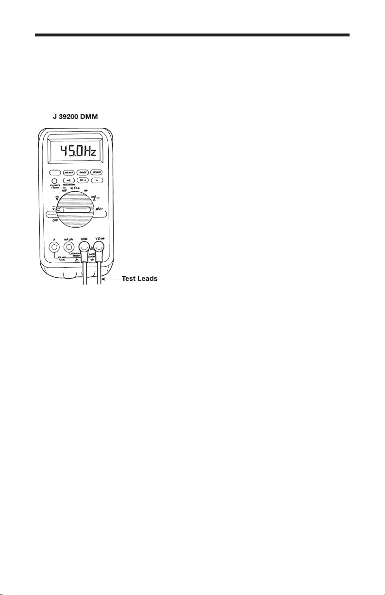
The Fuel Composition Tester
J-44175-A is designed to be used with the
J-39200 Digital Multi Meter (DMM) in order to
display a frequency (Hz) value. This frequency
value is easily converted to indicate ethanol
*During certain atmospheric conditions, it is possible for very small amounts of salty air to enter the vehicle fuel
tank through the evaporative emissions system fresh air vent. If the amount of salt in the fuel becomes
sufficient to light the tester’s red LED, the fuel is contaminated and should be replaced. See “J-44175-A
frequency measures above 160 Hz, and/or the red LED is on” in the appendix.
INTRODUCTION
4