AFL NOYES OLS Series User manual

© 2004-2009, AFL Telecommunications, all rights reserved. COM4-00-1001 Revision E, 2009-06-16
Specifications are subject to change without notice.
OLS Series Light Sources,
OPM Series Optical Power Meters,
and Related Test Kits
User’s Guide

Limited Warranty
One Year Limited Warranty
All Noyes products are warranted against
defective material and workmanship for a
period of one year from the date of shipment
to the original customer. Any product found to
be defective within the warranty period will be
repaired or replaced by Noyes. In no case will
Noyes liabilities exceed the original purchase
price of the product.
Exclusions
The warranty on your equipment shall not apply
to defects resulting from the following:
• Unauthorizedrepairormodication
• Misuse,negligence,oraccident
CE Information
These instruments have been
designed and tested to comply
with the relevant sections of
any applicable specifications including full
compliance with all essential requirements of
allapplicableEUDirectives.
Returning Equipment
To return equipment, please contact Noyes
to obtain additional information and a Service
Request (S.R.) number. To allow us to serve
you more efficiently, please include a brief
description specifying the reasons for the return
of the equipment.
AFL Telecommunications
Noyes
16 Eastgate Park Road
Belmont, NH 03220
Phone: 800-321-5298
603-528-7780
Fax: 603-528-2025

I
Contents
Safety Information
Important Safety Information............................................ III
Section 1: General Information
Contacting Noyes Customer Service................................. 1
UnpackingandInspection................................................ 1
Recommended Accessories ............................................. 2
Section 2: Functional Description
OLS1LEDLightSource ................................................... 3
OPM1 Power Meter ......................................................... 4
Front Panel Features ................................................... 4
DisplayReadings......................................................... 5
Section 3: Applications
Measuring Optical Power................................................. 6
Testing Multimode Links .................................................. 8
Step I - Set the Reference (One Jumper Method).......... 8
Step II - Verify Test Jumpers ....................................... 10
Step III - Measure Multimode Link Insertion Loss .......... 12

II
Section 4: Maintenance
Battery Replacement ....................................................... 14
Cleaning Optical Ports ..................................................... 14
To Clean the OPM1 Optical Port................................... 15
To Clean the OLS1-1C and OLS1-2C Ports ................... 15
Repair and Calibration ..................................................... 16
Section 5: Specifications and Accessories
OLS1LEDLightSourceSpecications ............................. 17
OPM1 Optical Power Meter Specifications........................ 18
Mandrels for Multimode Transmit Jumpers ...................... 19

III
Safety Information
Important Safety Information
WARNING! Useofcontrolsoradjustmentsotherthanthosespeciedhereinmayresult
inhazardousradiationexposure.
The OLS1 optical light source is a CLASS I LED PRODUCT.
WARNING! To avoid the danger of fire and electrical shock:
• NeveruseavoltagethatisdifferentfromthatforwhichtheACadapterisrated.
• Donotplugtheunitintoapoweroutletthatissharedbyotherdevices.
• Nevermodifythepowercordorexcessivelybend,twist,orpullit.
• Do not allow the power cord to become damaged. Do not place heavy objects on
the power cord or expose it to heat.
• NevertouchtheACadapterwhileyourhandsarewet.
• Should the power cord become seriously damaged (internal wiring exposed or
shorted), contact the manufacturer to request servicing.
!
!

IV
WARNING! UseonlythespeciedACadapter.UseofanothertypeofACadaptercan
damage the instrument and create the danger of fire and electrical shock.
CAUTION! To avoid serious eye injury, never look directly into the optical outputs of fiber
optic network equipment, test equipment, patch cords, or test jumpers. Always assume
that optical outputs are on.
NOTICE! Noyes power meters and light sources contain no user serviceable parts. Except
for changing batteries and cleaning optical ports, these units must be returned to Noyes
orauthorizedagentsforrepairandcalibration.
IMPORTANT! Proper care in handling should be taken when using any precision
optical test equipment. Scratched or contaminated optical connectors can impact the
performance of the instrument. It is important to keep the dust caps in place when the
unit is not being used.
!
!
!

1
Section 1: General Information
ThepurposeofthisUser’sGuideistoexplainhowtouseandmaintainNoyestestequipment.
Please check our web site at www.AFLtele.com/go/Noyes for updates to this manual, software
updates, and additional application information. If you have any questions about your instruments
and recommended accessories, or if you need technical or sales support, please contact Noyes
Customer Service.
Contacting Noyes Customer Service
YoumaycallNoyesCustomerServicebetween8a.m.and5p.m.,UnitedStatesEasternTime,
as follows:
Phone: 800-321-5298 (North America)
603-528-7780
Fax: 603-528-2025
E-mail: NoyesTechSupport@AFLtele.com
Unpacking and Inspection
These instruments have been carefully packed in accordance with standard shipping procedures.
Examine the equipment for damage that may have occurred during shipment. If you find any
damage, please contact Noyes.

2
Recommended Accessories
You will need fiber optic test jumpers to connect instruments to the fiber optic system under test.
Atestjumpermusthavethesamecoreandcladdingsizeastheberundertest.Theconnector
at one end of the test jumper must mate with the optical port on each instrument. The connector
on the other end must mate with the fiber optic system under test.
A Connector adapter is required to mate fiber optic test jumpers.
An OPM1 optical port must be equipped with an adapter cap. A variety of adapter caps, connector
adapters, and test jumpers with a variety of lengths and connector styles are available from
AFL - Noyes.
Optical ports and connector end faces must be kept free from dirt or other contaminates to ensure
accurate measurements and operation.
For cleaning connector end faces on OLS light sources, test jumpers, and in fiber frames or
adapters, use optical quality cleaning fluid such as AFL FCC2 connector cleaning fluid and AFL
CCT molded cleaning tips.
For cleaning OPM1 optical ports and adapter caps, use lint-free optical cleaning wipes such as
AFL FiberWipes and optical quality cleaning fluid such as AFL FCC2 connector cleaning fluid (or
IPA-ReagentGradeIsopropylAlcohol99%orbetter)andacanoflteredcompressedair.
Visit our web at www.AFLtele.com/go/Clean for more information.
3
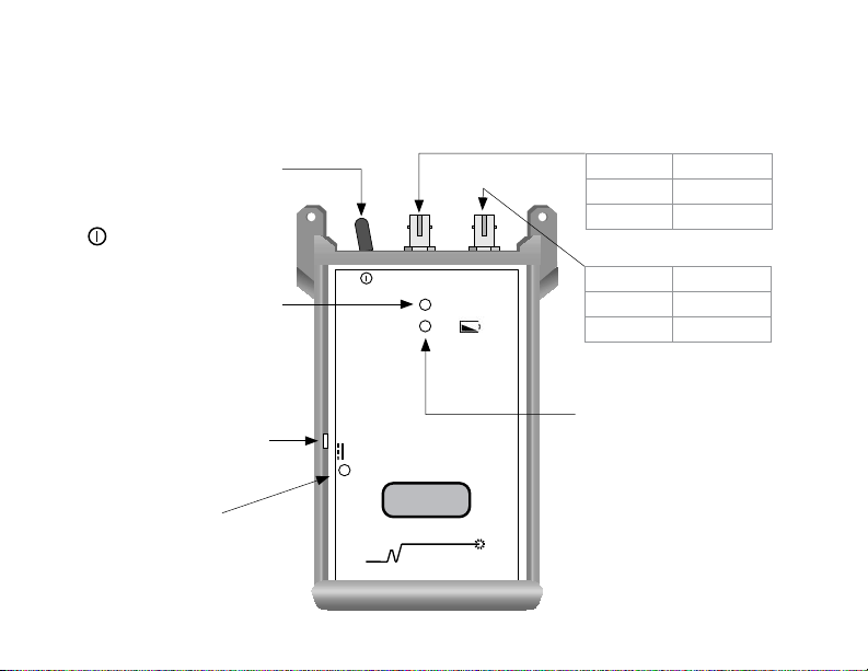
OLS1
9V
850 1300
LED Source
850nm 1300nm
NOYES
AFL Telecommunications
[Wavelength/ Power Off]
switch - selects optical
wavelengths or disables unit
( position).
Power port - Interface for an
AC power adapter.
[Low battery] indicator-
when [ON], indicates a low
battery condition; battery
replacement is required.
Model Output port
OLS1-1C 660 nm
OLS1-2C 850 nm
Model Output port
OLS1-1C 850 nm
OLS1-2C 1300 nm
[Active Output] indicator-
Lights up when one of the
output ports is [ON].
[Power] indicator -
Lights up when the correct
A C p o w e r a d a p t e r i s
connected.
Section 2: Functional Description
OLS1 LED Light Source

4
QSPP
MRPNPdBm
OPTICAL POWER METER
FIBER SYSTEMS
NOYES
OPM 1
nm
AUTO OFF
Power
Optical input - adapter cap
mount
Acce pts Noyes thread- o n
adapter caps.
Adapter cap
The OPM1 must be equipped
with an adapter cap. Adapter
caps for different connector
styles are available from Noyes.
[Power] key
Press to turn unit [On] or [Off].
Unit will turn off automatically
five minutes after the last key
press. To disable the [Auto Off]
feature, press and hold the key
during power up until the letter
[P] appears on the display.
Display
Shows measured power and
calibrated wavelength.
[λ -Wavelength] key
Press to change the calibrated
wavelength. Holding the [λ] key
until the word [HELD] appears
briefly displays the percentage
of battery life remaining.
OPM1 Power Meter
Front Panel Features
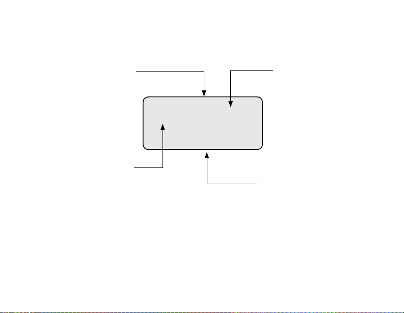
5
AUTO OFF
BAT
-20.0 dBm
nm
1310
[AUTO OFF] indicator
If shown, indicates that the
unit will automatically turn
off five minutes after last key
press. To disable this power-
saving feature, turn the unit
off, then press and hold the
[Power] key until the letter [ P]
appears on the display.
Power reading
Displaysmeasuredpower[dBm].
If power is too high or low for the
OPM1 to measure, this field will
show [HI] or [LO].
[Wavelength] indicator
Disp lays the current l y
selected test wavelength.
[Low battery] indicator
If shown, indicates a low
battery condition. Replace
the battery.
Display Readings

6
!
Section 3: Applications
It is important to keep all optical connections and surfaces free from dirt, oils, or other
contaminants to ensure proper operation. Always clean all test jumpers before conducting
thetestproceduresoutlinedinthisGuide.
Measuring Optical Power
Figure 3-1 illustrates the following procedures.
1 Turn on the OPM1 optical power meter.
2 Select the appropriate fiber optic test jumper. The fiber type of this jumper must be the same
as the fiber type normally connected to the output being measured.
3 Mount the appropriate adapter cap on the OPM1 optical input. This adapter cap must match
the connector on the end of the test jumper you will connect to the OPM1.
4 Connect one end of the test jumper to the OPM1 (adapter cap) and the other end to the optical
output to be measured.
5 Press the λ key to select the calibrated wavelength that matches the nominal wavelength
of the source being measured.
6Read the displayed power measurement (dBm).

7
1300
-20.0dBm
OPTICAL POWER METER
FIBER SYSTEMS
NOYES
OPM 1
nm
AUTO OFF
Power
Output Input
4
3
Figure 3-1: Measuring Optical Power.
Adapter cap
4
Test jumper
Fiber optic equipment
2
6
1

8
Testing Multimode Links
Step I - Set the Reference (One Jumper Method)
Figure 3-2 illustrates the following procedures.
1 Turn on the OPM1 optical power meter and OLS optical light source. Allow the light source to
stabilize(minimumof2minutes).
2 Set both instruments to the desired test wavelength.
3 Select the appropriate fiber optic transmit and receive test jumpers. The fiber type of these
jumpers must match the fiber type of the link to be tested.
4 Wrap and secure the transmit jumper five times around the appropriate diameter mandrel.
Note:Useopticalwipestocleanbothendsofthetransmitjumper.
5 Connect the transmit jumper to the multimode output port of the OLS.
6 Mount an adapter cap on the OPM1 that matches the free connector on the transmit
jumper.
7 Connect the free end of the transmit jumper to the OPM1. The OPM1 will measure and display
optical power in dBm.
8 If measured output power is outside of the normal range (specified by manufacturer), clean
all fiber connections or replace the transmit jumper. Repeat steps 4 - 7.
9 If the displayed power level is acceptable, record it. This is the reference power level at the

9
Figure 3-2: Set the Reference.
OLS OPM1
0 dB
4
5
Transmit jumper
6
7
Mandrel wrap
current wavelength.
Proceed to Step II - Verify Test Jumpers

10
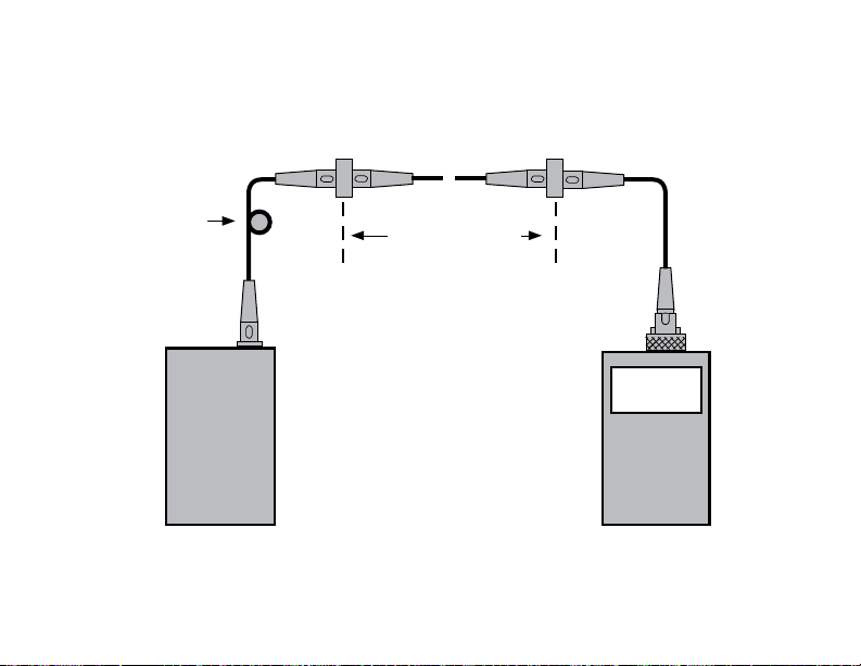
Step II - Verify Test Jumpers
Figure 3-3 illustrates the following procedures.
10 DisconnectthetransmitjumperfromtheOPM1.
Note: DonotdisturbthetransmitjumperattheOLSend.
11 If necessary, change the OPM1 adapter cap to match the connector on the receive jumper
that will be connected to the OPM1.
Note: Useopticalwipestocleanbothendsofthereceivejumper.
12 Connect the receive jumper to the OPM1.
13 Mate the free ends of the transmit and receive jumpers using the appropriate adapter.
14 Record the displayed power level.The difference between the reference power level (from Step
9) and the displayed power level will be the test jumper loss in dB.
Verify that the insertion loss of this mated connector pair is under 0.75 dB, the maximum
allowed by the TIA (Noyes recommends 0.4 - 0.5 dB typical).
If the insertion loss is not acceptable, disconnect the transmit and receive jumpers at the
adapter, clean the free ends of both test jumpers and repeat step 13 & 14.
15 If the insertion loss is acceptable, disconnect the transmit and receive jumpers at the
adapter.
16 Move the OPM1 and OLS to opposite ends of the link to be tested.
Proceed to Step III- Measure Multimode Link Insertion Loss

11
OPM1
0.4 dB
OLS
New adapter cap
(if necessary)
Transmit jumper
Mandrel wrap
Do NOT disturb
this connection
Adapter
Receive jumper
11
12
13
Figure 3-3: Verify Test Jumpers.

12
Step III - Measure Multimode Link Insertion Loss
Figure 3-4 illustrates the following procedures.
17 Connect the free ends of the transmit and receive jumpers to the multimode link under test.
Note: Clean jumper end that connects to patch panel prior to every test.
18 Record the displayed power level.The difference between the reference power level (from Step
9) and the displayed power level will be the link insertion loss in dB.
19 Record link insertion loss at the current test wavelength.
20 Repeat steps 17-19 for all links to be tested at the current wavelength.
13
Figure 3-4: Measure Multimode Link Insertion Loss.
OPM1
OLS
2 dB
~
~
Link under test
Transmit jumper Receive jumper
Patch panelPatch panel
Mandrel wrap

14
Section 4: Maintenance
Battery Replacement
To replace a battery:
1 Remove the protective rubber boot from the instrument.
2 Remove the battery compartment cover located on the back of the instrument.
3 Replace the discharged battery.
4 Replace the battery compartment cover and rubber boot.
Cleaning Optical Ports
CAUTION! Before conducting the following procedures be sure to have the instruments
turned OFF.
Optical ports must be kept free from dirt or other contaminants to ensure accurate measurements
and operation. Always clean all test jumpers before conducting the test procedures outlined in this
Guide.Itisimportanttokeepdustcapsinplacewheninstrumentsarenotbeingused.
For cleaning connector end faces on OLS light sources, test jumpers, and in fiber frames or
adapters,NoyesrecommendsusingourexclusiveFCC2non-hazardouscleaninguidandCCT
molded cleaning tips. For cleaning OPM optical ports and adapter caps, a supply of optical
cleaningwipesandIPA(ReagentGradeIsopropylAlcohol99%orbetter)andacanofltered
!
This manual suits for next models
6
Table of contents
Other AFL Test Equipment manuals

AFL
AFL FlexTester 3 User manual

AFL
AFL MFIS User manual

AFL
AFL FOCIS WiFi2 User manual

AFL
AFL WDM900 User manual

AFL
AFL M710 Series Installation instructions

AFL
AFL ROGUE cB1 User manual

AFL
AFL FlexScan FS300 User manual

AFL
AFL FR1 Series User manual

AFL
AFL Noyes OPM4-3D User manual

AFL
AFL FOCIS Lightning 2 User manual


