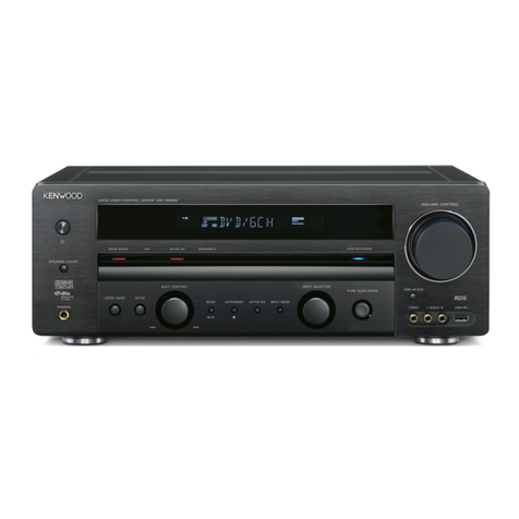
Kenwood KRF-V7300D User manual

This product uses Lead Free solder.
This product complies with the RoHS directive for the European market.
© 2008-8 CREATED IN JAPAN
B53-4048-00 (N/J)PDF
SERVICE MANUAL
AUDIO-VIDEO CONTROL CENTER
KRF-V7300D/V7300D-S
KRF-V8300D/V8300D-S
KRF-V9300D/V9300D-S
VOLUME CONTROL
AV AUX/iPod
VIDEO L-AUDIO-R
SPEAKERS A/B/OFF
PHONES
LISTEN MODE
MULTI CONTROL INPUT SELECTOR
PURE AUDIO MODE
HDMI LINK READY
DTS
DOLBY
DIGITAL
HIGH
DEFINITION
SETUP DOLBY
VIRTUAL
BAND
INPUT MODE
ENTER
STRAIGHT
DECODE
AUTO/MONO
ACTIVE EQ
STRAIGHT
DECODE
Knob
(K29-8591-03): S
(K29-8592-03): B
/
Front glass
(B10-5645-02)
Panel *
(A60-)
Knob *
(K29-)
Foot *
(J02-)
Knob
(K29-8686-02): S
(K29-8687-02): B
Phone jack
(E11-1019-05)
Knob
(K29-8686-02): S
(K29-8687-02): B
Knob
(K29-8680-03): S
(K29-8681-03): B
Knob
(K29-8682-03): S
(K29-8683-03): B
Knob
(K29-8684-03): S
(K29-8685-03): B
Pin jack
(E63-1388-05)
L
R
AUX CD MD/TAPE VIDEO1
ANTENNA
VIDEO2
AUDIO
DVD/6CH IN
FRONT SPEAKERS (6 – 16 )
AUTO ROOM EQ
MIC IN
VIDEO1 IN VIDEO1 IN
MONITOR OUT
MONITOR OUT
DVD IN
DVD IN
VIDEO2 IN
VIDEO1 OUT
CD(ASSIGNABLE)
SUB WOOFER
PRE OUT
VIDEO2 DVD DVD IN
OPTICAL
CENTER
SURROUNDFRONTPLAY INPLAY INREC OUTPLAY INPLAY INPLAY IN REC OUT
SUB WOOFER
OPTICAL COAXIAL
VIDEO2 IN
MONITOR OUT
HDMIDIGITAL IN
S-VIDEO
VIDEO COMPONENT VIDEO
+
–
+
–
RED WHITE GRAY BLUEGREEN TAN BROWN
AM
SPEAKER A SPEAKER B CENTER SURROUND SURROUND BACK
GND FM 75
5V 500mA
iPod
YCB CR
VIDEO2 IN
YCB CR
L
RL
RL
RL
R
SURROUND SPEAKERS (6 – 16 )
Metallic cabinet
(A01-3995-01): S
(A01-3996-01): B
Pin jack
(E63-1338-05) x 2
Pin jack
(E63-1407-05)
Pin jack
(E63-1380-05)
Pin jack
(E63-1417-05)
Pin jack
(E63-1146-15)
Phone jack
(E11-0962-05)
Rectangular
receptacle
(E58-0095-05)
Optical receiving
module
(W02-4652-05) x 2
Pin jack
(E63-1428-05)
Rectangular receptacle
(E58-0100-05) x 3
Tuner
(W02-4644-05)
Screw terminal board
(E70-1018-05) x 2
Pin jack
(E63-1371-05)
Cylindrical receptacle
(E56-0065-05)
Screw terminal board
(E70-1009-05)
Screw terminal
board
(E70-1018-05)
Pin jack
(E63-1374-05) x 2
AC power cord *
(E30-)
B: Black panel
S: Silver panel
Illustration: KRF-V9300D
* Refer to parts list on page 68.

2
KRF-V7300D/V8300D/V9300D
FM indoor antenna (1)
(T90-0854-05)
AM loop antenna (1)
(T90-0893-05)
Remote control unit (1)
- KRF-V9300D : RC-R0923 (A70-1736-05)
- KRF-V8300D : RC-R0831 (A70-1731-05)
- KRF-V7300D : RC-R0733 (A70-1730-05)
Batteries * (R03) (2)
(-)
* Batteries are attached to
the packing material.
KRF-V9300D /KRF-V8300D only
Setup microphone (Cord length : About 5m) (1)
(T29-0011-05)
ACCESSORIES / iPod MODELS USABLE WITH THIS UNIT
• To connect an iPod, you will need the iPod connection cable
PNC-iP120 (optional accessory).
• This unit does not come with an iPod. It is up to you to
purchase an iPod separately.
• Controllable iPod (As of July 2008)
Controllable iPod
iPod 4th Generation (Click wheel)
iPod mini
iPod 4th Generation (Color display)
iPod nano 1st Generation
iPod nano 2nd Generation
iPod video (iPod 5th Generation)
iPod photo
iPod nano 3rd Generation
iPod classic
iPod touch*
* With iPod touch, only the "Music" is compatible.
• Update the software of your iPod to the latest version. The
latest iPod software upgrading data can be downloaded from
the website of Apple Inc.
• Some functions of iPod may not work properly depending on
the iPod models and the software version.
• This unit supplies power to your iPod, which means you can
enjoy listening to music while charging your iPod. To do this,
the unit must be turned on.
• Video output setting of iPod such as "TV OUT" and "TV Signal"
needs to be set on your iPod.
Handling precautions
• Be sure to read the instruction manual that comes with the
iPod you are using.
• Certain conditions while using an iPod can cause contents
stored on the iPod to be lost. Note that Kenwood will not be
held liable for any losses arising out of loss of stored contests.
Displayble characters
• This unit can display alphanumeric and some symbol
characters.
It displays accented characters after converting them into
ordinary alphabet characters. The non-displayable characters
are displayed as "*".
B60-57400000EN.indd7 08.7.115:45:41PM
Accessories iPod models usable with this unit

3
KRF-V7300D/V8300D/V9300D
Resetting the Microcomputer
If the unit is completely inoperable, the display is not normal or a problem cannot be solved even after checking the list in
<Troubleshooting>, it is required to reset the microcomputer in the unit.
While holding down [ ] key on the unit, unplug the power cord and plug it back in.
• Please note that resetting the microcomputer will clear the contents of the memory and return the unit to the state it was in when it left the
factory.
B60-57400000EN.indd68 08.7.115:46:56PM
RESETTING THE MICROCOMPUTER

4
KRF-V7300D/V8300D/V9300D
BLOCK DIAGRAM
J391
J301
IC391
IC321
L/R
MIC (R,EQ)
AV AUX
L/R
AM/FM
TUNER
J301
J301
J311
J311
J321
J311
J311
J341
: W02-4644-05
: W02-4689-05
J701
+6.8dB
IC111 E.VOL AVR
+4dB
+10dB
+10dB
+10dB
IC131,181
IC191
IC131,181
IC171
AVR
+24dB
+36.0dB
PACK
POWER AMP.
DISCRETE
+24dB
PACK
PACK
+24dB
6dB
Q1,2
Q3,4
Q5,6
Q101
Q7,8 CLASS A
K1
K2
K3
K5
RELAY SW
K4
K6
RX DETECT
SENSE IDENTIFY
Q381,382
Q835,836
J301
J311
J361
Q306,363
ANALOG AUDIO OUTPUT
i-pod
MD/TAPE
L/R
VIDEO1
L/R
SUB WOOFER
PRE-OUT
AUX L/R
CD/DVD
L/R
MD/TAPE
L/R
VIDEO1
L/R
VIDEO2
L/R
FL/FR
C/SW
SL/SR
DVD/6CH INPUT
ANALOG AUDIO INPUT
IC111
+20.8dB
IC503
AV AUX
J301 (X14)
J881
VIDEO1
J901
J901
DVD
VIDEO2
MONITOR
J901
J881
VIDEO1
COMPOSIT VIDEO
INPUTOUTPUT
IC901
NJM2279
NJM2595
NJM2279
IC904
IC902
J901
VIDEO2
J901
DVD
J901
MONTTOR
S VIDEO
OUTPUT INPUT
E2PROM
IC204
IC506
R
ML86V7656
ML86V7668A
Y DET.
J931
VIDEO1
J932
VIDEO2
DVD
MONITOR
COMPONENT VIDEO
OUTPUT INPUT
IC801 IC802
MN101EF16KXW
RAM : 12KB
ROM : 256KB
IC931 IC880
X34HDMI
KRF-V9300D
KRF-V8300D,
Y DET.
ATT
(J)
(E,X)
IC505
-6dB
Q423,424
R2S15205FP
HDMI
DECODE
DIFINITION
DOLBY
DTS
IC402,403
Q411
MICRO PROCESSOR
C
Y
NJM2586 NJM2586
J931
J932
D751-758
J981 (J)
J982 (J)
J981 (J)
J982 (J)
12V
12V
+9V
220
220
220
220
220
220
220
220K
220
220K220K
220
AUDIO
VIDEO COMPOSIT
TX
DO SD
RDS DATA
RDS CLK
D IN
CLK CE
REC L/R
L/R
C
SBL/SBR
LFE
SL/SR
FL/FR -12V
+12V
+7.0V
-7.0V
FL/FR
SL/SR
C/SW
SWF
C
SBL/SBR
LIMITTER
HP.IN
PROTECT
PROTECT
OVER CURRENT
DC VOLTAGE
FRONT LEVEL
SURROUND LEVEL
220
220
REC OUT MUTE
1.5K
33K
3.3K
75
75
75
V IN2
V IN3
V IN4
V IN5
75
V IN1
+5V
-5V
V OUT1
V OUT2
V OUT3
+12V
+5V
+7.5V
-5V
-12V
-5V
+5V
+5V
-5V
V IN3
V IN2
V IN1
V IN2
V IN1
V IN3
V OUT1
V OUT2
V OUT2
V OUT1
75 75
75 7575
75 75
C
Y
Y
C
C
Y
BUSY
DATA
+3.3V
RESET CE
CEC CONT. x
2
HDMI CONT. x
DSP CONT. x
4
RELAY CONT.
x
THERMAL PR
O
AVR PROTEC
T
+3.3V
Y ( 7 : 0 )
+2.5V +3.3V +2.5V +3.3V
Y
Cb
Cr
SC
SY
X3
75 x 375 x 3
X3
75 x 3
X3
75 x 3 CH2 IN3
GND
CH2 IN2
GND
V+1
CH2 IN1
CH1 IN3
CH1 IN2
SW2
SW1
CH1 IN1
+5V
CH3 IN3
CH3 IN1
V+2
CH3 IN2
GND
V-1
PS
CH1 OUT
CH3 OUT
CH2 OUT
V+2
-5V
CH2 IN2
GND
CH2 IN3
V+1
CH2 IN1
GND
CH1 IN3
SW2
CH3 IN2
GND
CH3 IN3
CH3 OUT
CH3 IN1
V+2
V+2
V-1
+5V
CH1 IN1
CH1 IN2
SW1
CH1 OUT
CH2 OUT
PS
-5V
10.0MHz
SDARST,SLC
V CONT1,2,3
DSP & HDMI
X34 BOARD
from
F. OFF
SCK
SDATA
CS
PURE
ST-BY
X09 (AMP,AVR)
X14 (DISPLAY,PRIMARY)
X08-1 (E-VOL,u-COM)
KRF-V9300D/V9300H-S
KRF-V8300D,
X08-2 (ANALOG VIDEO)
(J) (E,X)

5
KRF-V7300D/V8300D/V9300D
K1
K2
K3
K5
R
ELAY SW
K4
K6
HEAD PHONES
SPEAKER A L/R
SPEAKER B L/R
SPEAKER
SPEAKER
SPEAKER
J101 (X14)
J5
J6
J7
J7
J8
FAN AVR F09-0192-05
DC FAN
RESET
IC784
IC1
M66005-0001AHP
IC3
SURROUND BACK L/R
CENTER
SURROUND L/R
IC783 (X08)
-12V
IC402
IC404
-35V
+4.1V
(J)
(E,X)
SUB. TRANS.
: L07-3372-05
: L07-3373-05
D802
D801
D502-504
D401
D403
D205-208
D201,202
IC401
(X08)
Q203
Q202
Q201
Q407
+5V
+5V
+12V
IC4
+9V
Q801
K801
D419-422
K201
Q405
T201
CONTROL
REMOTE
KEY IN 1,2
D1
D2
A1
ED1
S16
INPUT SEL. MULTI CONT.
S15
VOLUME CONT.
S301
X14
J1
LPF,fc=96kHz
LPF,fc=96kHz
LPF,fc=96kHz/200Hz
LPF,fc=48kHz
FL/FR ch
Cch
LFEch
SL/SRch
REC L/Rch
SBL/SBRch
ANALOG IN L/R
AK4589VQ
IC301
GP1FAV51RK0F
GP1FAV51RK0F
McASP0
RAM
ROM
MEMORY
C67x +TM
INSTRUCTION
CROSSBAR SWITCH
EMIF dMAX
PLL OSC
32-/64-Bit
DSP CORE
FLOATING-POINT SPL1
I
McASP2
McASP1
32-Bit COUNTER
SPI0
RTI
CACHE
(DMA)
CONTROLLER
D788E001BRFP
IC401
MICRO PROCESSOR
MN101EF16KXW
HDMI & DSP CONTROL
IC11
GENERATOR
CLOCK
16M
FLASH MEMORY
64M
SD RAM
A29L160A1CHB
EM484M1644VB6
IC451
IC461 X351
IC351
24.576MHz
HDMI OUT HDMI IN1HDMI IN2
EDID
CEC
BUFFER EDID
J503 J502 J501
Q503 Q502 Q501
SII9135CTU
HDMI RX
SILICON IMAGESILICON IMAGE
SII9134CTU
HDMI TX
IC501IC502
SYSTEM u-COM
X501
MN101EF16KXW
MICRO PROCESSOR
X502
IC503
FLASH DEBUG
WRITE
ABT1012
ANCHOR BAY
VIDEO SCALER
IC702
VIDEO ADC
ANALOG DEVICES
ADV7401BSTZ80
IC701
5V AVR
IC506
3.3V AVR
IC511
IC504
1.8V AVR
1.8V AVR
IC505
EDID
u-COM
HDMI RX/TX
HDMI RX
HDMI TX
IC101,111
IC131,141
IC161,171
IC191,201,208
DVD
COAXIAL
OPTICAL
CD
OPTICAL
VIDEO2
PCM/Bit-STREAM
DIGITAL AUDIO INPUT
16-BT-152GNK
LED
A2
A2
TMS320DA708 FLOATING POINT DSP
8.00MHz
X11
28.322MHz
19.800MHz
CN501
CN502
CN103
C0
IC1
HP.IN 32
6
6
6
6
6
RESET CE
CEC CONT. x 2
HDMI CONT. x 4
DSP CONT. x 4
FAN CONT.
RELAY CONT. x 8
THERMAL PROTECT x 4
AVR PROTECT
to X34 HDMI
to X34DSP
-BV
HI/LO
10.0MHz
-35V +3.3V
VIDEO CIRCUIT
for ANALOG
TUNER
for
for HDMI
for DSP
or USB
for iPod
FL -VFL
FL FILAMENT
(E,X)
(J)
FUSE
: 3.15A
: 8A
POWER
RELAY
DETECTOR
AC OFF
(F.OFF)
50/60Hz
: AC100V
: AC230V~ 50Hz
: AC240V~ 50Hz(X)
(E)
(J)
RELAY
HI/LO TAP
AMPLIFIER
for POWER
for
FAN
PACK
MAIN TRANS.
(E)
(J)
(X)
: L07-3382-05
: L07-3383-05
: L07-3384-05
+3.3V
BACK UP +4.1V
+5.0V
ENCODER
75
24bit 192kHz DIR & DIT
8 INPUT, 2 OUTPUT
SAMPLING FREQUENCY : max. 96kHz
2ch 24bit ADC
SAMPLING FREQUENCY : max. 192kHz
8ch 24bit DAC
-6dB
+3dB
+3dB
LEF : +7.5dB
C : +3dB
+5V+3.3V
470
470
+3.3V +1.2V
+3.3V
TMDS
DDC
HP
+5V
+5V
DDC
TMDS
HP
HP
TMDS
DDC
+5V
AUDIO DATA
VIDEO DATA
I2C,RST,INT
I2C,RST
5V
5V
3.3V
1.8V
1.8V
HDMI 7V
HDMI 5V
F201
F. OFF
PURE
ST-BY
for ANALOG
AUDIO CIRCUIT
for ANALOG
VIDEO CIRCUIT
AUDIO
SEL
2
2
KRF-V9300D
X34 (DSP)
X34 (HDMI)
X14 (DISPLAY,PRIMARY)
BLOCK DIAGRAM

6
KRF-V7300D/V8300D/V9300D
●Semiconductor Working Description (X08-3502-70)
Ref. No. Parts No. Description Logic
D207,208 1SS402-F The protection for the input of IC204 from static electricity.
D301 1SS302-F The protection for the circuit from static electricity.
D311 1SS302-F The protection for the circuit from static electricity.
D391 UDZW4.7 (B) The power supply for the MIC circuit.
D392,393 UDZW18 (B) The protection for the input of IC204 from static electricity.
D401 UDZW3.9 (B) The power supply for the protection circuit.
D402 1SS355 The protection for the protection circuit from the reverse current.
D403 UDZW5.6 (B) The detection of over voltage for digital +5V.
D404 1SS355 The protection for the protection circuit from reverse current.
D405 1SS355 Adjusting voltage of protection detection voltage.
D406 1SS355 The protection for the protection circuit from reverse current.
D407 1SS355 The protection for the microprocessor power supply from reverse
current.
D408 1SS355 The protection for Q403.
D409 UDZW11 (B) The power supply for FAN circuit.
D410 UDZW6.2 (B) The power supply for FAN circuit.
D411 UDZW5.6 (B) The power supply for FAN circuit.
D412 UDZW5.2 (B) The power supply for FAN circuit.
D413 1SS355 The protection for the microprocessor power supply from reverse
current.
D414 1SS355 The level shifter for Q407.
D415,416 1SS355 The level shifter for fast-off detection circuit.
D418 1SS355 The protect the circuit from static electricity.
D419 UDZW3.3 (B) The power supply for analog mute and REC mute.
D420,421 1SS355 The protection for the power supply of analog mute and REC mute
from reverse current.
D422 UDZW6.2 (B) The power supply for IC204 ±7.0V
D423,424 1SS355 The protection for the power supply of analog mute and REC mute
from reverse current.
D425 UDZW3.3 (B) The power supply for analog mute and REC mute.
D426 UDZW3.3 (B) The control video circuit (X08) on/off. power on/off.
D427 UDZW8.2 (B) The power supply for video circuit. +7.5V
D428 UDZW6.2 (B) The power supply for IC204 ±7.0V
D501 1SS355 The protection for the protection circuit from reverse current.
D502 1SS355 The protection for the OR circuit of analog mute from reverse current.
D701 1SS302-F The protection for the circuit from static electricity.
D709 1SS302-F The protection for the circuit from static electricity.
D881 1SS302-F The detection for video synchronizing signal.
D901 1SS302-F The detection for video synchronizing signal.
IC111 NJM4565MD-ZB The buffer amplifier of IC204 (OP amp)
IC131 NJM4565MD-ZB The buffer amplifier of IC204 (OP amp)
CIRCUIT DESCRIPTION

7
KRF-V7300D/V8300D/V9300D
Ref. No. Parts No. Description Logic
IC171 NJM4565MD-ZB The buffer amplifier of IC204 (OP amp)
IC181 NJM4565MD-ZB The buffer amplifier of IC204 (OP amp)
IC191 NJM4565MD-ZB The buffer amplifier of IC204 (OP amp)
IC204 R2S15205FP The electronic volume (Selector and volume)
IC391 NJM4565MD-ZB The Mic amp (OP amp)
IC401 XC62HR4102PRN The regulator for IC506. +4.1V
IC402 KIA78R05PI-P The regulator for video circuit. +5V
IC403 KIA79R05PI-P The regulator for video circuit. -5V
IC501,502 TC74HCT7007FF The hex buffer (3V to 5V level shifter ; tuner, FL driver, electronic
volume).
IC503 MF1341S2160 iPod coprocessor.
IC505 M24C08-RDW6TP EEPROM
IC506 MN101EF16K1CLA The system control microprocessor.
IC507 NJU3718AM-ZB The converter from serial to parallel (LED, SPEAKER RELAY,VIDEO
SELECTOR)
IC651~653 BA2903F The comparator for thermal protection.
IC701 MIC2005-05YM6 The high-side switch (detection of over current; more 700mA
IC702 NJM4565MD-ZB The audio amp for iPod (OP amp)
IC782 XC6201P332PRN The regulator for logic circuit. +3.3V
IC783 NJM2830U109ZB The regulator for tuner. +9V
IC784 XC61CN2702MRN The voltage (2.7V) detection for microprocessor reset.
IC801 ML86V7668AT03 The video decoder (Analogue video up converter).
IC802 ML86V7656T03 The video encoder (Analogue video up converter).
IC803 74AHC1GU04GW The inverter for oscillation (32MHz) circuit.
IC804 NJM2820F-ZB The shunt regulator for reference voltage (1.25V) of video encoder.
IC811 XC6203P332PRN The regulator for video decoder and encoder. +3.3V
IC812 XC6214P252PN The regulator for video decoder and encoder. +2.5V
IC880 NJM2586AM-ZB The video amp for component signal selector and buffer amp.
IC881 NJM4565MD-ZB The detection of video synch signal.
IC901,902 NJM4565MD-ZB The video amp for S-video signal selector and buffer amp.
IC903 NJM4565MD-ZB The detection of video synch signal.
IC904 NJM4565MD-ZB The video amp for composite signal selector and buffer amp.
IC931 NJM2586AM-ZB The video amp for composite signal selector and buffer amp.
IC981,982 CD4052BPWR The analog switch (selector of D jack)
Q306 2SC4213 (B) -F The mute for Super Woofer (SW) pre-out. Mute: ON
Q363 2SC4213 (B) -F The mute for Super Woofer (SW) pre-out. Mute: ON
Q381,382 2SC4213 (B) -F The mute for rec-out Mute: ON
Q385,386 2SC4213 (B) -F The mute for rec-out Mute: ON
Q391 DTA143TSA The control of mic amp. AUTO ROOM EQ: ON
Q401 2SA1576A (R,S) The protection for AVR.
Q402 2SC4081 (R,S) The protection for AVR.
CIRCUIT DESCRIPTION

8
KRF-V7300D/V8300D/V9300D
Ref. No. Parts No. Description Logic
Q403 2SC4081 (R,S) The inverter of reset signal.
Q404 2SC4081 (R,S) The protection for AVR.
Q405 2SB 1640-Q The power supply for FAN.
Q406 2SC4081 (R,S) The protection for AVR.
Q407 2SA1576A (R,S) The control of FAN motor. Low turns: ON
Q408 2SC4081 (R,S) The control of FAN motor. High turns: ON
Q409 2SA1576A (R,S) The fast power-off detection.
Q410 2SA1576A (R,S) The control for analog mute and Rec-out mute. Mute: ON
Q411 2SA1576A (R,S) The control power supply for video circuit.
Q412 2SC4081 (R,S) The control power supply for video circuit.
Q413 2SA1576A (R,S) The control power supply for video circuit.
Q414 DTC124EUA The control power supply for video circuit.
Q415 2SC4081 (R,S) The power supply for IC204 ±7V
Q416 2SA1576A (R,S) The power supply for IC204 ±7V
Q417 2SA1576A (R,S) The control for power supply of video circuit.
Q418 2SC4081 (R,S) The power supply for IC204 ±7V
Q419,420 2SA1576A (R,S) The power supply for IC204 ±7V
Q421 2SC4081 (R,S) The power supply for IC204 ±7V
Q422 2SA1576A (R,S) The control for analog mute and Rec-out mute. Mute: ON
Q423 2SC1627-F(Y) The power supply for IC204 ±7V
Q424 2SA817-F(Y) The power supply for IC204 ±7V
Q425,426 2SK879-F(Y,GR The constant current for IC204 ±7V
Q427 2SC4081 (R,S) The power supply (+7.5V) for video circuit.
Q428 2SA1576A (R,S) The protection for AVR.
Q651 2SA1576A (R,S) The protection for thermal protection.
Q701 DTC124EUA The control for DSP mute (analog mute). Mute: ON
Q702 DTC124EUA The control for tuner power supply. Tuner: ON
Q703 2SA1576A (R,S) The control for tuner power supply. Tuner: ON
Q750 2SC4081 (R,S) The control for LED LED on: ON
Q751 DTC124EUA The control for LED dimmer Dimmer: ON
Q752 2SC4081 (R,S) The control for LED LED on: ON
Q753 DTC124EUA The control for LED dimmer Dimmer: ON
Q754 2SC4081 (R,S) The control for LED LED on: ON
Q755 DTC124EUA The control for LED dimmer Dimmer: ON
Q756 2SC4081 (R,S) The control for LED LED on: ON
Q757 DTC124EUA The control for LED dimmer Dimmer: ON
Q758 2SC4081 (R,S) The control for LED LED on: ON
Q759 DTC124EUA The control for LED dimmer Dimmer: ON
Q760 2SC4081 (R,S) The control for LED LED on: ON
Q761 DTC124EUA The control for LED dimmer Dimmer: ON
Q801 2SC4081 (R,S) The buffer amplifier of composite signal.
CIRCUIT DESCRIPTION

9
KRF-V7300D/V8300D/V9300D
Ref. No. Parts No. Description Logic
Q881 2SC4081 (R,S) The level shifter of video synch detection.
Q902 2SC4081 (R,S) The level shifter of video synch detection.
Q903 DTA124EUA The detection of the S terminal video signal and control video
selector IC.
Q981-983 2SC4081 (R,S) The buffer amplifier of video component signal.
Q984-986 DTC124EUA The level shifter of video selection control signal
Q987 DTA124EUA The level shifter of video selection control signal
●Semiconductor Working Description (X09-7052-70)
Ref. No. Parts No. Description Logic
D1~9 1SS133 The base voltage pull-down for muting transistors,Q1~8 and Q101.
D203 1SS133 The temperature compensation for Q207.
D204 1SS133 The temperature compensation for Q208.
D205 1SS133 The current mirror.
D206 1SS133 The current mirror.
D209 UDZW8.2 (B) +9 power supply.
D210 UDZW8.2 (B) -9 power supply.
D301 UDZW3.3 (B) The voltage for mute control.
D302 UDZW3.3 (B) +3.3V power supply for microprocessor.
D304 DAN202U The OR circuit of power supply.
D305 UDZW3.3 (B) +3.3V power supply for protection control.
D306 1SS133 The protection Q305 control.
D307 1SS133 The protection Q305 control.
D308 1SS133 The detection level for FAN control. C-ch
D309 DAN202U The detection level for FAN control. S L and SB L-chs
D310 DAN202U The detection level for FAN control. S R and SB R-chs
D311 1SS133 The detection level for limiter control. S R-ch
D312 1SS133 The detection level for limiter control. C-ch
D314 DAN202U The detection level for limiter control. F L and F R-chs
D315 DAN202U The detection level for FAN control. F L and F R-chs
D316~321 1SS133 Protect the relay from reverse current.
D322 1SS133 The detection level for limiter control. S L-ch
D502~505 1SR139-400T64 +12V rectifier.
D516 UDZW13 (B) The power supply (+B) for 2nd and 3rd stages of main amp circuit.
D517 UDZW15 (B) The power supply (+B) for 2nd and 3rd stages of main amp circuit.
D518 UDZW8.2 (B) The power supply (-B) for 2nd and 3rd stages of main amp circuit.
D519 UDZW5.6 (B) The power supply (-B) for 2nd and 3rd stages of main amp circuit.
D520 UDZW18 (B) The power supply (-B) for 2nd and 3rd stages of main amp circuit.
D521 UDZW24 (B) The power supply (-B) for 2nd and 3rd stages of main amp circuit.
D523 1SS355 Protect the Q510 from reverse current.
CIRCUIT DESCRIPTION

10
KRF-V7300D/V8300D/V9300D
Ref. No. Parts No. Description Logic
D524 1SS355 Protect +12V tap of the power transformer.
D525 1SS355 Protect -12V tap of the power transformer.
D526,527 1SS355 The detection of short circuit 12V taps.
D801 TS6P03G-B The low voltage taps rectifier.
D802 TS6P03G-B The high voltage taps rectifier.
D803,804 1SR139-400T64 The diode for the tap selector relay.
D805 1SS355 Protect the relay from reverse current.
IC1 STK433-330-E 3-ch power pack IC. C-ch, S R-ch and SB R-ch
IC2 STK433-130-E 2-ch power pack IC. S L-ch and SB L-ch
IC3 KIA7812API-UP +12V regulator IC for analog circuit.
IC4 KIA7912API-UP -12V regulator IC for analog circuit
Q1 DTC643TU -6dB attenuator. L-ch
Q2 DTC643TU -6dB attenuator. R-ch
Q3 2SC2878 (B) -F For muting L-ch
Q4 2SC2878 (B) -F For muting R-ch
Q5 DTC643TU For muting S L-ch
Q6 DTC643TU For muting S R-ch
Q7 DTC643TU For muting SB L-ch
Q8 DTC643TU For muting SB R-ch
Q101 DTC643TU For muting C-ch
Q201 2SK364F (GR,BL) The 1st stage differential amp. L-ch
Q202 2SK364F (GR,BL) The 1st stage differential amp. R-ch
Q203 2SC4081 (R,S) The constant current for the 1st stage of amp. L-ch
Q204 2SK364F(GR,BL) The 1st stage differential amp. R-ch
Q205 2SK364F(GR,BL) The 1st stage differential amp. L-ch
Q206 2SC4081 (R,S) The constant current for the 1st stage of amp. R-ch
Q207 IMX8 The 2nd stage amp. L-ch
Q208 IMX8 The 2nd stage amp. R-ch
Q209 2SA970-F (BL) The 3rd stage amp. L-ch
Q210 2SA970-F (BL) The 3rd stage amp. R-ch
Q211 2SA970-F (BL) The current mirror. L-ch
Q212 2SA970-F (BL) The current mirror. R-ch
Q213 2SA970-F (BL) The current mirror. L-ch
Q214 2SA970-F (BL) The current mirror. R-ch
Q215 2SA970-F (BL) The 3rd stage amp. L-ch
Q216 2SA970-F (BL) The 3rd stage amp. R-ch
Q217 TRAIT10N The power transistor. L-ch
Q218 TRAIT10N The power transistor. R-ch
Q219 TRAI1T10P The power transistor. L-ch
Q220 TRAIT10P The power transistor. R-ch
Q221 2SC2240-F (BL) The current protection. L-ch
CIRCUIT DESCRIPTION

11
KRF-V7300D/V8300D/V9300D
Ref. No. Parts No. Description Logic
Q222 2SC2240-F (BL) The current protection. R-ch
Q223 2SK879-F (Y,GR) The constant current for the 1st stage of amp. L-ch
Q224 2SK879-F (Y,GR) The constant current for the 1st stage of amp. R-ch
Q225 2SC4081 (R,S) The constant current for the 1st stage of amp. L-ch
Q226 2SC4081 (R,S) The constant current for the 1st stage of amp. R-ch
Q227,228 2SC4081 (R,S) +9V power supply.
Q229,230 2SC4081 (R,S) -9V power supply.
Q301 2SA1576A (R,S) -6dB attenuator.
Q302 2SA1576A (R,S) The mute control.
Q303 2SC4081 (R,S) The protection control.
Q304 2SC4081 (R,S) The protection control.
Q305 2SA1576A (R,S) The protection control.
Q306 2SC4081 (R,S) The protection control.
Q307 2SC4081 (R,S) The protection control.
Q308 2SA1576A (R,S) The protection control.
Q309 2SC2240-F (BL) The current protection. SB R-ch
Q310 2SC2240-F (BL) The current protection. SB L-ch
Q311 2SC2240-F (BL) The current protection. C-ch
Q312 2SC2240-F (BL) The current protection. S R-ch
Q313 2SC2240-F (BL) The current protection. S L-ch
Q314 DTC113ZUA The headphone relay control.
Q315 DTC113ZUA The front speaker-A relay control.
Q316 DTC113ZUA The front speaker-B relay control.
Q317 DTC113ZUA The center speaker relay control.
Q318 DTC113ZUA The surround speaker relay control.
Q319 DTC113ZUA The surround back speaker relay control.
Q505 2SA1576A (R,S) -B voltage limiter control for the 2nd and 3rd stages amp. -B power supply selector
Q506 2SD2525-Q +B voltage control for the 2nd and 3rd stages amp.
Q507 2SB1640-Q -B voltage control for the 2nd and 3rd stages amp.
Q508 2SK879-F (Y,GR) The constant current circuit.
Q509 2SK879-F (Y,GR) The constant current circuit.
Q510 2SC4081 (R,S) -B voltage limiter control for the 2nd and 3rd stages amp. Q505
Q511 2SA1576A (R,S) -B constant voltage for the 2nd and 3rd stage amp.
Q512 2SC4081 (R,S) +B constant voltage for the 2nd and 3rd stage amp.
Q513 2SC4081 (R,S) The Darlington connection for Q506.
Q514 2SC4081 (R,S) The Darlington connection for Q507.
Q515 2SC4081 (R,S) The protection works when shorted between AC (+12V) and GND. Q515-off: protection-on
Q516 2SC4081 (R,S) The protection works when shorted between AC (-12V) and GND. Q516-off: protection-on
Q801 DTC124EUA The power supply voltage selector (HIGH or LOW tap) HIGH: Q801-on
CIRCUIT DESCRIPTION

12
KRF-V7300D/V8300D/V9300D
●Semiconductor Working Description (X14-8112-70)
Ref. No. Parts No. Description Logic
D1 B30-2597-05 STANDBY LED (RED)
D2 B30-2702-05 PURE AUDIO MODE LED (WHT)
D3 1SS302-F Protect the rotary encoder (LISTEN MODE) from static electricity.
D4 1SS302-F Protect the rotary encoder (MULTI CONTROL) from static electricity.
D5 1SS302-F Protect the rotary encoder (INPUT SELECTOR) from static electricity.
D9 1SS355 Drop the voltage for remote control receiving device.
D10 UDZW6.8 (B) For cutoff bias of FL.
D11 1SS355 Protect circuit between digital +5V and GND from the reverse current.
D12 1SS355 Protect circuit between FL -30V and GND from the reverse current.
D201,202 1SS355 Rectifier diodes for reset circuit.
D203 1SS302-F Constant current for power relay (1.2V up)
D204 1SS355 Protect the power relay from the reverse voltage.
D205~208 1SS355 Rectifier diodes for small transformer.
D301,302 1SS302-F Protect the FRONT AUX circuit from static electricity.
D401 TS4B03G-B1 Stacked rectifier diode for DSP
D402 TS6P03G-B Stacked diode for HDMI
D403 TS4B03G-B1 Stacked diode for iPod.
D404 1SR139-400T64 Protect the microprocessor from the reverse current.
D405 1SS302-F Protect the microprocessor from connecting power supply (DSP’s
regulator) suddenly.
D406 1SS302-F Protect the microprocessor from connecting power supply (DSP’s
transformer) suddenly.
D407,408 UDZW16 (B) 16V zener diode for FL power supply (-30V)
D409 1SR139-400T64 Protect the microprocessor from the reverse current.
D410 UDZW4.7 (B) For voltage adjustment of microprocessor protection.
D411 UDZW8.2 (B) Protect the circuit of DSP (+5V).
D412 1SS355 Protect the circuit of DSP +5V.
D413 UDZW8.2 (B) Protect the circuit of HDMI (+7V).
D414 1SS355 Protect the circuit of HDMI +7V.
D415 UDZW8.2 (B) Protect the circuit of HDMI (+5V).
D416 1SS355 Protect the circuit of HDMI +5V.
D419~422 1SR139-400T64 Rectifier diode for FL (-30V).
D423~426 1SR139-400T64 Rectifier diode for analog circuit (±12V).
D427 1SS302-F Protect the microprocessor from connecting power supply (HDMI’s
transformer) suddenly.
D428 1SS302-F Protect the microprocessor from connecting power supply (HDMI’s
regulator) suddenly.
D429 1SS302-F Protect the microprocessor from connecting power supply (FL’s
circuit) suddenly.
D430 1SS355 Protect the circuit of FL -30V.
D431 1SS355 Protect the circuit of analog +B.
CIRCUIT DESCRIPTION

13
KRF-V7300D/V8300D/V9300D
Ref. No. Parts No. Description Logic
D432 1SS355 Protect the circuit of analog OR (±B).
D433 1SS355 Protect the circuit of analog -B.
D434 1SS355 Protect the circuit of analog OR (±B).
Q1 DTC114EUA Control for power LED.
Q2 DTC114EUA Control for DIMMER LED.
Q3 2SC4081 (R,S) Control white LED on/off.
Q10 IMX1 Current amplifier for FL segments.
Q201 2SC4081 (R,S) Control for power relay.
Q202 DTA124EUA Control for power relay.
Q203 2SC4081 (R,S) Constant current for power relay.
Q401 2SD2012-F Current amplifier for DSP (+5V)
Q402 2SK364F (GR,BL) Constant current for DSP (+5V).
Q403 2SC4081 (R,S) Feedback circuit of DSP (+5V).
Q404 2SD2641*5 Current amplifier for HDMI (+5V).
Q405 2SK364F (GR,BL) Constant current for HDMI (+5V).
Q406 2SC4081 (R,S) Feedback circuit of HDMI (+5V).
Q407 2SB1640-Q Power supply for FL (-30V)
Q408 2SA1576A (R,S) +5V power supply for DSP.
Q409 2SC4081 (R,S) Current amplifier for DSP (+5V).
Q410 2SA1576A (R,S) -30V power supply for FL.
Q411 2SA1576A (R,S) Protect the FL circuit to detect -30V.
Q412 2SC4081 (R,S) For analog +B detection.
Q413 2SC4081 (R,S) For analog -B detection.
IC1 M66005-0001AHP FL driver
IC321 BA4560RF Current amplifier for front aux audio circuit.
IC401 NJM431U-ZB 2.5V shunt regulator for DSP (+5V)
IC402 NJM2396F63 6.3V Regulator for HDMI
IC403 NJM431U-ZB 2.5V shunt regulator for HDMI (+5V)
IC404 KIA78R05PI-P 5V Regulator for iPod
●Semiconductor Working Description (X34-1072-70: DSP)
Ref. No. Parts No. Description Logic
A1 W02-4652-05 VIDEO-2 optical receiving device.
A2 W02-4652-05 CD/VIDEO-1/AUX optical receiving device. Initialization: CD
D11 DA204U Anti-static electricity.
D301,2 DA204U Protect IC301 from over-input voltage.
D341 UDZW4.7 (B) Power supply for Q342 and IC301.
IC11 MN101EF16K1CMA Microprocessor for DSP.
IC45 74HCT1G32GW Mute signal. H: mute-on.
IC51 XC6206P332PRN Power supply for IC351,361 and 381. +3.3V
CIRCUIT DESCRIPTION

14
KRF-V7300D/V8300D/V9300D
Ref. No. Parts No. Description Logic
IC61 XC6206P332PRN Power supply except IC351,361 and 381. +3.3V
IC65 SI-3010KD Power supply for IC401. 1.27V
IC101 NJM5532MD-ZB Low Pass Filter (LPF) for L-ch and R-ch.
IC111 NJM4565V-ZB Low Pass Filter (LPF) for L-ch and R-ch.
IC131 NJM4565V-ZB Low Pass Filter (LPF) for surround L-ch and R-ch.
IC141 NJM4565V-ZB Low Pass Filter (LPF) for surround L-ch and R-ch.
IC161 NJM5532MD-ZB Low Pass Filter (LPF) for center-ch and LFE (Low Frequency Effect)
-ch.
IC171 NJM4565V-ZB Low Pass Filter (LPF) for center-ch and LFE-ch.
IC191 NJM4565V-ZB Low Pass Filter (LPF) for surround back L-ch and R-ch.
IC201 NJM4565V-ZB Low Pass Filter (LPF) for surround back L-ch and R-ch.
IC221 NJM4565V-ZB Current summing amp. Sum LFE (bass) to L-ch and R-ch.
IC231 NJM4565V-ZB Converter. Signal from IC221 converts
IC251 NJM7311AM-ZB Control configuration. Change surround channels to recording
outputs in recording mode.
IC261 74HCT3G34DP Interface from IC11 to IC251. Level shifter (+3.3V to +5V).
IC301 AK4589VQ Audio CODEC (ADCx2-ch, DACx8-ch, DITx2-ch,DIRx8-ch).
IC351 74H3GU04DP DSP master clock. 24.576MHz
IC361 74LVC2G241DP Master clock selector. H: HDMI input, L: except HDMI
IC381 74LVC2G125DP Audio clock selector. H: Digital, HDMI input, L: Analog
IC401 D788E001BRFP Decoder for DOLBY and DTS HD Audio format. 64bit/266MHz
IC451 A29L160A1CH DSP boot.
IC461 EM484M1644VB6 DSP operation.
Q341 2SK879-F (Y,GR) Bias for Q342.
Q342 2SD1963 (R,S) Power supply. +5V
Q343 2SA1576A (R,S) Control for base voltage for Q342.
Q344 2SC4081 (R,S) Control for base voltage for Q342.
● Semiconductor Working Description (X34-1072-70)
Ref. No. Parts No. Description Logic
D511 EC10QS10AG Blocking diode for reverse current of the Receiver to HDMI (High-
Definition Multimedia Interface) DVD IN.
D512 EC10QS10AG
Blocking diode for reverse current of the receiver to HDMI VIDEO-2 IN.
D513 EC10QS10AG Blocking diode for reverse current of the source device to HDMI DVD
IN.
D514 EC10QS10AG Blocking diode for reverse current of the source device to HDMI
VIDEO-2 IN.
D515 RB751V-40 Blocking diode for reverse current of CEC (Consumer Electronics
Control) pull-up voltage.
IC501 SII9135CTU Ver 1.3 HDMI of receiver IC.
IC502 SII9134CTU Ver 1.3 HDMI of transmitter IC.
CIRCUIT DESCRIPTION

15
KRF-V7300D/V8300D/V9300D
Ref. No. Parts No. Description Logic
IC503 MN101EF16K1CNA HDMI.microprocessor
IC504 SI-3010KD 1.8V regulator HDMI receiver and video circuits.
IC505 SI-3010KD 1.8V regulator HDMI transmitter circuit..
IC506 XC6201P501PN 5V regulator of HDMI 5V output.
IC507 BR24L02FV-W HDMI DVD IN EDID (Extended Display Identification Data) of
EEPROM
IC508 BR24L02FV-W HDMI VIDEO-2 IN EDID of EEPROM
IC509 SN74CBT3257PW Multiplexer of HDMI DVD IN EDID SW
IC510 SN74CBT3257PW Multiplexer of HDMI VIDEO2 IN EDID SW
IC511 XB1086P331JN 3.3V regulator of HDMI, VIDEO and HDMI microprocessor.
IC701 ADV7401BSTZ80 VIDEO A/D converter. Analog VIDEO IN → HDMI output
ADC
IC702 ABT1012 Video scaler Analog VIDEO IN → HDMI output
scaler
Q501 2SC4081 (R,S) Control for HDMI DVD IN HPD.
Q502 2SC4081 (R,S) Control for HDMI VIDEO-2 HPD.
Q503 DTC124EUA Control for CEC OUTPUT.
Q506 SSM6N16FE-F Level shifter for HDMI DVD IN EDID.
Q507 SSM6N16FE-F Level shifter for VIDEO-2 IN EDID.
Q509 2SC4081 (R,S) Control for HDMI DVD IN EDID WP.
Q511 2SC4081 (R,S) Control for HDMI VIDEO-2 IN EDID WP.
CIRCUIT DESCRIPTION

16
KRF-V7300D/V8300D/V9300D
●MN101EF16K1CLA: MICROPROCESSOR (X08, IC506)
Pin No. Pin Name I/O Description Logic
1 IPOD_SCL OUT Clock for iPod.
2 IPOD_SDA OUT Data for iPod.
3 CE1 IN Chip enable
4 FL_DIN OUT Data for FL driver.
5 FL_CE OUT Chip enable for FL driver.
6 FL_CL OUT Clock for FL driver.
7 EXT_STB OUT Strobe for port extension IC.
8 FL_RST OUT Reset for FL driver.
9 6dB_ATT OUT 6dB ATT
10 EXT_CLR OUT Clear for port extension IC.
11 MMOD IN Memory selector port.
12 OSC2 OUT Clock input port.
13 OSC1 IN Clock output port.
14 Vss - Power supply.
15 XI IN Clock input port. NO USED
16 XO OUT Clock output port. NO USED
17 Vdd33 - Microprocessor power supply port
18 Vdd18 - Microcomputer power supply port
19 RESET IN Reset port.
20 NC OUT NC
21 TEST_PROTECT OUT Test Mode Protection
22 TH_DET IN Thermal sensor detection
23 HDMI_RDY IN Ready for HDMI microprocessor.
24 HDMI_RST OUT Reset for HDMI microprocessor.
25 REMOCON IN Remote control input (Interrupt)
26 RDS_CLK IN RDS clock input (Interrupt)
27 RDS_DATA IN RDS data input
28 CEC_IN1 IN for CEC
29 CEC_OUT OUT for CEC
30 CEC_IN2 IN for CEC
31 IPOD_RXD OUT iPod RXD (UART)
32 IPOD_TXD IN iPod TXD (UART)
33 IPOD_RST OUT Rest for iPod.
34 HDMI_DIN OUT Data-in for HDMI microprocessor.
35 HDMI_DOUT IN Data-out for HDMI microprocessor.
36 HDMI_CLK OUT Clock for HDMI microprocessor.
37 Vdd18 - Internal power supply port.
38 A_MUTE OUT Audio Mute
39 Vss - Power supply port.
40 REC_MUTE OUT Rec-out Mute
CIRCUIT DESCRIPTION

17
KRF-V7300D/V8300D/V9300D
Pin No. Pin Name I/O Description Logic
41 FAN_CONT OUT FAN control
42 AMP_PROT IN AMP protection
43 AVR_PROT IN AVR protection
44 SY_DET IN Y signal for S-VIDEO detection
45 CY_DET IN Y signal for Component detection
46 EXT_DATA OUT Data for port extension IC.
47 EXT_CLK OUT Clock for port extension IC.
48 IPOD_FAULT OUT Fault for iPod +5V.
49 IPOD_EN OUT Enable for iPod +5V.
50 IPOD_DET IN iPod detection
51 MIC_DET IN Microphone detection
52 MIC_CONT OUT Microphone control
53 VOL_ENC_A IN VOLUME encoder A
54 VOL_ENC_B IN VOLUME encoder B
55 HP_DET IN Headphone detection.
56 TUNER_POWER IN Tuner power.
57 SD IN Tuner signal detection.
58 NC OUT NC
59 PLL_DO IN Tuner PLL IC data output port.
60 PLL_CLK OUT Tuner PLL IC clock port.
61 PLL_DIN OUT Tuner PLL IC data input port.
62 PLL_CE OUT Tuner PLL IC chip enable port.
63 Vss - Power supply port.
64 VOL_SEL_DATA OUT Data for volume IC.
65 VOL_SEL_CLK OUT Clock for volume IC.
66 V_MUTE OUT VIDEO mute output port.
67 DIMMER OUT LED DIMMER output port.
68 LED 8 (HDMI READY 2) OUT HDMI READY LED 2
69 LED 1 (STANDBY) OUT STANDBY LED
70 DSP_READY IN Ready for DSP microprocessor.
71 DSP_RST OUT Reset for DSP microprocessor.
72 DSP_DIN OUT Data-in for DSP microprocessor.
73 DSP_DOUT IN Data-out for DSP microprocessor.
74 DSP_CLK OUT Clock for DSP microprocessor.
75 EEPROM DATA IN/OUT EEPROM data interface port.
76 EEPROM CLK OUT EEPROM clock output port.
77 S.DATA IN/OUT System synchro (SL16) data interface port.
78 S.BUSY IN/OUT System synchro (SL16) busy interface port.
79 V_CONV_RST OUT Video up-convert IC RESET
80 V_CONV_SCL OUT Video up-convert IC CLOCK
81 V_CONV_SDA IN/OUT Video up-convert IC DATA
CIRCUIT DESCRIPTION

18
KRF-V7300D/V8300D/V9300D
Pin No. Pin Name I/O Description Logic
82 ENC_C2 IN LISTEN MODE encoder input 2
83 ENC_C1 IN LISTEN MODE encoder input 1
84 POWER_RLY OUT Power relay.
85 ENC_A2 IN MULTI CONTROL encoder INPUT A
86 ENC_A1 IN MULTI CONTROL encoder INPUT B
87 IPOD_READY IN Ready for iPod.
88 ENC_B1 IN SELECTOR encoder input A
89 Vdd5 - Power supply
90 ENC_B2 IN SELECTOR encoder input B
91 Vss - Power supply.
92 KEY_1 IN KEY A/D 1
93 KEY_2 IN KEY A/D 2
94 FAN LEVEL IN FAN level
95 DIST IN model type. H: 9, M: 8, L: 7
96 TH_D2 IN Thermal sensor detection Diode Stack for iPod.
97 DET_S IN Signal level detection Surround
98 TUNER_TYPE IN Tuner type L: E, H: J
99 S-LEVEL IN RDS signal level detection
100 Vref+ - Power supply for A/D converter.
KEY MATRIX
KEY
SW # Key 1 (#92 port) Key 2 (#93) Voltage HEX
1 POWER BAND 0.00 0
2 SPEAKER A/B AV AUX/iPod 0.53 26
3 MULTI UP STRAIGHT DECODE 1.00 48
4 MULTI DOWN AUTO/MONO 1.48 6B
5 SETUP INPUT MODE 1.97 8F
6 ENTER ACTIVE EQ 2.5 B5
7 DOLBY VIRTUAL PURE AUDIO MODE 2.98 D9
Off - - 3.50 FF
LED
Name Color Remarks
STANDBY RED -
DOLBY DIGITAL WHITE -
DTS WHITE -
STRAIGHT DECODE WHITE -
HIGH DEFINITION WHITE -
HDMI LINK READY BLUE/WHITE READY: BLUE
PURE AUDIO MODE WHITE -
CIRCUIT DESCRIPTION

19
KRF-V7300D/V8300D/V9300D
LED ON/OFF PERIOD
Function Description
POWER AMP PROTECTION 1Hz (500ms on, 500ms off)
POWER SUPPLY PROTECTION 2Hz (250ms on, 250ms off)
THERMAL PROTECTION 4Hz (125ms on, 125ms off)
iPod OVER CURRENT 0.5Hz (1000ms on, 1000ms off)
Thermal Sensor Port
Port Detection (V)
96 TH_D2 (for iPod) 1.4V
97 DET_S (Surround) 1.4V
Thermal Sensor Port
Port Detection
22 TH_DET High
TUNER AREA & MODEL
MODEL
Model DIST (port # 95) HEX
KRF-V9300D 3.5V 0xFF
KRF-V8300D 1.75V 0x80
KRF-V7300D 0V 0x00
TUNER AREA
Model TUNER_TYPE (port # 98)
Japan Model VDD
Other Area 0V
DISPLAY REFLESH FUNCTION
Timing Description
Turn Power-on Setting of Driver reset, Digit, Duty, Segment and
Dimmer by the internal program.
In Power-on Transaction of display data and setting data by
main routine program.
FAN CONTROL
Port # (41) POWER
OFF
SPEAKER
relay off
SPEAKER
relay-on
(STEREO)
SPEAKER
relay-on
(SURROUND)
HIGH - - Over 0.232V * Over 0.207V *
LOW KK
Under 0.232V * Under 0.207V *
* Voltage detection port is #94 (FAN_LEVEL)
POWER
Speaker relay
FAN_CONT
POWER ON
This is “FAN CONTROL”
TAP SWITCHING
Mode Port # (26) *
STEREO HIGH
Out of STEREO LOW
SELECTOR: DVD/6CH & INPUT MODE: ANALOG HIGH
TEST TONE HIGH
* This port is extension IC NJU3718A.
LIMITER CONTROL
Detection port is pin # 97 (DET_S).
Control signal output from pin # 20 of extension IC
(NJU3718A) will come Low level.
Limiter works if port (#97) has over 1.5V and more 5 sec-
onds continuously.
In STEREO and SPEAKER-OFF modes, limiter does not
work.
In Surround mode, limiter does not work on Front channel,
included Center channel.
Mode Limiter detection
STEREO No
SPEAKER OFF No
SURROUND Yes
6CH INPUT Yes
CIRCUIT DESCRIPTION

20
KRF-V7300D/V8300D/V9300D
●NJU3718A EXTENSION (X08, IC507)
Pin No. Pin Name I/O Description Logic
1 C_RLY O The center-ch relay.
2 SL/SR_RLY O The surround L-ch and R-ch relay.
3 SBL/SBR_RLY O The surround back L-ch and R-ch relay.
4 LED 2 (STRAIGHT) O STRAIGHT decode LED.
5 LED 3 (DOLBY) O DOLBY LED.
6 LED 4 (DTS) O DTS LED.
7 LED 5 (PURE MODE) O PURE MODE LED.
8 LED 6 (HD) O HIGH DEFINITION LED.
9 LED 7 (HDMI READY 1) O HDMI READY 1 LED.
10 VSS GND
11 NC - Not use.
12 V_CTRL1 O VIDEO CONTROL 1
13 V_CTRL2 O VIDEO CONTROL 2
14 V_CTRL3 O VIDEO CONTROL 3
15 SO - Not use.
16 DATA - Not use.
17 CLK - Not use.
18 STB - Not use.
19 CLK - Not use.
20 LIMITTER O Limiter.
21 V_CNTL4 O VIDEO CONTROL 4
22 VSS GND
23 NC - Not use.
24 V_CNTL5 O VIDEO CONTROL 5
25 PURE O PURE AUDIO mode video on/off).
26 TAP_CTRL O TAP control.
27 HP_RLY O HEADPHONE relay.
28 L/R_A_RLY O Speaker A relay of L-ch and R-ch.
29 L/R_B_RLY O Speaker B relay of L-ch and R-ch.
30 VDD - Power supply.
●ML86V7668A: VIDEO DECODER (X08, IC801)
Pin No. Pin Name I/O Description Logic
1 AVDD - Analog power supply. 3.3V
2 REFN1 O ADC1 reference voltage. open
3 CM1 O ADC1 reference voltage. open
4 REFP1 O ADC1 reference voltage. open
5 AGND - Analog GND.
6 LPFOUT1 O Analog amp output-1. open
CIRCUIT DESCRIPTION
Other manuals for KRF-V7300D
1
This manual suits for next models
5
Other Kenwood Control System manuals