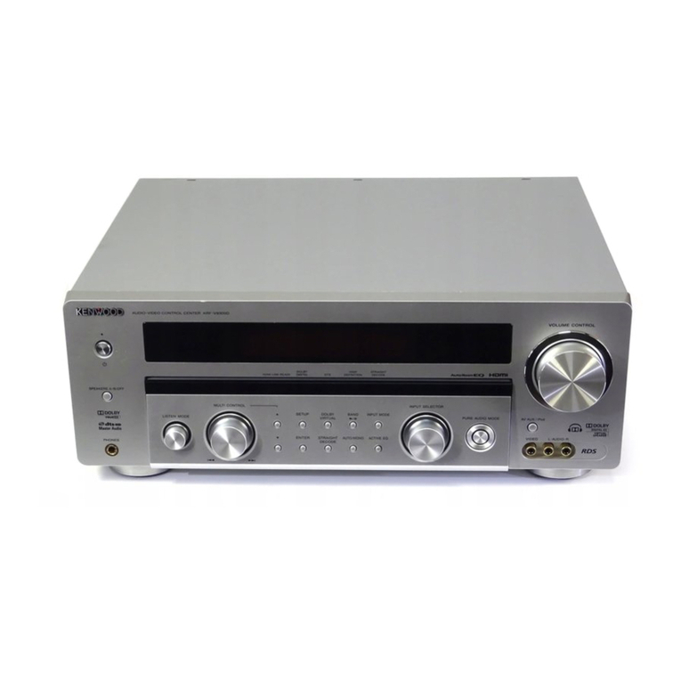
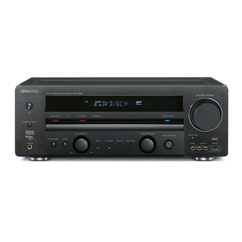
Kenwood RC-95 User manual

REMOTE
CONTROL
SYSTEM
RO-95
INSTRUCTION
MANUAL
87/65
431
86/1211109876543
KENWOOD
TRIO-KENWOOD
CORPORATION
©PRINTED
IN
JAPAN
B50-6307-00(K,P,U,M,UE,X\(T)
Rear
panel
safety
precautions
CAUTION
RISK
OF
ELECTRIC
SHOCK
DO
NOT
OPEN
CAUTION:
TO
REDUCE
THE
RISK
OF
ELECTRIC
SHOCK,
DO
NOT
REMOVE
COVER
(OR
BACK).
NO
USER-SERVICEABLE
PARTS
INSIDE.
REFER
SERVICING
TO
QUALIFIED
SERVICE
PERSONNEL.
The
lightning
flash
with
arrowhead
symbol,
within
an
equilateral
triangle,
is
intended
to
alert
the
user
to
the
presence
of
uninsulated
‘‘dangerous
voltage’’
within
the
product's
enclosure;
that
may
be
of
sufficient
magnitude
to
constitute
a
risk
of
electric
shock
to
persons.
The
exclamation
point
within
an
equilateral
triangle
is
intended
to
alert
the
user
to
the
presence
of
important
operating
and
maintenance
(servicing)
instructions
in
the
literature
accompanying
the
appliance.
Ahkee

For
your
records
Record
the
serial
number,
found
on
the
back
of
the
unit,
in
the
spaces
designated
on
the
warranty
card,
and
in
the
space
provided
below.
Refer
to
the
model
and
serial
numbers
whenever
you
call
upon
your
dealer
for
information
or
service
on
this
product.
Model!
Serial
number
Unpacking
Unpack
the
unit
carefully
and
make
sure
that
all
accessories
and
cables
are
put
aside
so
they
will
not
be
lost.
Examine
the
unit
for
any
possibility
of
shipping
damage.
If
your
unit
is
damaged
or
fails
to
operate,
notify
your
dealer
immediately.
If
your
unit
was
shipped
to
you
directly,
notify
the
shipping
company
without
delay.
Only
the
consignee
(the
person
or
company
receiving
the
unit)
can
file
a
claim
against
the
carrier
for
shipping
damage.
We
recommend
that
you
retain
the
original
carton
and
packing
materials
for
use
should
you
transport
or
ship
the
unit
in
the
future.
Be
careful
not
to
incline
the
RC-95
toward
you
with
the
remote
control
unit
stored
in.
The
remote
con-
trol
unit
may
drop
off
from
the
main
unit.
Before
applying
power
Important!
U.S.A.,
Canada,
U.K.,
and
Australia
Units.
shipped
to
the
U.S.A.
and
Canada
are
designed
for
operation
on
120
volts
AC
only.
Units
shipped
to
the
U.K.
and
Australia
are
designed
for
operation
on
240
volts
AC
only.
These
units
are
not
equipped
with
an
AC
voltage
selector
switch
and
the
discussion
of
such
a
switch
that
follows
should
be
disregarded.
All
other
countries
Units
shipped
to
countries
other
than
the
U.S.A.,
Canada,
U.K.,
and
Australia
are
equipped
with
an
AC
voltage
selector
switch
on
the
rear
panel.
Refer
to
the
following
paragraph
for
the
proper
setting
of
this
switch.
aes)
AC
voltage
selection
This
unit
operates
on
110
—
120
or
220
—
240
volts
AC.
The
AC
voltage
selector
switch
on
the
rear
panel
is
set
to
the
voltage
that
prevails
in
the
area
to
which
the
unit
is
shipped.
Before
connecting
the
power
cord
to
your
AC
outlet,
make
sure
that
the
setting
posi-
tion
of
this
switch
matches
your
line
voltage.
If
not,
it
must
be
set
to
your
voltage
in
accordance
with
the
following
direction.
Note:
Our
warranty
does
not
cover
damage
caused
by
excessive
line
voltage
due
to
improper
setting
of
the
AC
voltage
selector
switch.
2
RC-95
(kK)
AC
110-120V~<4
RAC
220-240V~
AC
110-120V~<4
AC
220-240V~
This
shows
switch
lever
locked
in
the
220
—
240
V~
posi-
tion.
This
shows
switch
lever
locked
in
the
110
—
120
V~
posi-
tion.
Move
switch
fever
to
match
your
line
voltage
with
a
small
screwdriver
or
other
pointed
tool.
AC
voltage
selector
switch
ee
|
For
United
Kingdom
The
mains
plug
must
be
removed
from
the
wall
socket
prior
to
any
internal
examination.
Important
The
wires
in
this
mains
lead
are
coloured
in
accordance
with
the
following
code:
BlUG:
dis
stevnds
didnot
teeeatn
desc
Neutral
BROWN
sch
biecdss
sedate
point
ah
beaeuecon
cays
Live
The
wires
in
this
mains
lead
must
be
connected
to
the
terminals
in
the
plug
as
follows:
Wire
colour
Plug
terminal
marking
BIWG
uisate
vax
aa
da
eiiecerasese
Mae
es
N
or
Black
BROWN
Gia
idncetssauwcteaacstanmeas
ge.
Bes
L
or
Red
OE
Brown
to
Live
Blue
to
L
Neutral
N
Plug
Notes:
1)
If
a
13-amp
plug
is
used,
this
must
be
fitted
with
a
5-amp
fuse.
2)
If
a
3-pin
plug
with
earthing
contact
is
used,
no
wire
must
be
connected
to
the
E
terminal.
Safety
precaution
for
AC
plug
(For
U.S.A.
anh.
|
Canada)
CAUTION:
TO
PREVENT
ELECTRIC
SHOCK
DO
NOT
USE
THIS
(POLARIZED)
PLUG
WITH
AN
EXTENSION
CORD,
RECEPTACLE
OR
OTHER
OUTLET
UNLESS
THE
BLADES
CAN
BE
FULLY
INSERTED
TO
PREVENT
BLADE
EXPOSURE.
WARNING:
TO
PREVENT
FIRE
OR
ELECTRIC
SHOCK,
DO
NOT
EXPOSE
THIS
AP-
PLIANCE
TO
RAIN
OR
MOISTURE.

Before
operation
Safety
precautions
Never
remove
the
case.
If
the
internal
parts
are
touched
accidentally,
a
serious
electric
shock
might
occur.
Never
touch
internal
parts.
lf
a
metal
object,
such
as
a
hair
pin
or
a
needle,
comes
into
contact
with
the
power
socket
on
the
rear
panel,
a
dangerous
electric
shock
may
result.
For
families
with
children,
never
permit
children
to
put
anything,
especially
metal,
inside
this
unit.
aie
SN
o>}
ies
2”
Do
not
connect
other
audio
equipment
with
a
power
consumption
larger
than
that
specified
to
the
AC
outlet
on
the
rear
panel.
Never
connect
other
electrical
ap-
pliances,
such
as
an
iron
or
toaster.
Never
connect
other
electrical
appliances.
Touching
the
power
plug
when
your
hands
are
wet
may
result
in
a
serious
electric
shock.
Ao”
C
Never
touch
with
wet
W
hands.
Never
pull,
bend
or
extend
the
power
cord.
This
could
damage
the
power
cord,
resulting
in
a
broken
cord
or
short-circuit.
Never
pull
or
stretch
“the
cord.
In
case
of
abnormal
smell
\f
an
abnormal
smell
or
smoke
is
detected,
immediately
turn
the
power
OFF
and
pull
out
the
power
cord.
Con-
tact
your
dealer
or
nearest
service
station.
Cleaning
Do
not
use
volatile
solvents
such
as
alcohol,
paint
thin-
ner,
gasoline,
benzine,
etc.
to
clean
the
cabinet.
Use
a
silicone
cloth
or
a
clean
dry
cloth.
Silicone
cloth
Thinner
Benzine
Installation
precautions
a)
Avoid
locations
subject
to
direct
sunlight.
b)
Avoid
high
or
low
temperature
extremes.
c)
Keep
the
unit
away
from
heat
radiating
sources.
d)
Choose
a
location
that
is
relatively
free
of
vibra
tion
or
excessive
dust.
e)
Make
sure
power
is
off
before
making
any
system
connections.
RCE
(K)
J

Notes
SS
2
¢
When
the
power
plug
is
connected
to
an
ac
Satiots
this
unit
enters
the
power
standby
mode
and
the
in-
_
dicator
lights.
At-that
time.
the
unit
can
be
operated
only
with
the
POWER
key
of
remote.
control
transmitter.
-
First,
enter
the
unit
to
the
power
on
mode
with
the
;
POWER
key
of
remote
control
‘transmitter,
and
ss
_
operate
with
the
other
keys.
_
cee
¢
When
the
volume
contro!
of
the
control
amplifier
~_{KC-105)
is
not
increased,
the
VOLUME
keys
of
the
3
remote
control
transmitter
does
not
function.
Set
the
volume
control
to.
’'5’’
to
‘7’,
then
operate
—
the
VOLUME
eye
<
of
the
remote
contra
transmit-
ter.
When
the
volume
contol
of
the
control
amplifier
(KC-105).
is
set
to
’'8’'
to
’"10’’,
sound
may
be
pe
distorted.
See
os
Installing
the
battery
on
the
remote
control
unit
1.
Remove
the
battery
compartment
cover.
2.
Insert
two
size
‘‘AA’’
(R6)
batteries
confirming
the
correct
polarity
and
close
the
cover
in
its
place.
Insert
the
remote.
control
unit
until
the
click
sound
is
heard.
4
RC-95
(k)
How
to
take
out
the
remote
control
unit
Push
once
and
release
your
finger,
the
remote
control
unit
is
slightly
popped
out,
then
pull
it
out
with
your
hand.
When
the
main
unit
is
moved
by
pushing
the
remote
control
unit,
stick
the
provided
high-grip
spacer
on
the
insulator.
Usable
range
of
remote
control
unit
The
usable
range
of
the
remote
control
unit
may
differ
on
temperature,
humidity
or
using
conditions,
however,
it
is
defined
approximately
as
shown
in
the
figure
below:

An
example
of
synchro
connection
Speaker
R
Turntable
(KD-75F/KD-65F)
Speaker
L
—E?
Synchro
cord
AM
outdoor
antenna
FM
indoor
antenna
300
Q
feeder
-————
FM
outdoor
@D
Cane
|
+
Power
amplifier
(KM-205/
KM-105)
=)
antenna
75
2
coaxial
cable
'
Remoto
control
(RC-95)
(DP-850)
Compact
disc
player
=|
==
AC
wal
Using
the
supplied
miniplug
cord,
connect
the
System
Control
terminal
on
the
rear
panel
of
the
RC-95
to
the
System
Control
terminal
on
the
rear
panel
of
the
KC-105
(Control
amplifier),
then
connect
each
audio
terminal
between
the
KC-105
(control
amplifier)
and
the
KM-105/205
(power
amplifier).
Connect
the
synchro
cord
securely.
outlet
AC
outlet
(Except
some
areas)
The
AC
outlet
on
the
rear
panel
can
be
used
to
wipply
power
to
other
component
in
the
system.
Normally,
connect
this
AC
outlet
as
shown
in
this
con-
nection
diagram.
UNSWITCHED
outlet:
The
outlet
provides
>»
ower
when
the
unit
is
plugged
into
an
active
AC
wall
>
utlet,
regardless
of
the
setting
of
the
POWER
switch.
The
maximum
capacity
is
800
watts.
RC
(K)
§

Controls
and
indicators
Remote
control
main
unit
front
panel
KENWOOD
_
remote
CONTROL
SYSTEM
RC-95
OPERATION
or
#POWER
STAND
BY
nf
FULL-FUNCTION
REMOTE
CONTROL
WITH
6
INPUT
SELECTION
EMOTE
SENSOR
VOLUME
UP/DOWN
SYSTEM
as:
POWER
ON/OFF
ANO
MUTING
Remote
control
unit
TAPE-2
TAPE-1
KENWOOD
REMOTE
CONTROL
UNIT
RC-95
Note
for
remote
control
operatio
After
pressing
one
of
operation
keys,
when
the
next
Operation
is
required,
press
the
next
operation
key
firmly
after
approx.
1
second
interval.
When
the
next
operation
key
is
pressed
immediate-
ly
after
the
previous
key,
it
may
cause
mis-
Operation.
6
&c-95
(Kk)
@
Remote
control
unit
storage
slot
Insert
the
remote
control
unit
(transmitter)
into
this
slot
when
not
in
use.
@
Operation
indicator
(OPERATION/POWER
STANDBY)
When
the
power
plug
is
connected
to
the
AC
outlet,
the
unit
enters
to
the
power
standby
mode
and
the
in-
dicator
lights.
This
indicator
blinks
when
a
key
on
the
remote
control
transmitter
is
pressed
and
its
infrared
signal
is
received
by
the
main
unit.
Note:
During
the
power
off
condition
with
its
AC
plug
con-
nected,
no
key
is
accepted
other
than
the
POWER
key.
@®
VOLUME
LEVEL
indicator
This
indicated
the
level
of
the
electronic
volume
on
the
main
unit.
When
the
MUTE
key
is
pressed,
the
volume
level
is
at-
tenuated
by
20 dB
and
the
LEVEL
indicator
blinks.
When
the
POWER
switch
is
set
to
ON
with
the
POWER
connected
first,
VOLUME
LEVEL
indicators
1
and
2
light.
The
volume
level
of
the
main
unit
has
been
set
to
—58
dB.
As
the
preset
sound
level
is
relatively
lov
to
protect
speakers,
increase
it
in
case
of
necessity
in
ac-
tual
operation.
The
volume
levels
indicated
by
the
LEVEL
indicata
are
as
follows.
When
LEDs
1
are
lit:
—76
to
—60
dB
When
LEDs
1
to
2
are
lit!
—58
to
—40
dB
When
LEDs
1
to
3
are
lit!
—38
to
—20
dB
When
LEDs
1
to
4
are
lit!
—18
to
O
dB
e
The
volume
is
maximum
at
0
dB.
As
shown
akove,
the
volume
is
not
always
maximum
even
when
LEDs
up
to
4
are
lit.
@
Infrared
remote
control
sensor
(REMOTE
SENSOR)
Operate
the
remote
control
unit
with
its
front
tov
ard
this
sensor
position.

@
Compact
disc
player
(DP-850)
operation
keys
(CD)
Play
key
(>)
When
this
key
is
pressed
with
a
compact
disc
loaded
in
the
compact
disc
player,
the
disc
is
played.
(Same
function
as
the
play
key
on
the
compact
disc
player.)
When
this
key
is
pressed
during
play,
the
player
enters
the
pause
mode.
To
release
pause
mode,
press
it
again.
Stop
key
(Mf)
Press
to
cancel
all
operations.
The
pickup
returns
to
the
beginning
of
the
first
tune
and
the
player
enters
the
standby
mode.
(Same
function
as
the
stop
key
on
the
compact
disc
player.)
Music
search
key
(>>)
Press
to
skip
to
the
beginning
of
the
next
tune.
The
pickup
is
advanced
to
the
forward
tunes
by
the
number
of
times
it
is
pressed.
(Same
function
as
the
music
search
key
on
the
compact
disc
player.)
Music
search
key
(4)
Press
to
return
to
the
beginning
of
the
current
tune.
Pressing
it
again
returns
the
pickup
to
the
beginning.
When
the
key
is
continuously
pressed,
the
pickup
returns
to
the
backward
tunes
by
the
number
of
times
it
is
pressed.
(Same
function
as
the
music
search
key
on
the
compact
disc
player.)
@
Tuner
(KT-75)
operation
keys
(TUNER)
Band
select
keys
(AM/FM)
Select
the
desired
band
for
broadcast
listening.
(Same
function
as
the
band
selector
on
the
tuner.)
Note:
The
LW
band
cannot
be
selected.
Preset
channel
(CH)
UP/DOWN
keys
(A/V)
Press
to
recall
the
preset
channel.
When
the
key
is
pressed
during
listening
to
the
preset
channel
station,
the
preset
channel
number
is
moved
up
or
down
to
receive
another
preset
channel.
For
example:
When
the
DOWN
key
When
the
UP
key
(¥)
is
pressed
(A)
is
pressed
—_——_—_—-
—
t
2
3
4
5
6
7
8
9
0
Currently
received
preset
channel
When
none
of
preset
channel
is
received,
pressing
UP
key
(A)
once
selects
the
preset
channel-1,
and
press-
ing
the
DOWN
key
(¥)
once
selects
the
preset
channel-0.
@
Cassette
deck
(KX-95W,
KX-75R)
opera-
tion
keys
(TAPE-1
A/TAPE-1
B)
Stop
key
(Mf)
Press
to
stop
tape
running.
Rewind
key
(
<<}
Press
to
fast-wind
the
tape
to
the
left
reel.
Fast-forward
key
(>>)
Press
to
fast-wind
the
tape
to
the
right
reel.
Reverse
Play
key
(<)
Press
to
start
playback
in
reverse
direction.
(Rear
side
playback)
Play
key
(>)
Press
to
start
playback
in
forward
direction.
(Front
side
playback}
Pause
key
(11)
Press
to
stop
play
back
or
recording
momentarily.
The
function
of
the
PAUSE
key
of
the
TAPE-1
A
is
the
same
as
that
of
STOP
key.
Record
key
(REC)
(@)
(TAPE-1
B
cassette
deck
of
KX-95W
or
KX-75R)
Press
to
start
recording.
(When
the
KX-75R
is
used,
it
cannot
be
operated
even
if
one
of
the
TAPE-1
A
opera-
tion
keys
is
pressed.)
@®
VOLUME
keys
(UP/DOWN)
Controls
the
volume
of
the
speakers
and
headphones.
Press
the
UP
(A)
key
to
increase
the
volume
level
and,
press
the
DOWN
(7)
key
to
decrease
it.
Note:
The
volume
is
raised
up
to
the
level
preset
at
the
control
amplifier.
INPUT
mode
switches
Amplifier
(KC-105)
operation
keys
(These
function
same
as
the
operation
keys
on
the
amplifier.)
TUNER
:
Press
to
listen
to
the
radio
broadcast.
cD
:
Press
to
listen
to
the
compact
discs.
PHONO
:
Press
to
listen
to
the
records.
AUX/VIDEO
:
Press
to
listen
to
the
program
source
from
the
equipment
connected
to
the
AUX
IN/VIDEO
terminals
on
the
rear
panel
of
the
amplifier.
TAPE-1
:
Press
to
listen
to
tapes
with
‘the
cassette
deck
connected
to
the
TAPE-1
terminals.
TAPE-2
:
Press
to
listen
to
tapes
with
the
cassette
deck
connected
to
the
TAPE-2
terminals.
MUTING
key
Press
to
decrease
the
volume
level
instantaneausly.
Pressing
it
again
resumes
the
previous
volume
level.
When
this
key
is
pressed,
volume
level
is
decreased
by
20
dB.
The
VOLUME
LEVEL
indicators
blink.
@
POWER
switch
Press
to
turn
the
power
on
for
whole
system.
Thisfunc-.
tions
same
as
the
POWER
switch
on
the
tuner
(KT-75).
@
Turntable
(KD-75F,
KD-65F)
operation
keys
(PHONO)
Play
key
(<)
Press
to
start
record
play
automatically.
For
KD-65F,
select
the
record
size
when
turning
the
power
on,
before
starting
play
with
this
key.
Stop
key
(HM)
Press
to
stop
play;
the
tonearm
returns
to
the
rest
and
the
platter
stops
rotating.
@
Battery
check
indicator
(CHECK)
This
indicator
lights
when
one
of
operation
keys
is
pressed.
When
it
is
not
lit,
batteries
are
exhassted,
Replace
them
with
new
batteries.
RCW
(K)
7

In
case
of
difficulty
What
may
seems
to
be
a
serious
malfunction
is
not
always
so.
Before
calling
for
service,
check
the
following
accor-
ding
to
the
symptom.
Symptom
Cause
Remedy
Remote
control
unit
does
not
function.”
.
Batteries
are
exhausted.
.
Stereo
mini
plug
cord
is
discon-
nected
from
the
rear
panel
terminal.
Note:
———_—_______-
When
the
RCA
pin
cords
are
not
connected
to
this
controller,
remote
controller
does
not
function.
.
Operating
position
is
too
distant
from
the
main
unit
(infrared
sensor).
.
Record,
tape
or
compact
disc
is
not
loaded
on
the
component
desired
to
be
played.
.
Cassette
deck
desired
to
play
is
in
use
for
recording.
.
Use
the
Volume
level
is
not
increased.
.
Volume
exceeds
the
level
set
at
the
control
amplifier.
.
Muting
is
activated.
.
Replace
the
batteries
with
new
ones.
.
Connect
it
firmly.
remote
control
unit
(transmitter)
within
an
operable
area.
.
Set
the
desired
source
on
the
component.
.
Wait
until
the
recording
is
over.
.
Raise
the
level
on
the
control
amplifier.
.
Release
it.
Specifications
Audio
Input
sensitivity/Impedance
........................
150
mV/100
kQ
Gales
etviacdtavis
Rhee
Late
ein
ie
Ae
O dB
(VR.
MAX.)
Output
level/Impedance
.............................
150
mV/1
kQ
Remote
control
Maximum
remote-controllable
distance
.........
6
m
(on
an
axis
of
optical
sensor)
Remote
control
system
.......................:008
Infrared
control
system
Power
requirements
for
remote
control
TIANSMICCOl
soe
ee
cscadecceeehsss
ha
eh
eae
DC3V
Power
consumption
................0......0:0eee
eee
3
W
AC
outlet.
6.e
atin
Sein
encciestiecanmeieteies
UNSWITCHED
x
1
(Except
some
area)
Dimensions
..................0..0.0cce
ccc
eeeeeeeen
ee
eees
420
(W)
x
59
(H)
x
223
(D)
mm
"
(16—-9/16""x2-—5/16"
x
8-3/4")
Weight
(Net)
............0.....0.0:
cece
cece
eee
es
1.5
kg
(3.3
Ib)
ACCESSOPIOS
iss
s.sichicsies
del
oa
losin
oiesteces
aan
Synchro
cord
Remote
control
transmitter
unit
Size
‘‘AA"’
(R6)
battery
x
2
Note:
We
follow
a
policy
of
continuous
advancements
in
development.
For
this
reason
specifications
may
be
changed
vith-
out
notice.
Table of contents
Other Kenwood Control System manuals