Zeva BMS16 User manual

Zero emission
Vehicles AustrAliA
http://www.zeva.com.au
BMS16
Battery Management System
For 12-16 cell lithium battery packs
v1.2
Introduction
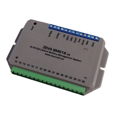
The ZEVA BMS16 is an integrated battery management system for lithium battery packs
containing 12-16 cells in series and 10-1000 Ah capacity. It is suitable for both electric
vehicle and battery storage applications. The BMS16 includes an internal power supply to
allow it to run directly from the battery pack, internal shunt resistors for automatic pack
balancing, dual solid state relay outputs for directly switching power contactors to protect
charging and discharging of batteries, and a CAN bus port for optional colour touchscreen
interface or integration with third party control systems.
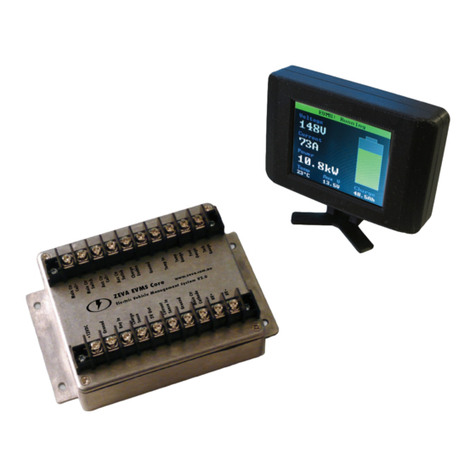
The BMS16 Monitor provides information such as voltage, current, power, battery state of
charge, and all individual cell voltages. It can also be used for conguring the operating
parameters of the BMS16. It may be installed up to 50m from the BMS16 (if correct shielded
twisted pair cable is used).
Battery management systems are the last line of defence for your battery pack. In normal
circumstances it should not interfere with the battery pack’s operation, only intervening
when something goes wrong and protection is required.
Safety Warning
Although 16-cell lithium battery packs do not involve lethal voltages, they frequently involve
dangerous amounts of current and power. Proper precautions and electrical safety procedures
should always be observed. Please read this manual carefully to ensure correct installation
and operation. If you are unsure of anything, please contact us before proceeding.
We have endeavoured to make a safe and reliable product which performs as described,
however since ZEVA has no control over the integration of its products into a battery system,
we can assume no responsibility for the nal safety or functionality of the completed
installation. It is up to the end user to determine the suitability of the products for the purpose
employed, and the end user assumes all risks associated. Products should only be installed
by suitably qualied and experienced persons, and should always be used in a safe and
lawful manner.
Specications
Number of cells: 12-16•
Battery types: LiFePO4, LiCo, LiMn, etc•
Accuracy: Within 0.01V per cell•
Battery capacity: 10-1000Ah•
Current measurement: 0-1000A (depending on shunt used)•
Dimensions: 170x90x20mm•
Outputs: Dual solid state relays, 60V 1.3A max, internally fused•

Installation
The BMS16 should be mounted securely using screws through the holes on the case anges.
Install the BMS16 in a location protected from direct sun and water and close to the cells if
possible to minimise cell wiring lengths (under 1m recommended).
The BMS16 has a pluggable screw terminal block for the (up to) 17 cell connections, with
the most point of the battery pack connected to the terminal near C00, and successive
positive terminals connected to C01-C16. Wire gauge around AWG20-26 is recommended
for sufcient mechanical strength and suitable current rating. We recommend wiring up the
plug and verifying all voltages before connecting to the BMS. The plug requires a signicant
amount of force to fully engage; ensure it is plugged all the way in for reliable connections.
If you need to disconnect the cell plug from the BMS, signicant force is required for removal
as well. For easier removal, a at blade screwdriver may be used to lever the positive end of
the plug out rst, which should then be loose enough to remove by hand.
Ensure that all wiring is secured so it will not become damaged from vibration or abrasion.
Optionally small fuses (~1A) may be used to protect wiring, best installed close to each cell
terminal. Power is always taken from the most positive input C16. If using the module with
fewer than 16 cells, simply add a short jumper wire from your most positive cell terminal to
C16. An example wiring diagram for 16 cells is shown below:
Relay outputs are oating / isolated, and have a maximum rating of 60V and 1.3A continuous.
Be sure to include a yback diode (if not built in to the relay/contactor) to suppress inductive
voltage spikes from switching the relay coil. In installations with a single “battery enable”
relay, the LV and HV relays may be wired in series such that either an over-voltage or under-
voltage condition will open the relay to isolate the battery pack.
Once your wiring is complete, use a small screwdriver to press the power button on the
top left of the case, and the status LED should come on. A green light indicates all cells are
within correct voltage range, and both relay outputs will be closed circuit. A steady red light
indicates one or more cells are over-voltage, and the HV Relay outputs will be open circuit.
A blinking red light indicates one or more cells are under-voltage, and the LV Relay outputs
will be open circuit. Green/red ashing indicates an over-temperature shutdown.
Current Shunt
The BMS16 may be supplied with either a 100A, 200A or 500A rated shunt. These are
continuous current ratings, but the BMS can measure up to twice the rated current
intermittently. Note that the current shunt may get very hot with sustained current above
its continuous rating. The shunt is connected via two wires to the shunt terminals on the
BMS16. For best performance, twisted pair wire is recommended. The sample wire from the
anode / positive side of the shunt (closest to the +ve of the battery) should be connected to
the terminal nearest the edge of the BMS. When used with a monitor, the current displayed
is discharge amps – i.e charge amps will be negative values. If your polarity seems to be
reversed, simply swap the two shunt wires into the BMS.
Temperature Sensing
The BMS16 is supplied with a 10Kohm NTC thermistor for temperature sensing. It is
connected to the two Temp screw terminals at the rear of the case, and is non-polarised.
It is recommended that the temperature sensor be installed somewhere near the middle of
the pack, since this is typically the warmest location (wires on the sensor may be extended
as long as necessary). The default temperature limit of 80˚C suits most lithium battery types.
CAN Bus Wiring
There are four screw terminals for connecting the BMS16 to a CAN bus, and a Molex C-Grid
SL plug on the optional BMS Monitor, with the following pin identications:
CAN pin assignments on BMS16 housing
Shield
CAN L
CAN H Gnd
12V
CAN pin assignments on Monitor housing

The 12V terminal is an output for optionally providing power to external devices, such as a
monitor (200mA max, fuse protected). The CAN bus is galvanically isolated from the battery
pack so can be safely connected to external ground references.
CAN busses work best when wired as a single daisy chain of devices, with 120Ω termination
resistors at each end to prevent signal reection. At least one termination resistor is required
for the CAN bus (and BMS16) to function. The BMS16 comes with a termination resistor
which may be omitted if the device is not at one end of the CAN bus. (For short CAN busses,
often one termination resistor – such as the one built in to the BMS Monitor – is sufcient.)
For best performance, shielded twisted pair (STP) cable is recommended. Very short
connections are usually OK with untwisted and/or unshielded cable.
BMS16 Monitor
The BMS16 Monitor is an optional colour touchscreen which may be used to remotely
interact with the BMS16. The Monitor displays various pages of information:
ZEVA BMS: Running
Voltage
Current
Power
Temp SoC
23˚C 90%
48.5V
12.3A
0.6kW
The standard display when the system is running,
showing pack voltage, current, power, temperature,
battery state of charge.
Touching the panel briey will toggle between this
and the voltages page below.
ZEVA BMS: Voltages
3.32V 3.33V 3.32V 3.31V
3.33V 3.31V 3.32V 3.32V
3.31V 3.32V 3.33V 3.32V
3.32V 3.32V 3.33V 3.31V
This page shows all individual cell voltages, plus a bar
graph below. Dotted lines on the graph show HV and
LV thresholds plus hysteresis.
Graph bars will be green when a cell is in range, blue
for under-voltage, red for over-voltage, and orange if a
cell is currently being shunt balanced.
Warning:
Overcurrent shutdown
If the BMS detects an error, this warning page
will be displayed. In most cases, the error can be
acknowledged/reset by tapping the screen.
Reset SoC
Enter Setup
Display Off
Power Off
Exit Options
You can bring up the options menu by touching and
holding for 1 second. From here you can do a manual
reset of the State of Charge (back to 100%), enter the
Setup mode, switch the display off, or command the
BMS16 to turn off. (When the display is off, touch and
hold anywhere for 1 second to turn it back on. Display
will automatically wake if there is a new warning to
display.)
ZEVA BMS: Setup
Parameter:
Pack capacity
Value:
100Ah
Exit Setup
<
<
>
>
If you choose Enter Setup, the Monitor can be used
to recongure settings for the BMS16. The top row
selects the parameter, and the bottom row adjusts the
value, in both cases by touching the left or right arrows
on each side. Once nished, touch Exit Setup and the
new parameters will be transmitted to the BMS16.
List of Settings
The following table describes the parameters available in the Settings page.
Name Range Description
Number of cells 12-16 The number of cells the BMS16 expects to see
connected.
Pack capacity 10-1000Ah The rated capacity of your traction battery pack,
in Amp-Hours.
SoC warning 0-100% The BMS16 can raise a warning when the
traction battery’s SoC reaches a predetermined
level. (Use 0% to disable.)
Full voltage 1-100V The BMS uses a “full voltage” threshold
(combined with low charge current) to detect
charge completion and automatically re-
synchronize the SoC to 100% when pack
voltage is within 1V of this value. Typically set
value to your peak charge voltage.
Warn current 0-1000A The BMS16 will provide a warning if the current
in or out of the battery exceeds this threshold.
Set to 0A to disable (will display as “off”).

Trip current 0-1000A The BMS16 will automatically shut down the
battery pack if current exceeds this threshold
(for over 1 second continuously). Note: This
should not replace a physical fuse, but can be
used as a “rst line of defence”.
This is considered a serious error which will
require the device to be power cycled to reset.
Thermal limit 0-100C The BMS can automatically shut down the
battery pack (both charge and load output
relays) if the measured temperature exceeds
this programmed threshold. This error will
automatically reset once temperature drops by
at least 10 degrees below threshold.
Min voltage 1.00-5.00V The minimum voltage any single cell should
be allowed to reach. If any cell goes below this
threshold (minus any hysteresis), the LV output
relay will go open circuit.
Max voltage 1.00-5.00V The maximum voltage any single cell should
be allowed to reach. If any cell goes above this
threshold (plus hysteresis), the HV output relay
will go open circuit.
BMS hysteresis 0-1.00V This settings provides some hysteresis on
voltage thresholds, such that charge and load
relays are not switched on and off too rapidly.
For example, with a 0.2V hysteresis, the LV relay
will be disabled when a cell goes 0.2V below
the Min Voltage threshold, and re-enabled once
the cell recovers to 0.2V above Min Voltage.
Shunt voltage 1.00-5.00V The voltage threshold where shunt balancing will
occur. Balancing should only be performed on
cells which are higher than average, so typically
set this to the average maximum charge voltage
of each cell (i.e max charge voltage divided by
number of cells).
Shunt size 100A / 200A /
500A
This selects the size of current shunt attached to
the BMS16 (for 75mV shunts). Note that if using
an external CAN bus shunt interface, this setting
is ignored as the external device is separately
programmed with its shunt size.
BMS Power Consumption Protection
An inherent problem with any BMS which powers itself from the cells it is monitoring is that
the BMS can slowly discharge the cells, which can eventually atten cells – particularly if
powering contactors or monitors, and no charging source is present for an extended period.
To prevent possible damage, the BMS16 is able to switch of its own power supply if any cells
get critically low (under 2.0V). If your BMS has turned off due to a critically low cell, simply
attach a charging source to the batteries then press the power button to re-enable the BMS.
Tech Support and Warranty Information
All ZEVA products are covered by a 12 month warranty against manufacturing faults or
failures under normal operating conditions. The warranty does not cover misuse of the
product, including but not limited to: excessive voltage or reversed polarity on terminals,
short circuits on outputs, opening of housings and/or modication of internal electronics,
severe impact damage, submersion in water.
We have taken great care to design a safe and reliable product, but faults can happen. If
you believe your product has a fault, please contact us via our website to discuss. If it is
determined that a hardware fault is the likely cause, we will provide an RMA number and
return address to proceed with repairs.
If you have any questions not covered by this manual, please contact us via our website:
http://www.zeva.com.au
Other Zeva Control System manuals
Popular Control System manuals by other brands

Astral Pool
Astral Pool LumiPlus WiFi Acces Point Installation and maintenance manual

Signature Control Systems
Signature Control Systems EZ Indoor 8124US Installation and programming guide

HIK VISION
HIK VISION DS-K260X-G Quick setup guide

Aqua Control
Aqua Control C4115 manual

BM PRO
BM PRO OdysseyControl owner's manual

Ansul
Ansul AUTOPULSE 442R Inspection, Operation, and Maintenance Manual