Kenwood KHG 601 User manual

BUILT-IN
COOKING HOBS
models KHG 601, KHG 602
Instructions for use - Installation advice
Before operating this hob,
please read these instructions carefully
GB
IE

2
DECLARATION OF CE CONFORMITY
This cooking hob has been designed to be used only for cooking. Any other use (such–
as heating a room) is improper and dangerous.
This cooking hob has been designed, constructed, and marketed in compliance with:–
Safety requirements of EU “Gas” Directive 2009/142/EC;
•
Safety requirements of the “Low voltage” Directive 2006/95/EC;•
Safety requirements of the “EMC” Directive 2004/108/EC;•
Requirements of EU Directive 93/68/EEC.•
GB
IE
CONTENTS Page Number
Introduction . . . . . . . . . . . . . . . . . . . . . . . . . . . . . . . . . . . . . . . . . . . . .
Before Using for the First Time . . . . . . . . . . . . . . . . . . . . . . . . . . . . . .
Important Safeguards & Recommendations . . . . . . . . . . . . . . . . . . . .
Features . . . . . . . . . . . . . . . . . . . . . . . . . . . . . . . . . . . . . . . . . . . . . . . .
How to Use the Cooktop . . . . . . . . . . . . . . . . . . . . . . . . . . . . . . . . . . .
Cleaning & Maintenance . . . . . . . . . . . . . . . . . . . . . . . . . . . . . . . . . . .
Advice for the Installer . . . . . . . . . . . . . . . . . . . . . . . . . . . . . . . . . . . . .
Installation . . . . . . . . . . . . . . . . . . . . . . . . . . . . . . . . . . . . . . . . . . . . . .
Gas Section . . . . . . . . . . . . . . . . . . . . . . . . . . . . . . . . . . . . . . . . . . . . .
Electrical Section . . . . . . . . . . . . . . . . . . . . . . . . . . . . . . . . . . . . . . . . .
Guarantee & After Sales Service . . . . . . . . . . . . . . . . . . . . . . . . . . . . .
3
4
4
5
6 - 8
9 - 11
12
13 - 15
16 - 20
21 - 22
23

3
Dear Customer,
Thank you for purchasing a Kenwood Gas Hob.
The safety precautions and recommendations in these instruc-
tions are for your own safety and that of others.
They will also provide a means by which to make full use of
the features offered by your appliance.
Please keep this booklet in a safe place. It may be useful
in future, either to yourself or to others in the event that doubts
should arise relating to its operation.
This appliance must be used only for its intended purpo-
se, that is for the domestic cooking of foodstuffs.
Any other form of usage is to be considered as inappropria-
te and therefore dangerous.
The manufacturer declines all responsibility in the event
of damage caused by improper or incorrect use of the ap-
pliance.
For European Union countries only:
These instructions are only valid for the countries indicated by the symbols on the
cover of the instruction booklet and on the appliance itself.

4
BEFORE USING FOR THE FIRST TIME
Read the instructions carefully before installing and using the appliance.•
After unpacking the appliance, make sure it is not damaged. In case of doubt, do not•
usetheapplianceandcontactyoursupplieroraqualiedengineer.
Remove all packaging and do not leave the packing material (plastic bags, polyst-•
yrene, bands etc ) in easy reach of children as they may cause serious injury. The
packaging materials are recyclable.
The appliance should be installed and all the gas/electrical connections made by a•
qualiedengineerincompliancewithlocalregulationsinforceandfollowingthema-
nufacturer’s instructions.
Do not attempt to modify the technical properties of the appliance, as it may become•
dangerous to use.
IMPORTANT SAFEGUARDS & RECOMMENDATIONS
Donotcarryoutanycleaningormaintenancewithoutrstdisconnectingtheappliance•
from the electrical supply.
During and after use of the hob, certain parts will become very hot. Do not touch hot•
parts.
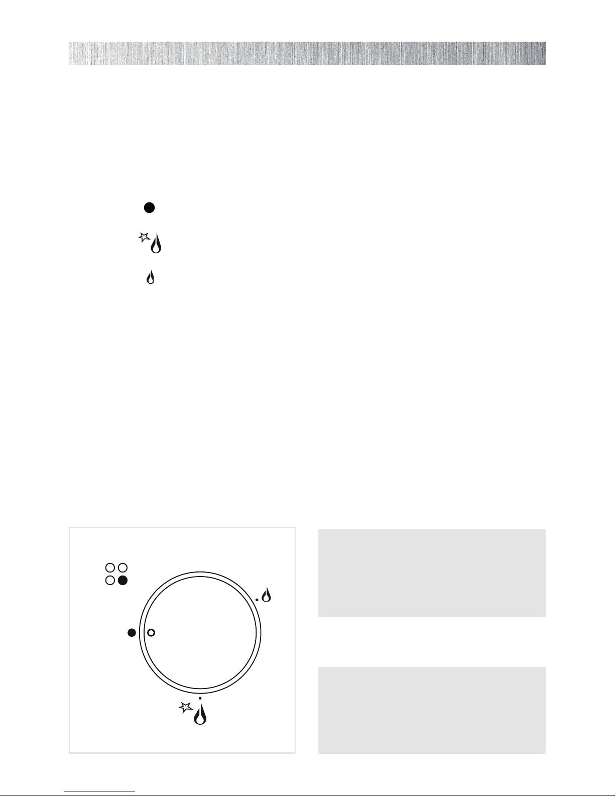
After use always ensure that the control knobs are in the “• ” OFF position.
Keep children away from the hob during use.•
Household appliances are not intended to be played with by children.•
Children, or persons with a disability which limits their ability to use the appliance,•
should have a responsible person to instruct them in its use. The instructor should
be satised that they can use the appliance without danger to themselves or their
surroundings.
WARNING•
When correctly installed, your product meets all safety requirements laid down for this
type of product category. However special care should be taken around the underne-
ath of the appliance as this area is not designed or intended to be touched and may
contain sharp or rough edges, that may cause injury.
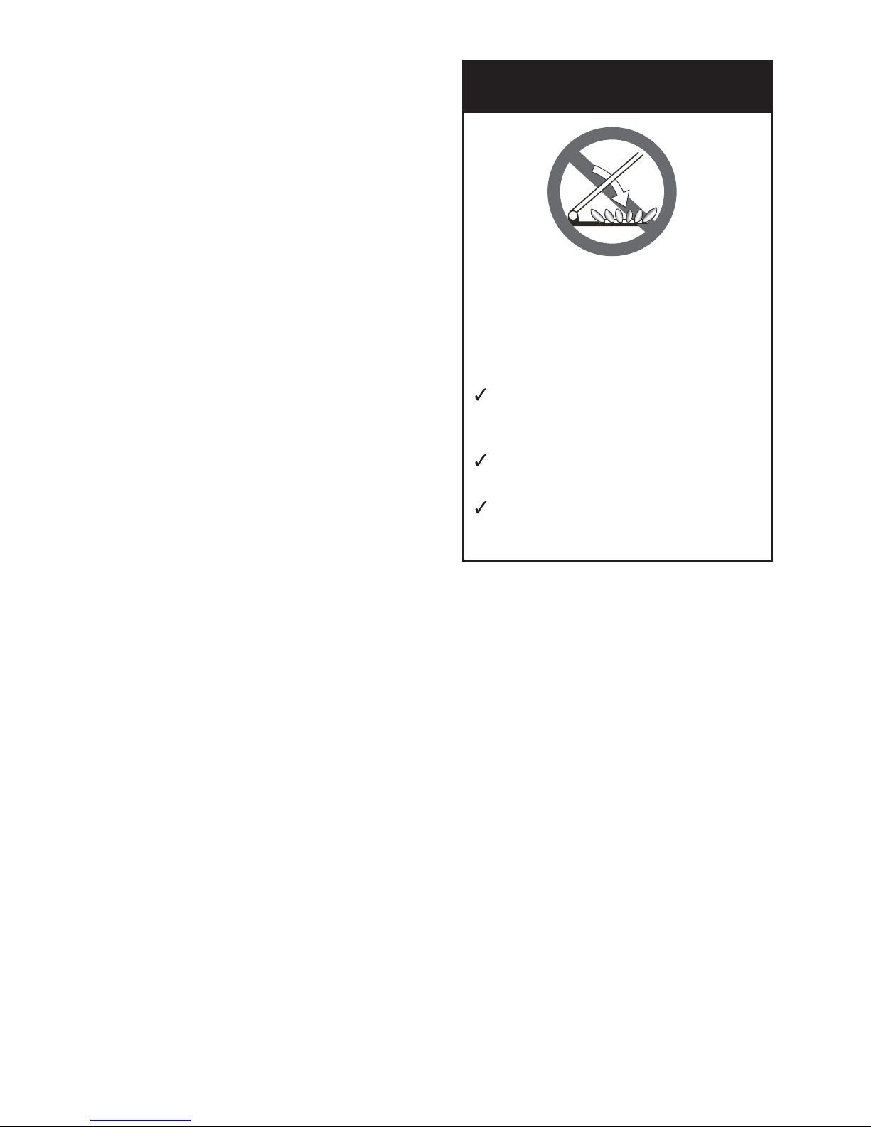
Fire Risk!• DonotleaveinammablematerialsontheHobtop.
Make sure that electrical cords connecting other appliances in the proximity cannot•
come in to contact with the Hob top.
Never use a damaged appliance. Get it checked or repaired: “see after-sales servi-•
ce”.
CAUTION: If the burner is accidentally extinguished, turn the gas off by the control•
knob and wait for at least 1 minute before attempting to relight.
CAUTION: this appliance must only be installed in a permanently well ventilated room•
in compliance with the applicable regulations.
When the appliance is not being used, it is advisable to keep the gas tap closed.•
Regularlubricationofthegastapsmustonlybecarriedoutbyqualiedengineers.•
Contact Service in case of problems with the operation of the gas taps.
Before disposing of an unwanted appliance, it is recommended that it is made inope-•
rative and that all potentially hazardous parts are made harmless.
Important: This appliance has been designed for domestic use only. The appliance•
is NOT suitable for use within a semi-commercial, commercial or communal environ-
ment.
If the supply cord is damaged, it must be replaced by a special cord by a quali-•
ed electrical technician in order to avoid a hazard.

5
GAS BURNERS
Auxiliary burner (A) 1,00 kW1.
Semirapid burner (SR) 1,75 kW2.
Rapid burner (R) 3,00 kW3.
Triple ring burner (TC) 3,50 kW4.
CONTROL PANEL DESCRIPTION
Auxiliary burner control knob (1)5.
Rapid burner control knob (3)6.
Left semirapid burner control knob (2)7.
Right semirapid burner control knob (2)8.
Triple ring burner control knob (4)9.
NOTE:
The electric ignition is incorporated in the knobs.•
Themodelhasasafetyvalvesystemtted,theowofgaswillbestoppedifandwhen•
theameshouldaccidentallygoout.
CAUTION:
If the burner is accidentally extinguished, turn the gas off at the control knob and wait at
least 1 minute before attempting to relight.
CAUTION:
Gas hobs produce heat and humidity in the environment in which they are installed.
Ensure that the cooking area is well ventilated by opening the natural ventilation grilles or
by installing an extractor hood connected to an outlet duct.
CAUTION:
If the hob is used for a prolonged time it may be necessary to provide further ventilation by
openingawindoworbyincreasingthesuctionpoweroftheextractorhood(iftted).
Fig. 1.2Fig. 1.1
1 - FEATURES
8
1
22
3
5
6
7
1
22
4
8
5
9
7
Mod: KHG 601
This appliance is Class 3 This appliance is Class 3
Mod: KHG 602

6
GAS BURNERS
Gasowtotheburnersisadjustedbytur-
ningtheknobs(illustratedings.2.1)which
control the valves.
Turning the knob so that the indicator points
to the symbols printed on the panel achie-
ves the following functions:
– full circle
closed valve
– symbol maximum
apertureorow
– symbol minimum
apertureorow
N.B. When the cooktop is not being
used, set the gas knobs to their closed
positions and also close the cock val-
ve on the gas bottle or the main gas
supply line.
Fig. 2.1
To reduce the gas ow to minimum,
•
rotate the knob further anti-clockwise
to point the indicator towards the small
amesymbol.
The maximum aperture position per-
•
mits rapid boiling of liquids, whereas
the minimum aperture position allows
slower warming of food or maintaining
boiling conditions of liquids.
Other intermediate operating
•
adjustments can be achieved by posi-
tioning the indicator between the maxi-
mum and minimum aperture positions,
and never between the maximum
aperture and closed positions.
2 - HOW TO USE THE COOKTOP
Caution!
The cooking hob becomes very hot
during operation.
Keep children well out of reach.

7
CHOICE OF BURNER
The symbols printed on the panel beside
the gas knobs indicate the correspondence
between the knob and the burner.
The most suitable burner is to be chosen
according to the diameter and volume ca-
pacity of the container to be warmed.
It is important that the diameter of the pots
or pans suitably match the heating poten-
tial of the burners in order not to jeopardise
theefciencyoftheburners,bringingabout
a waste of gas fuel. A small diameter pot or
pan placed on a large burner does not ne-
cessarily mean that boiling conditions are
reached quicker.
DIAMETERS OF PANS WHICH
MAY BE USED ON THE HOBS
BURNERS MINIMUM MAX.
Auxiliary (1) 12 cm 14 cm
Semirapid 16 cm 24 cm
Rapid
24 cm 26 cm
Triple-ring 26 cm 28 cm
Wok (2) Max 36 cm
do not use pans with concave or con-
vex bases
(1) with grill for small cookware: minimum
diameter 6 cm (only for model KHG 601)
(2) only for model KHG 602
LIGHTING GAS BURNERS FITTED
WITH SAFETY VALVE DEVICE
In order to light the burner, you must:
Turn the knob in an anti-clockwise di-1.
rection up to the maximum aperture,
push in and hold the knob; this will
light the gas.
If there is no mains electrical supply,
bring a lighted match close to the bur-
ner.
Wait about ten seconds after the ga-2.
slights before releasing the knob (star-
ting time for the valve).
Adjust the gas valve to the desired po-3.
sition.
Iftheburnerameshouldgooutforsome
reason, the safety valve will automatically
stopthegasow.
To re-light the burner, return the knob to the
closed “ ” position, wait for at least 1
minute and then repeat the lighting proce-
dure.
N.B.: If your local gas supply makes it dif-
cult to light the burner with the knob set
to maximum, set the knob to minimum and
repeat the operation.
Fig. 2.3
Fig. 2.2

8
AUXILIARY GRATE FOR SMALL
PANS - Only for the model KHG 601
(g. 2.4)
This grate is to be placed on top of the
(smaller) auxiliary burner when using small
diameter pans, in order to prevent them
from tipping over.
Fig. 2.4
WOK STAND - Only for the model KHG 602 (gs. 2.5a, 2.5b)
This wok stand should be placed over the pan-rest for the triple ring burner.
Warning:
Using a wok without the stand may cause the burner to operate incorrectly.•
Donotusethestandforordinary,at-bottomedsaucepans.•
IMPORTANT:
The wok stand MUST BE PLACED ONLY over the pan-rest for the triple-ring burner.
WRONG CORRECT
Fig. 2.5b
Fig. 2.5a

9
Attention
The appliance gets very hot, mainly around the cooking areas. It is very important
that children are not left alone in the kitchen when you are cooking.
Do not use a steam cleaner because the moisture can get into the appliance thus
make it unsafe.
GENERAL ADVICE
Before you begin cleaning you must ensure that the hob is switched off.•
It is advisable to clean when the appliance is cold and especially when cleaning the•
enamelled parts.
All enamelled surfaces have to be washed with soapy water or some other non-abra-•
sive product with a sponge and are to be dried preferably with a soft cloth.
Avoid leaving alkaline or acid substances (lemon juice, vinegar etc.) on the surfaces.•
Do not use cleaning products with a chlorine or acidic base.•
WARNING
When correctly installed, your product meets all safety requirements laid down for
this type of product category. However special care should be taken around the un-
derneath of the appliance as this area is not designed or intended to be touched and
may contain sharp or rough edges, that may cause injury.
ENAMELLED PARTS
All the enamelled parts must be cleaned with a sponge and soapy water only or other•
non-abrasive products.
Drypreferablywithamicrobreorsoftcloth.•
If acid substances such as lemon juice, tomato conserve, vinegar etc. are left on the
enamel for a long time they will etch it, making it opaque.
STAINLESS STEEL ELEMENTS
Stainless steel parts must be rinsed with water and dried with a soft and clean cloth.•
Forpersistentdirt,usespecicnon-abrasiveproductsavailablecommerciallyoralittle•
hot vinegar.
Note: regular use could cause discolouring around the burners, because of the•
high ame temperature.
3 - CLEANING AND MAINTENANCE

10
CONTROL KNOBS
The control knobs may be removed for•
cleaning but care should be taken not to
damage the seal.
GAS TAPS
Periodic lubrication of the gas taps must•
be carried out by specialist personnel
only.
In the event of operating faults in the gas•
taps, call the Service Department.
BURNERS AND GRIDS
These parts can be removed and cleaned•
with appropriate products.
Aftercleaning, theburners andtheir a-•
me spreaders must be well dried and cor-
rectly replaced.
It is very important to check that the bur-•
ner ame spreader and the cap have
been correctly positioned.
Failure to do so can cause serious pro-•
blems.
Check that the electrode “• S” (gs. 3.1 -
3.3) is always clean to ensure trouble-free sparking.
Check that the probe “• T”(gs.3.1-3.3)nexttoeachburnerisalwayscleantoensure
the correct operation of the safety valves.
Note: To avoid damage to the electric ignition do not use it when the burners are not
in place.
Both the probe and ignition plug must be very carefully cleaned.
CORRECT REPLACEMENT OF THE AUXILIARY, SEMIRAPID AND RAPID
BURNERS
Itisveryimportanttocheckthattheburneramespreader“F” and the cap “C” have been
correctlypositioned(seegs.3.1and3.2).
Failure to do so can cause serious problems.
CORRECT POSITION OF TRIPLE RING BURNER
Thetripleringburnermustbecorrectlypositioned(seeg.3.3);theburnerribmustbe
ttedintheirhousingasshownbythearrow.
Theburnercorrectlypositionedmustnotrotate(g.3.4).
Then position the cap Aand the ring B(gs.3.4-3.5).
Do not shut lid when
burners alight
ATTENTION
Do not lower the glass lid when
burners are still hot or when the
oven is working or still hot.
Do not lay on the glass lid hot pans
and heavy kitchen utensils.
Dry off any liquid which may have
spilt on the cover before opening it.
GLASS LID
(Optional)

11
S
F
C
T
Fig. 3.1 Fig. 3.2
A
B
S
T
Fig. 3.3
Fig. 3.5Fig. 3.4

12
IMPORTANT
The appliance should be installed, regulated and adapted to function by a• QUALIFIED
INSTALLATION TECHNICIAN.
Failure to comply with this condition will render the guarantee invalid.•
The appliance must be installed in compliance with the regulations in force in your•
country and in observation of the manufacturer’s instructions.
Installation technicians must comply to current laws in force concerning ventilation and•
the evacuation of exhaust gases.
Always disconnect the appliance from the electrical supply before carrying out any•
maintenance operations or repairs.
The appliance must be housed in heat-resistant units.•
These tops are designed to be embedded into kitchen xtures measuring 600 •
mm in depth.
The walls of the units must not be higher than work top and must be capable of•
resisting temperatures of 105 °C above room temperature.
Do not install the appliance near inammable materials (eg. curtains).•
WARNING
When correctly installed, your product meets all safety requirements laid down for
this type of product category.
However special care should be taken around the underneath of the appliance as
this area is not designed or intended to be touched and may contain sharp or rough
edges, that may cause injury.
Advice for
the installer

13
TECHNICAL INFORMATION FOR THE
INSTALLER
In order to install the cooker top into the kitchen
xture,aholewiththedimensionsshowning.
4.2 has to be made, bearing in mind the fol-
lowing:
within the unit, between the bottom of the
•
cooktop and the upper surface of a shelf
there must be a clearance of at least 30
mm. It is absolutely essential that you pla-
ce a separator between the base of the
cooktop and the built-in unit or the oven;
the cooker top must be kept no less than•
200 mm away from any side wall (g.
4.2);
the hob must be installed at least 60 mm•
from the wall;
there must be a distance of at least 650•
mm between the hob and any wall cupbo-
ard or extractor hood positioned immedia-
telyabove(seeg.4.1);
if the hob is instal-•
led over a built-in
oven, there must
be a distance of
at least 30 mm
between the two
appliances. The
two appliances
shall be connec-
ted to the gas /
electrical supply
with independent
connections.
650 mm
60 mm min
200 mm min
500 mm
450 mm
580
480
500
60
0
–2
560
200
0
–2
Fig. 4.2
Fig. 4.1
4 - INSTALLATION
30 mm
Space for
connections
Clearance
Door
INSTALLATION IN KITCHEN
CABINET WITH DOOR(g.4.3)
It is recommended that a 30 mm clearance
beleftbetweenthecookertopandthex-
turesurface(g.4.3).
Fig. 4.3

14
FASTENING THE INSTALLATION BRACKETS (gs.4.4,4.5,4.6)
Each cooker top is provided with an installation kit including brackets and screws for•
fasteningthetoptoxturepanelsfrom2to4cmthick.
Turn the cooker top upside down and fasten the brackets “• Fand R” to the appropriate
socket holes, without tightening the screws “B” for the moment.
Makesurethatthebracketsarefastenedasshowninthegures.•
FASTENING THE COOKER TOP (gs.4.4,4.5,4.6)
Spread the sealing material “• D”outalongthexturehole,makingsurethatthejun-
ctions overlap at the corners.
Insert the cooker top into the hole and position it correctly.•
Adjust the position of the brackets “• Fand R”; tooth Cof the tabs should go into the
hole. Tighten screws “B”toblockthecookertoprmlyinposition.
With a sharp cutter or trimmer knife trim the excess sealing material around the edge•
of the cooker top. Take care not to damage the benchtop.
20 mm min.
40 mm max.
B
F
D
C
20
mm min.
40
mm max.
B
D
R
C
F
F
R
R
FRONTE
Rear side Front side Fig. 4.5Fig. 4.4
FRONT
Fig. 4.6

15
VENTILATION REQUIREMENTS (UNITED KINGDOM ONLY)
The appliance should be installed in a room or space with an air supply in accordance•
with BS 5440:2 2000.
For rooms with a volume of less than 5 m• 3, permanent ventilation through a free area
of at least 100 cm2will be required.
For rooms with a volume between 5 m• 3and 10 m3, permanent ventilation through a
free area of at least 50 cm2will be required, unless the room has a door which opens
directly to the outside air, in which case no permanent ventilation is required.
For rooms with a volume greater than 10 m• 3, no permanent ventilation is required.
Important !
Regardless of room size, all rooms containing the appliance must have direct ac-
cess to the outside air via an openable window or equivalent.
Where there are other fuel-burning appliances in the same room, BS 5440-2: 2000•
should be consulted to determine the correct amount of free area ventilation require-
ments.
The above requirements also allow for use of a gas oven and grill, but you need to con-•
sultaqualiedengineerifthereareothergas-burningappliancesinthesameroom.

16
GAS SUPPLY REQUIREMENTS
Important Note
This appliance is supplied for use on NATURAL GAS or LPG (check the gas regulation
label attached on the appliance).
Appliances supplied for use on NATURAL GAS: they are adjusted for this gas only–
andcannotbeusedonanyothergas(LPG)withoutmodication.Theappliancesare
manufactured for conversion to LPG.
Appliances supplied for use on LPG: they are adjusted for this gas only and cannot–
beusedonanyothergas(NATURALGAS)withoutmodication.Theappliancesare
manufactured for conversion to NATURAL GAS.
If the NATURAL GAS/LPG conversion kit is not supplied with the appliance this kit can be
purchased by contacting the After-Sales Service.
Installation and Service Regulations (United Kingdom Only)
Thisappliancemustbeinstalledandservicedonlybyasuitablyqualiedandregistered
person, and in accordance with the current editions of the following standards and regula-
tions or other locally applicable regulations:
Gas Safety (Installation and Use) Regulations–
Building Regulations–
British Standards–
Regulations for Electrical Installation–
Installationandserviceofanygasproductmustbemadebyasuitablyqualiedperson
competentonthetypeofproductbeinginstalledorservicedandholdingavalidcerticate
of competence for the work being carried out. Currently the proof of competence is the
AccreditedCerticationScheme(ACS)orS/NVQthathasbeenalignedtotheACS.
It is also a requirement that all businesses or self employed installers are members of a
class of person approved by the Health and Safety Executive.
Failure to install the appliance correctly could invalidate any manufacturers warranty and
lead to prosecution under the above quoted regulation.
5 - GAS SECTION

17
GAS CONNECTION
The installation of the gas appliance to Natural Gas or LP Gas must be carried out by
a suitably qualied and registered installer. Installers shall take due account of the
provisions of the relevant British Standards Code of Practice, the Gas Safety Regulations
and the Building Standards (Scotland) (Consolidation) Regulations issued by the Scottish
Development Department.
Installation to Natural Gas
Installation to Natural Gas must conform to the Code of Practice, etc.
The supply pressure for Natural Gas is 20 mbar.
The installation must conform to the relevant British Standards.
Installation to LP Gas
When operating on Butane gas a supply pressure of 28-30 mbar is required.
When using Propane gas a supply pressure of 37 mbar is required.
The installation must conform to the relevant British Standards.
The distributor is not legally able to provide any assistance in the installation of gas ap-
pliancesexcept tosuitably qualied and registered installers.Any suitablyqualied and
registeredtterrequiringhelpmustprovidename,addressandregistrationnumber.
Information supplied will be validated before help is provided.
Warning:
Only a suitably qualied and registered installer, also with technical knowledge of
electricity should install the appliance. He should observe the Regulations and Co-
des of Practice governing such installation of gas appliances.
Note: It is recommended that the gas connection to the appliance is installed with a
exible connecting tube made to BS5386.
Notes:
Flexible hoses can be used where the sited ambient temperature of the hose–
does not exceed 70°C. These hoses must be manufactured in accordance with
BS669 part 1 and be of the correct construction for the type of gas being used.
Gas hoses designed for natural gas MUST NOT be used for supplying LPG gas–
(LPG gas hoses can be identied by a either a red band or stripe on the rubber
outer coating of the hose).
The hose should not be crushed or trapped or be in contact with sharp or abra-
sive edges.

18
GAS CONNECTION
GB
IE
Cat: II 2H3+
Thetting(g.5.1)ismadeupof:
1 nut “A”–
1elbowtting“C”–
gasket “F”–
Connection to the Gas Supply
Becarefulwhenexiblepipesareusedthat–
they do not come into contact with moving
parts.
To maintain the thickness of 3 cm, the hob–
isttedwithachanneltocontainthecon-
nection pipe.
The gas inlet union can be turned in the–
direction required after the elbow tting
“C”andnut“A”connection(gure5.1)has
beenslackened(g.5.2).
Never put it in the horizontal or vertical po-–
sition.
Never attempt to turn the elbow “C” without–
havingrstslackenedofftherelativelocknut
“A”.
Thegasket“F”(g.5.1)guaranteestheseal–
of the gas connection. It is recommended
that it be replaced whenever it shows even
the slightest deformation or imperfection.
Using a suitable leak detection uid so-–
lution (e.g. Rocol) check each gas con-
nection one at a time by brushing the
solution over the connection.
The presence of bubbles will indicate a leak.
If there is a leak, tighten the tting and then recheck for leaks.
IMPORTANT! Do not use a naked ame to test for leaks.
Ifinstallationistobecarriedoutusingaexibleconnector(toBS669),thenthefollowing
points must be adhered to:
Note: Thegasinstallationpipesandthenalconnectiontotheapplianceconnectingpipe
shallbesufcientsizetomaintaintheheatoutputoftheapplianceasspeciedunderin-
stallation.
Theapplianceexibleconnectorshouldnotbesubjecttoundueforces,eitherinnor-1.
mal use whilst being connected or disconnected.
The appliance exible connector should not be subject to excessive heat by direct2.
exposuretoueproductsorbycontactwithhotsurfaces.
Thesocketintowhichtheplugoftheapplianceexibleconnectortsshouldbeper-3.
manentlyattachedtoarmlyxedgasinstallationpipeandpositionedsuchthatthe
hose hangs freely downwards.
Theapplianceexibleconnectorshouldbepositionedsuchthatitwillnotsufferme-4.
chanical damage; eg abrasion from the surrounding kitchen furniture which may be
moved in use, such as a door or drawer, or by being trapped by a stability device.
The plug-in connector should be accessible for disconnection after moving the ap-5.
pliance.
1/2" G conical
(ISO 7-1) male
1/2" G cylindrical
(ISO 228-1) male
1/2" G cylindrical
(ISO 228-1) female
1/2" G cylindrical
(ISO 228-1) female
C F A
Fig. 5.1
Fig. 5.2

19
A
J
Fig. 5.3
Fig. 5.5
CONVERSION TO NATURAL GAS
OR LPG
REPLACING THE BURNER INJEC-
TORS
Remove the pan-supports, the burner•
covers and the knobs;
Using a wrench substitute the injec-•
tors “J” (Figs. 5.3 - 5.4) with those
ones suitable for the type of gas for
which it is to be used.
The burners are conceived in such a
way so as not to require the adjustment
of the primary air.
REGULATING THE BURNER MINI-
MUM SETTING
When changing from one type of gas to
another, the minimum tap output must also
be correct, considering that in this position
the ame must be about 4 mm long and
must remain lit even when the knob is tur-
ned sharply from the maximum to the mi-
nimum position.
The adjustment is performed with the bur-
ner lit, as follows:
Turn the knob to the minimum posi-•
tion.
Remove the tap knob.•
Turn the screw “• A” to the correct set-
ting with a screwdriver.
For LPG, tighten the adjustment screw
completely.
J
Fig. 5.4

20
Cat. II 2H 3+
Natural Gas
G30/G31
28-30/37 mbar
LPG
G20
20 mbar
BURNERS
Nominal
Power
[Hs - kW]
Reduced
Power
[Hs - kW]
Ø injector
[1/100 mm]
Ø injector
[1/100 mm]
Auxiliary (A) 1,00 0,40 50 77
Semirapid (SR) 1,75 0,45 66 101
Rapid (R) 3,00 0,75 87 129
Triple Ring (TC) 3,50 1,50 93 135
AIRVENTNECESSARYFORGASCOMBUSTION=(2m3/h x kW)
BURNERS Air necessary for combustion [m3/h]
Auxiliary (A) 2,00
Semirapid (SR) 3,50
Rapid (R) 6,00
Triple Ring (TC) 7,00
TABLE FOR THE CHOICE OF THE INJECTORS
LUBRICATION OF THE GAS TAPS
Theoperationsmustbeexecutedbyaqualiedtechnician.
IMPORTANT: All intervention regarding installation maintenance and conversion of
the appliance must be fullled with original factory parts.
The manufacturer declines any liability resulting from the non-compliance of this
obligation.
GB
IE
This manual suits for next models
1
Table of contents
Other Kenwood Hob manuals

Kenwood
Kenwood IH100 User manual

Kenwood
Kenwood SD 305 User manual

Kenwood
Kenwood IH100 User manual

Kenwood
Kenwood 500 User manual

Kenwood
Kenwood HCG600 User manual

Kenwood
Kenwood KHG 701 User manual

Kenwood
Kenwood KH600B-IND User manual

Kenwood
Kenwood KHG 602 User manual

Kenwood
Kenwood SD 305 User manual

Kenwood
Kenwood IH470 series User manual
Popular Hob manuals by other brands

AEG
AEG 34942G Operating and installation instructions

Electrolux
Electrolux HOI650MF user manual

Hotpoint Ariston
Hotpoint Ariston PKL 641 D2/IX/HA operating instructions

CONSTRUCTA
CONSTRUCTA CA323350 instruction manual

Miele
Miele KMDA 7476 FR Operating and installation instructions

Zanussi
Zanussi ZIL8470CB user manual