DM-VH7
CIRCUIT DESCRIPTION
8
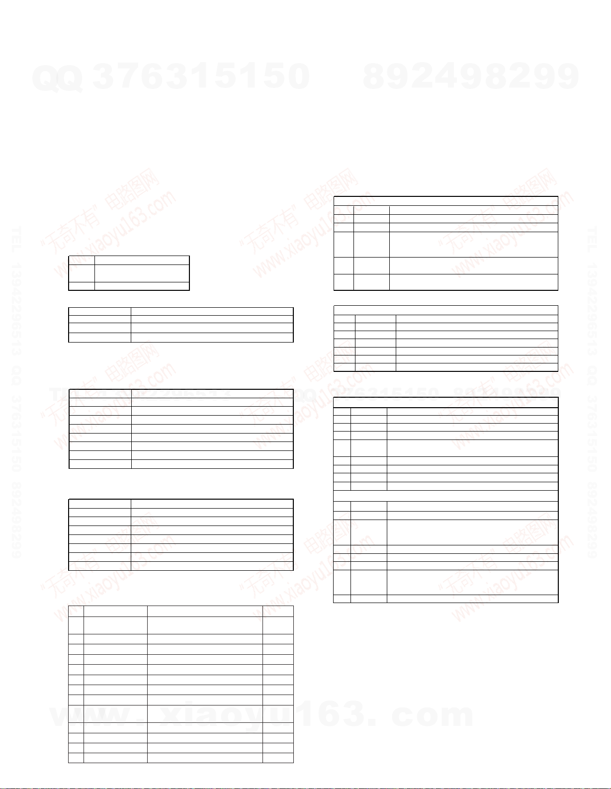
Key Description
O.T.E. [LCD (LED)]
[all on (blink)] or [off (off)]
STOP Cancel of mode
Key Operation
UP/DOWN Select parameter and mode.
PLAY Fix items. Change of display in every check.
STOP Cancel or back of test mode.
Key Operation
DOWN(SHIFT+) Select servo of PIT or GROOVE
PLAY(SHIFT+) Servo on
REC Pickup stops to move. Skip modes.
STOP(SHIFT+) Servo off
MODE Display change.
UP(SHIFT+) Servo on/off
F F Pickup moves outwards when press FF key
F B Pickup moves inwards when press FB key
(SHIFT+): Show the "SHIFT" on the display by pressing the O.T.E. key
1. Setting of Continuous Playback Mode
No. Key
1 UP/DOWN Select [CPLAY MODE]
2 Load disc
3 PLAY [CPLAY MID]
[c=xxxx a=yy] error
(xxxx=C1 error, yy=ADIP error)
4 MODE [CPLAY(zzzz)] CPLAY address
(MID=0300h, OUT=0700h, IN=0030h cluster)
5 MODE [h✽✽✽✽d@@@@] address
(✽✽✽✽=current head address, @@@@=ADIP address)
In No.5, Display shows [-] if can't read disc.
2. Change of Playback Points(in continuous playback mode)
No. Key
Display/Function
Display/Function
1 PLAY [CPLAY OUT]
2 Carry out No.4 and 5 in the above table.
3 PLAY [CPLAY IN]
4 Carry out No.4 and 5 in the above table.
5 STOP [CPLAY MODE]
6 EJECT Disc out
1. Continuous Recording Setting
No. Key Display/Function
1 UP/DOWN Select [CREC MODE]
2 Load the recordable disc
3 PLAY [CREC MID]
4 PLAY [CREC (zzzz)] CREC address
(0300h cluster=recording start point)
5 MODE [h✽✽✽✽d@@@@] address
6 MODE [c=xxxx a=yy] error
7 MODE [CREC (zzzz)]
8 STOP [c=xxxx a=yy]
2. Change and End of Recording Points
1 Carry out No.1 to 3 in the above table Select[CREC MID]
2 UP [CREC OUT]
3 PLAY [CREC (zzzz)] CREC address
(0700h cluster=recording start point)
Carry out No.5 to 8 in the above table
4 Carry out No.1 to 3 in the above table
5 PLAY Select [CREC MID]
6 UP(twice) Select [CREC IN]
7 PLAY [CREC (zzzz)] CREC address
(0300h cluster=recording start point)
Carry out No.5 to 8 in the above table
8 EJECT Disc out
Starting address is the followings.
IN=30h cluster, MID=300h cluster, OUT=700h cluster
LCD Display Descriptions
PLAY(logo) Servo on
PAUSE(logo) Tracking servo on
REC(logo) Record (laser write power)
GRV Servo groove mode
CLV-S Rough servo clock
CLV-A Spindle lock
RECORD Recordable disc or no disc
For more information on each adjustment mode, refer to
each section of 6, "Electrical adjustment".
If other adjustment mode has been entered incorrectly,
press the STOP key to exit the mode.
* The number 9 - 13 are not used for service. If these
mode have been entered incorrectly, press the STOP
key immediately to exit the mode. Specially, do not use
EEP INITIAL. (E2PROM data has initialized if used it.)
5-4 Selection of test mode
13 test modes are selected by pressing UP/DOWN keys.
1. The recording start addresses of IN, MID, and OUT
are described below.
IN 30H cluster
MID 300H cluster
OUT 700H cluster
2. An erasure prevention control is not detected in the
test mode. Be careful not to enter the continuous
recording mode using a disc containing the data that
should not be erased.
3. Do not record continuously for more than five
minutes.
4. Take care that no vibration is applied during
continuous recording.
No. Display Description Section
1 TEMP ADJUST The work of adjustment is 6-5
unnecessary in this mode
2 LDPWR ADJUST Laser power adjustment 6-6
3 LDPWR CHECK Laser power check 6-6
4 EFBAL ADJUST Traverse adjustment 6-7
6 FBIAS ADJUST Focus bias adjustment 6-8
5 TE B. ADJUST Automatic EF balance adjustment.
7 CPLAY MODE Continuous playback mode 5-5
8 CREC MODE Continuous recording mode 5-6
9 STT-LIMIT SW Check the mechanism start –
limit SW position
10 JUMP MODE Track jump checking mode –
11 SRV DAT READ Servo data reading –
12 EEP MODE E2PPROM data reading or rewrite –
13 EEP INITIAL E2PROM data initializing –
5. TEST MODE
5-1 How to Setting and Cancel Test Mode
Setting: While pressing the ON/STANDBY and MODE
keys, insert the power cord to the wall outlet.
Cancel: Pull out the power cord.
Mechanism Initialization
Setting: While pressing the EJECT key, insert the power
cord to the wall outlet.
Display shows [INITIALIZE]. Mechanism is in normal
mode after unload the disc if it loaded
Display
Setting: While pressing the MODE key, insert the power
cord to the wall outlet.
Cancel: Pull out the power cord.
Key Operation for Ajustment
5-2 Remaind Keys Operation
Caution: Data of E2PROM will be erased if pressed
O.T.E. key for more 3seconds.
5-3 Display of Mechanism operation in Test Mode
5-5 Continuous Playback Mode
5-6 Continuous Recording Mode
1p 99.10.293:45PM y[W 5
w
w
w
.
x
i
a
o
y
u
1
6
3
.
c
o
m
Q
Q
3
7
6
3
1
5
1
5
0
9
9
2
8
9
4
2
9
8
T
E
L
1
3
9
4
2
2
9
6
5
1
3
9
9
2
8
9
4
2
9
8
0
5
1
5
1
3
6
7
3
Q
Q
TEL 13942296513 QQ 376315150 892498299
TEL 13942296513 QQ 376315150 892498299