manuals.online logo
Brands
  1. Home
  2. •
  3. Brands
  4. •
  5. Kenwood
  6. •
  7. Repeater
  8. •
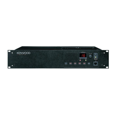
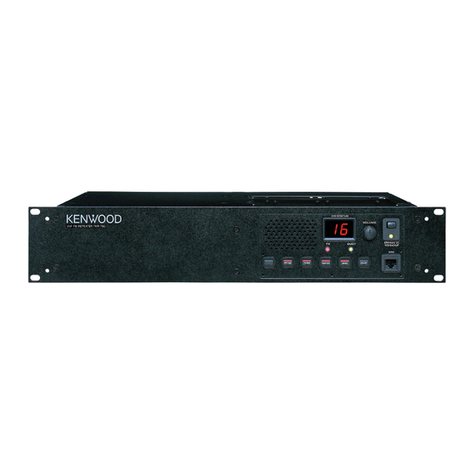
  9. Kenwood TKR-820 User manual

Kenwood TKR-820 User manual

Other manuals for TKR-820

1

Other Kenwood Repeater manuals

Kenwood NXR-5700 User manual

Kenwood

Kenwood NXR-5700 User manual

Kenwood Nexedge NXR-710-K User manual

Kenwood

Kenwood Nexedge NXR-710-K User manual

Kenwood TKR-850 User manual

Kenwood

Kenwood TKR-850 User manual

Kenwood Nexedge NXR-900 User manual

Kenwood

Kenwood Nexedge NXR-900 User manual

Kenwood NEXEDGE NXR-800 User manual

Kenwood

Kenwood NEXEDGE NXR-800 User manual

Kenwood NXR-5700-E User manual

Kenwood

Kenwood NXR-5700-E User manual

Kenwood NEXEDGE NXR-810 User manual

Kenwood

Kenwood NEXEDGE NXR-810 User manual

Kenwood NEXEDGE NXR-710-E User manual

Kenwood

Kenwood NEXEDGE NXR-710-E User manual

Kenwood NXR-5700 User manual

Kenwood

Kenwood NXR-5700 User manual

Kenwood NEXEDGE NXR-700 User manual

Kenwood

Kenwood NEXEDGE NXR-700 User manual

Kenwood TKR-7400S User manual

Kenwood

Kenwood TKR-7400S User manual

Kenwood TKR-851 Operating manual

Kenwood

Kenwood TKR-851 Operating manual

Kenwood TKR-820/N/A User manual

Kenwood

Kenwood TKR-820/N/A User manual

Kenwood TKR-D810 User manual

Kenwood

Kenwood TKR-D810 User manual

Kenwood NEXEDGE NXR-710 User manual

Kenwood

Kenwood NEXEDGE NXR-710 User manual

Kenwood NEXEDGE NXR-700 User manual

Kenwood

Kenwood NEXEDGE NXR-700 User manual

Kenwood NEXEDGE NXR-800 User manual

Kenwood

Kenwood NEXEDGE NXR-800 User manual

Kenwood NEXEDGE NXR-710 User manual

Kenwood

Kenwood NEXEDGE NXR-710 User manual

Kenwood NEXEDGE NXR-710 User manual

Kenwood

Kenwood NEXEDGE NXR-710 User manual

Kenwood TKR-720(N) User manual

Kenwood

Kenwood TKR-720(N) User manual

Kenwood TKR-751 User manual

Kenwood

Kenwood TKR-751 User manual

Kenwood NEXEDGE NXR-800-K4 User manual

Kenwood

Kenwood NEXEDGE NXR-800-K4 User manual

Kenwood TKR-851 User manual

Kenwood

Kenwood TKR-851 User manual

Kenwood TKR-740 User manual

Kenwood

Kenwood TKR-740 User manual

Popular Repeater manuals by other brands

Asus RP-AC51 quick start guide

Asus

Asus RP-AC51 quick start guide

Exibel HRP0101 instruction manual

Exibel

Exibel HRP0101 instruction manual

York Universal LINC485 installation manual

York

York Universal LINC485 installation manual

MIKOM MRx01B Power Series user manual

MIKOM

MIKOM MRx01B Power Series user manual

Simrad RD 301 instruction manual

Simrad

Simrad RD 301 instruction manual

Inventronics DALI REPEATER SO operating instructions

Inventronics

Inventronics DALI REPEATER SO operating instructions

XFP 16 installation manual

XFP

XFP 16 installation manual

Andrew MRx18 user manual

Andrew

Andrew MRx18 user manual

COMBA RXA3748 user manual

COMBA

COMBA RXA3748 user manual

ADRF SDR-ICS-43 user manual

ADRF

ADRF SDR-ICS-43 user manual

Teltonika WRP100 user manual

Teltonika

Teltonika WRP100 user manual

U-Prox HW installation manual

U-Prox

U-Prox HW installation manual

Motorola VRS750 Service manual

Motorola

Motorola VRS750 Service manual

KanexPro SDI-HDRPTPRO user manual

KanexPro

KanexPro SDI-HDRPTPRO user manual

Ltech LT-3030-CС quick start guide

Ltech

Ltech LT-3030-CС quick start guide

Gigaset 108 owner's manual

Gigaset

Gigaset 108 owner's manual

Intellinet IPE-IND instructions

Intellinet

Intellinet IPE-IND instructions

Ltech LT-3090-1050 manual

Ltech

Ltech LT-3090-1050 manual

manuals.online logo
manuals.online logoBrands
  • About & Mission
  • Contact us
  • Privacy Policy
  • Terms and Conditions

Copyright 2025 Manuals.Online. All Rights Reserved.

SERVICE
MANUAL
©
1990-3
PRINTED
IN
JAPAN
B51-8050-00
(O)
1403
REVISED
Panel
Case
(Upper)
Dressing
plate
Knob
(TAKE
OVER,
REPEAT,
MONI)
(A20-2666-11)}
(A01-1059-01)
(A21-1519-03)
(K29-3148-04)
x
3
Knob
(POWER)
Foot
Knob
(VOL,
SQL)
Dressing
plate
Rectangular
receptacle
(MIC)
(K29-31
46-04)
(J02-0049-14)
x
4
(K29-3147-03)
x
2
(A21-1520-03)
(E08-0673-05)
CONTENTS
GENERAL
.........ccccsceececeeesseesesscecescsencerceeeuserssseceeneestes
2
RX
VCO
:
Z2
(X58-3150-XX)
wesscseccecesseecnsenssrseesene
63
SYSTEM
SET-UP
.........:sscscessscstsrnssssccuseseserenseeseers
4
TX
VCO
:
Z5
(X58-B460-XX)
....eecreeceseersseessnsscereue
64
INSTALLATION
......0..cceccsssessesssensessensccescersssseneaeeeeeses
5
MIC
AMP
:
Z7
(X59-3210-10)
....scccssececesnsereseeen
-
65
CONVERSION
.........-cccsssesceeeetsessccevensssseceusvsseneesssssees
9
IF
:
ZB
(X59-3220-1O)
...
ee
eesecesssnssteteeeeseensneesneneetan
-
66
DISASSEMBLY
FOR
REPAIR
.............::sccsseessereees
11
BPF
/
VCA
:
Z9
(X59-3230-10)
...sccsesessrsrsesssereenn
-
67
BLOCK
DIAGRAM
............--:::scssccrsercessersetseeneecsenens
17
AVR
UNIT
(X43-3040-10)
oo...
ccseeesseseesssteesseeeeeene
-
68
CIRCUIT
DESCRIPTION
.............ceccssssesssersseeessereees
19
FINAL
UNIT
(X45-3250-XX)
...cssseccceeeeessecenstseeene
-
70
SEMICONDUCTOR
DATA
..........::cecccssscssesenteseseees
26
SIGNALING
UNIT
(X52-3140-10)
.....eceesstceesseren
-72
DESCRIPTION
OF
COMPONENTS
............scsceeees
31
DISPLAY
UNIT
(X54-3070-11)
.eecscccccccssreeneessenn
~
74
PARTS
LIST
........::cccescseeceescenseeresnnseneneceesscersscasenenses
33
TX-RX
UNIT
(X57-3270-XX)
oo
ecessessssseessceesesseneenn
-
78
DISASSEMBLY
.........ccscsssscccresenensessonnseusessconeresenses
53
SIGNALING
CIRCUIT
DIAGRAM
.................00008
-
83
PACKING
..........ccssssscssesseneescsesseccceeesssseosenancansrsseneses
55
SCHEMATIC
DIAGRAM
............ccssseesececssessenernennn
-
87
ADJUSTMENT
........:ccccccscsccorccessesusenscnscunsnrsesenezetsss
56
TERMINAL
FUNCTIONG.
.............:ccceeeeecesersencoeeens
~
95
PC
BOARD
VIEWS
/
CIRCUIT
DIAGRAMS
KMC-9
(BASE
MICROPHONE)
...........--cccsecsoeeetene
-
97
RX
PLL:
Z1,
TX
PLL
:
Z4
(X58-3120-10)
....sececees
62
SPECIFICATIONS.
...........csssscsseresessees
BACK
COVER
TKR-820
GENERAL
INTRODUCTION
SCOPE
OF
THIS
MANUAL
This
manual
is
intended
for
use
by
experienced
techni-
cians
familiar
with
similar
types
of
commercial
grade
com-,
munications
equipment.
It
contains
all
required
service
information
for
the
equipment
and
is
current
as
of
the
pub-
licatton
date.
Changes
which
may
occur
after
publication
are
covered
by
either
Service
Bulletins
or
Manual
Revi-
sions.
These
are
issued
as
required.
ORDERING
REPLACEMENT
PARTS
When
ordering
replacement
parts
or
equipment
infor-
mation,
the
full
part
identification
number
should
be
included.
This
applies
to
all
parts:
components,
kits,
or
chassis.
If
the
part
number
is
not
known,
include
the
chas-
sis
or
kit
number
of
which
it
is
a
part,
and
a
sufficient
de-
scription
of
the
required
component
for
proper
identifica-
tion.
PERSONNEL
SAFETY
The
following
precautions
are
recommended
for
personnel
safety:
@
DO
NOT
transmit
if
someone
is
within
two
feet
(0.6
meter)
of
the
antenna.
@
DO
NOT
transmit
until
all
RF
connectors
are
verified
secure
and
any
open
connectors
are
properly
ter-
minated.
@
SHUT
OFF
and
DO
NOT
operate
this
equipment
near
electrical
blasting
caps
or
in-an
explosive
atmosphere.
@
All
equipment
should
be
properly
grounded
before
power-up
for
safe
operation
@
This
equipment
should
be
serviced
by
a
qualified
tech-
nician
only.
®
Be
careful
against
electric
hazard,
for
the
commercial
power
supply
is
being
applied
to
the
internal
circuitry
of
the
radio
even
when
the
Power
switch
is
OFF.
FCC
COMPLIANCE
AND
TYPE
NUMBERS
Type
acceptance
number
|-Frequency
range
Compliance
ALHSTKTKR-820-1
450
to
470MHz
Part
22, 74,
90
and
95A
ALHTKR-820-2
470
to
490MHz
Part
22,
74
and
90
ALHTKR-820-3
490
to
512MHz
Part
22,
74
and
90
ALHTKR-820-4
406
to
430MHz
Part
90
1.
POWER-UP
To
push
on
the
radio.
The
POWER
indicator
will
illuminate
to
indicate
power
is
ON.
2.
TO
RECEIVE
Operation
Procedure
1.
Disable
OT
Push
on
MONITOR
switch.
If
so
programmed.
Turn
SQUELCH
control
counter-
clockwise
until
noise
is
heard.
2.
Unsquelch
radio
3.
Set
VOLUME
control
Adjust
VOLUME
control
for
a
normal
listening
level.
4.
Set
SQUELCH
control
Advance
SQUELCH
control
clock-
wise
until
noise
just
stops.
The
radio
will
now
receive
all
traffic
on
the
selected
channel.
5.
Enable
OT
Press
the
MONITOR
switch
to
OFF.
1f
so
programmed.
You
will
now
hear
messages
for
your
system
only.
3.
TO
TRANSMIT
(in
case
a
microphone
is
connectect}
Operation
Procedure
1.
Disable
QT
Depress
MONITOR
switchon
front
panel
or
Microphone.
2.
LISTEN
DO
NOT
TRANSMIT
if
channel
is
in
use,
Press
and
hold
the
microphome
PTT
switch.
The Red
LED
on
the
front
panel
will
glow
indicating
he
trans-
mitter
is
ON.
3.
Key
transmitter
Hold
microphone
at
about2
inches
distance
and
speak
at
a
nom
al
voice
level.
Keep
transmissions
bief.
-
4.
Transmit
message
5.
Receive
reply
Release
the
microphone
PTT
switch.
6.
Enable
OT
at
end
of
the
conversation
Hf
so
programmed.
Depress
MONITOR
to
theoust
position.
TKR-820
GENERAL
4.
DURING
OPERATION
OF
REPEATER
Operation
Procedure
1.
Enable
repeat
Press
the
REPEAT
switch
to
ON.
When
a
signal
including
the
abject
tone
signal
(provided
that
it
has
been
programmed)
is
input
and
if
its
level
is
higher
than
the
preset
squelch
level,
a
signal
modulated
by
the
set
tone
signal
(provided
that
it
has
been
pro-
grammed)
and
received
audio
signal
is
transmitted.
2.
Start
of
repeat
When
the
received
signal
disappears,
the
transmission
is
stopped
after
the
set
period
of
time.
There
indicator
lights
while
the
signal
is
transmitted.
3.
End
of
repeat
Press
the
REPEAT
switch
again
to
OFF.
4.
Disable
repeat
PRE-INSTALLATION
CONSIDERATIONS
1.
UNPACKING
Unpack
the
radio
from
its
shipping
container
and
check
for
accessory
items.
If
any
item
is
missing,
please
contact
KENWOOD
immediately.
2.
LICENSING
REQUIREMENTS
Federal
regulations
require
a
station
license
for
each
radio
installation
(mobile
or
base)
be
obtained
by
the
equipment
owner.
The
licensee
is
responsible
for
ensuring
transmitter
power,
frequency,
and
deviation
are
within
the
limits
permitted
by
the
station
license.
Transmitter
adjustments
may
be
performed
only
by
a
licensed
technician
holding
an
FCC
first,
second
or
general
class
commercial
radiotelephone
operator's
license.
There
iS
NO
license
required
to
install
or
operate
the
radio.
3.
PRE-INSTALLATION
CHECKOUT
3-1.
Introduction
Each
radio
is
adjusted
and
tested
before
shipment.
However,
it
is
recommended
that
receiver
and
transmitter
operation
be
checked
for
proper
operation
before
installa-
tion.
3-2.
Testing
The
radio
should
be
tested
complete
with
all
cabling
and
accessories
as
they
will
be
connected
in
the
final
installation.
Transmitter
frequency,
deviation,
and
power
output
should
be
checked,
as
should
receiver
sensitivity,
squelch
operation,
and
audio
output.
QT
equipment
opera-
tion
should
be
verified.
4.
PLANNING
THE
INSTALLATION
4-1.
General
Inspect
the
vehicle
and
determine
how
and
where
the
radio
antenna
and
accessories
will
be
mounted.
Plan
cable
runs
for
protection
against
pinching
or
crushing
wiring,
and
radio
installation
to
prevent
overheat-
ing.
4-2.
Antenna
When
an
outdoor
antenna
is
to
be
installed,
select
an
unobstructed
position
with
good
visibility.
The
VSWR
of
the
antenna
should
be
no
more
than
2.
Select
a
coaxial
cable
with
as
small
Joss
as
possible,
and
its
length
should
be
as
short
as
possible.
4-3.
Radio
Install
the
radio
on
a
rack
using
rack-mount
brackets,
or
on
a
flat
surface
that
can
withstand
its
weight.
Do
not
install
the
radio
in
a
place
subject
to
direct
sunlight
or
near
heating
equipment.
Avoid
wet
place,
and
install
it
ina
well-
ventilated
place.
4-4.
AC
power
supply
This
unit
has
been
designed
for use
exclusively
with
commercial
AC
power
supply.
As
the
rated
current
for
transmission
output
attains
about
2A,
connect
the
unit
to
a
wall
outlet
that
can
handle
this
current
with
margin.
SERVICE
This
radio
is
designed
for
easy
servicing.
Referto
the
schematic
diagrams,
printed
circuit
board
views,
and
alignment
procedures
contained
in
this
manual.
TKR-820
Merchandise
received
h
SYSTEM
SET-UP
Preparation
:
Prepare
an
EEPROM
writer,
KPT-20.
License
and
frequency
allocated
by
FCC
Frequency
range
|
RF
Power
Type
450
~
470MHz
25W
TKR-820
K,M
Choose
the
type
of
_
470
~
490MHz
25W
TKR-820
K2,M2
transceiver
490
~
512MHz
25wW
|
TKR-820
K3
490
~
520MHz
25W
TKR-820
M3
406
~
430MHz
25W
TKR-820
K4
See
KPT-20
400
~
430MHz
25W
TKR-820
M4
Frequency,
Instruction
EEPROM
writer
manual.
q
See
KPT-20
Instruction
Signaling
DATA
manuat.
EEPROM
writer
{for
Signaling
unit)
See
page
5.
EEPROM
installation
Duplexer
used?
See
page
6.
Duplexer
*
installation
“Option
__|
DC
Back
up
modification
Parts
used?
See
page
9,
OC
Back
up
modification
J
Mounting
Bracket
used?
NO
See
page
8.
Mounting
Bracket
installation
|
Delivery
TKR-820
INSTALLATION
Installing
the
EEPROM
of
Signaling
Unit
Note
:EEPROM
is
inserted
into
the
Signaling
unit
of
the
TKR-820.
Install
it
after
writing
the
data
using
the
ROM
writer
(KPT-20).
1.
Remove
the
10
screws
(‘®@)
holding
the
upper
case
to
remove
the
upper
case.
2.
Remove
the
11
screws
(
@)
retaining
the
shield
cover
to
remove
the
shield
cover.
2)
3.
Insert
the
EEPROM
(®)
on
which
the
data
has
been
Shield
cover
g
written
into
the
IC
socket
(IC10)}
on
the
Signaling
unit.
iC(EEPROM)
93C46?1
TKR-820
INSTALLATION
Installing
the
Duplexer
Note
:When
installing
the
duplexer
in
the
TKR-820,
use
the
either
of
the
following
products
;
1.
CELWAVE
(USA),
435
to
470MHz
(PD633-6A)
2.
ANTEN
CORPORATION
(JAPAN),
450
to
470MHz
(L79-0691-05)
400
to
430MHz
(L79-0896-05)
1.
Remove
the
10
screws
(‘@)
holding
the
upper
case
to
remove
the
upper
case.
2.
Remove
the
4
screws
(‘@)
holding
the
lower
case
to
remove
the
lower
case.
3.
After
removing
the
upper
and
lower
cases,
turn
the
set
upside
down,
as
shown
in
the
figure
3)
).
4.
Remove
the
coaxial
cables
(@).
@)
connected
to
the
TX
and
RX
antenna
connectors.
TX
Antenna
connector
RX
Antenna
connector
a
=
TKR-820
INSTALLATION
(‘@)
and
the
8
screws
C7)
)
provided
with
the
set.
6,
Connect
the
one
end
of
the
connector
cabel
(@)
pro-
vided
with
the
set
to
the
duplexer
antenna
connector
o
and
the
other
end
to
the
ANT
(center)
of
the
duplexer.
{
TF
=)
7.
Connect
the
connector
cable
(®)
wired
from
the
TX
é
lh
i
|
section
and
the
connector
cable
(®)
wired
fram
the
O--~@
[>
C]
|
5.
Mount
the
duplexer
‘@)
using
the
mounting
hardware
y——
Duplexer
Antenna
connector
u
RX
section
to
the
duplexer.
[o]
00%
ex.
©)
a
CELWAVE'S
Duplexer
°
_
eO@
9
tre
vo
todh
*
=
|
on
a
=
Note
:The
input/output
connectors
of
the
duplexer
manu-
facture
by
CELWAVE
or
ANTEN
are
located
as
REC.
ANT
TRANS.
LOW
ANT
HIGH
shown
in
the
figure.
Pay
attention
when
connecting
eth
it
__.2,
afk,
Te
the
connectors
(as
input/output
location
is
reversed).
°
o
°
oO
°
rs)
° °
ie) ie} ie)
o
CELWAVE’S
Duplexer
ANTEN’S
Duplexer
Note
:When
making
adjustments
after
installing
the
duplexer,
remove
the
front
panel
and
hold
down
the
sub-pane!
(®),
then
perform
adjustments
from
the
adjusting
holes
().
KR-820
INSTALLATION
Attaching
the
Rack-mount
Brackets
(for
EIA
racks)
The
brackets
and
screws
are
optional.
Brackets
:
J21-4250-04
(Common
for
left
and
right)
Screws
:
NO9-0704-05
(Use
2
screws
per
bracket)
1.
Attach
the
2
brackets
(@)
using
4
screws
(‘®).
2.
When
the
TKR-820
is
to
be
mounted
vertically
:
Attach
4
brackets
(@),
using
8
screws
(@}),
to
the
sides
of
the
bottom
panel.
7
SS
SN
©
4
ia
6
TKR-820
CONVERSION
Modification
of
the
DC
Switching
Circuit
(For
Backup
during
a
Power
Failure)
TKR820
A
L
The
following
parts
(optional)
are
required
for
the
Fe
circuit
modification.
WUT
[|
|]
_O©_
|
pine
|
Diode
($25VB10)
..........
000000.
1
pe.
Cit)
DC
cable
(E30-2076-10)
.............
1
pe.
Connector
with
lead
wires
(E31-3389-05)
..
1
pc.
COMO!
Connector
with
lead
wires
(E31-3455-05)
..
1
pe.
oS
Screw
(N87-4014-46)
.........00
0084
1
pe.
1.
From
the
cover
(‘®)
attached
to
the
rear
panel,
remove
the
2
screws
‘@)
and
take
off
the
cover.
®
I
ia
:
a
_)
Jt
L}—}-—L_}
©
9K;
©
°
|
©
[le
2.
Insert
the
connector
with
lead
wires
(
@)
into
the
hole
m
on
the
rear
panel
‘@)
(so
that
the
red
lead
is
on
the
right).
3.
Place
the
diode
(
@)
so
that
its
notch
faces
the
direc-
a)
|
tion
shown
in
the
illustration,
and
attach
it
using
a
|
screw
(@).
C2
|
|
|
4,
Disconnect
the
connector
(@)
from
the
QUT
terminal
of
the
AVR
unit,
and
connect
its
lead
wire
to
pin
1
of
a
5
i
0
ou
the
diode
(
).
B
8B
°
our)
4
SS
ae
Red
lead
@|
i
=
iC
TKR-820
CONVERSION
5.
Connect
the
optional
connector
with
lead
wires
(
©)
to
f
the
OUT
terminal
of
the
AVR
unit
and
to
pin
3
of
the
diode.
a)
6.
Connect
the
red
lead
(©)
of
the
optional
connector
with
lead
wires
to
pin
2
of
the
diode,
and
its
black
lead
(®)
to
the
negative
(—}
terminal
of
chemical
capacitor
C101.
Do
not
disconnect
the
lead
wire
which
has
been
\
connected
to
the
C101
negative
terminal,
but
connect
the
black
lead
to
it.
7.
Connect
the
optional
DC
cable
to
the
connector
on
the
rear
panel
(®).
TKR-820
10