manuals.online logo
Brands
  1. Home
  2. •
  3. Brands
  4. •
  5. Kenwood
  6. •
  7. Stereo Receiver
  8. •
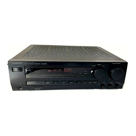
  9. Kenwood 103AR User manual

Kenwood 103AR User manual

Other manuals for 103AR

4

Other Kenwood Stereo Receiver manuals

Kenwood KR-7600 User manual

Kenwood

Kenwood KR-7600 User manual

Kenwood KRF-V7070D User manual

Kenwood

Kenwood KRF-V7070D User manual

Kenwood KRF-V7771D User manual

Kenwood

Kenwood KRF-V7771D User manual

Kenwood CT-201/KXF-W1010 User manual

Kenwood

Kenwood CT-201/KXF-W1010 User manual

Kenwood KRF-V5050D User manual

Kenwood

Kenwood KRF-V5050D User manual

Kenwood VR-716A Quick start guide

Kenwood

Kenwood VR-716A Quick start guide

Kenwood 1080VR User manual

Kenwood

Kenwood 1080VR User manual

Kenwood KRF-V4060D User manual

Kenwood

Kenwood KRF-V4060D User manual

Kenwood KRF-V6060D User manual

Kenwood

Kenwood KRF-V6060D User manual

Kenwood KR-V8080 User manual

Kenwood

Kenwood KR-V8080 User manual

Kenwood KRF-X9090D User manual

Kenwood

Kenwood KRF-X9090D User manual

Kenwood KR-1000B User manual

Kenwood

Kenwood KR-1000B User manual

Kenwood KR-V9020 User manual

Kenwood

Kenwood KR-V9020 User manual

Kenwood KR-3200 User manual

Kenwood

Kenwood KR-3200 User manual

Kenwood KR-595 User manual

Kenwood

Kenwood KR-595 User manual

Kenwood C-V751 User manual

Kenwood

Kenwood C-V751 User manual

Kenwood KR-V8050 User manual

Kenwood

Kenwood KR-V8050 User manual

Kenwood KRC-508S User manual

Kenwood

Kenwood KRC-508S User manual

Kenwood KRF-X9050D User manual

Kenwood

Kenwood KRF-X9050D User manual

Kenwood KR-V80 User manual

Kenwood

Kenwood KR-V80 User manual

Kenwood VR-2090 User manual

Kenwood

Kenwood VR-2090 User manual

Kenwood KRF-V8090D User manual

Kenwood

Kenwood KRF-V8090D User manual
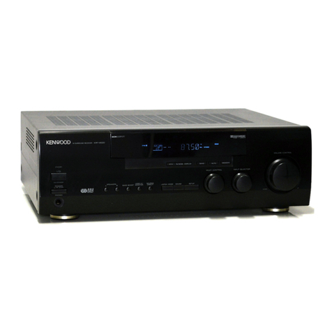
Kenwood KR-V8090 User manual

Kenwood

Kenwood KR-V8090 User manual

Kenwood VR Series User manual

Kenwood

Kenwood VR Series User manual

Popular Stereo Receiver manuals by other brands

Teac AG-680 Service manual

Teac

Teac AG-680 Service manual

Teac AGV1050 owner's manual

Teac

Teac AGV1050 owner's manual

Sony STR-435 operating instructions

Sony

Sony STR-435 operating instructions

Pioneer Elite SC-68 Service manual

Pioneer

Pioneer Elite SC-68 Service manual

Pioneer SX-1250 operating instructions

Pioneer

Pioneer SX-1250 operating instructions

Marantz CINEMA 70S owner's manual

Marantz

Marantz CINEMA 70S owner's manual

Yamaha RX-830 owner's manual

Yamaha

Yamaha RX-830 owner's manual

Pioneer AVH-Z7250BT owner's manual

Pioneer

Pioneer AVH-Z7250BT owner's manual

Denon AVR-1311 owner's manual

Denon

Denon AVR-1311 owner's manual

Denon AVR-S760H owner's manual

Denon

Denon AVR-S760H owner's manual

Denon AVR-X7200W Service manual

Denon

Denon AVR-X7200W Service manual

Sony XAV-1500 operating instructions

Sony

Sony XAV-1500 operating instructions

Radio Shack DX-399 owner's manual

Radio Shack

Radio Shack DX-399 owner's manual

Sony STR-DE535 - Fm Stereo/fm-am Receiver operating instructions

Sony

Sony STR-DE535 - Fm Stereo/fm-am Receiver operating instructions

Pioneer SX-1000TA operating instructions

Pioneer

Pioneer SX-1000TA operating instructions

Yamaha MusicCast TSR-5B3D owner's manual

Yamaha

Yamaha MusicCast TSR-5B3D owner's manual

Sony STR-DG500 - Multi Channel Av Receiver Service manual

Sony

Sony STR-DG500 - Multi Channel Av Receiver Service manual

Sherwood Newcastle RX-770 operating instructions

Sherwood

Sherwood Newcastle RX-770 operating instructions

manuals.online logo
manuals.online logoBrands
  • About & Mission
  • Contact us
  • Privacy Policy
  • Terms and Conditions

Copyright 2025 Manuals.Online. All Rights Reserved.

KENWOOD
AM-FM
STEREO
RECEIVER
103AR
INSTRUCTION
MANUAL
KENWOOD
CORPORATION
B60-3188-10
(gS)(K,
P,
Y)
;MCj
97/12
11
1098765432
Before
applying
power
Caution:
Read
this
section
carefully
to
ensure
safe
operation.
Units
are
designed
for
operation
as
follows.
«
U.S.A.
and
Canada
.
A
C
120
V
only
Australia
.
A
C
240
V
only
China
.
A
C
220
V
only
*
Other
countries
.
A
C
110-120/220-240
V
switchable
*AC
voltage
selection
The
AC
voltage
selector
switch
on
the
rear
panel
is
set
to
the
voltage
that
prevails
in
the
area
to
which
the
unit
is
shipped
Before
connecting
the
power
cord
to
your
AC
outlet,
make
sure
that
the
setting
position
of
this
switch
matches
your
line
voltage
If
not,
it
must
be
set
to
your
voltage
in
accordance
with
the
fol¬
lowing
direction.
AC
voltage
selector
switch
Our
warranty
does
not
cover
damage
caused
by
excessive
line
voltage
due
to
improper
setting
of
the
AC
voltage
selector
switch.
ffljiooOOO'-j
r
o.oooo-i
Move
switch
lever
to
match
your
line
voltage
with
a
small
screwdriver
or
other
pointed
tool.
Sa
fety
precautions
A
Caution:
Read
this
section
carefully
to
ensure
safe
operation.
WARNING:
TO
PREVENT
FIRE
OR
ELECTRIC
SHOCK,
DO
NOT
EXPOSE
THIS
APPLIANCE
TO
RAIN
OR
MOISTURE.
/ik.
CAUTION
RISK
OF
ELECTRIC
SHOCK
DO
NOT
OPEN
A
A
A
CAUTION:
TO
REDUCE
THE
RISK
OF
ELECTRIC
SHOCK,
DO
NOT
REMOVE
COVER
(OR
BACK)
NO
USER-SERVICEABLE
PARTS
INSIDE,
REFER
SERVICING
TO
QUALIFIED
SERVICE
PERSONNEL.
THE
LIGHTNING
FLASH
WITH
ARROWHEAD
SYMBOL,
WITHIN
AN-EQUILATERAL
TRIANGLE,
IS
INTENDED
TO
ALERT
THE
USER
TO
THE
PRESENCE
OF
UNINSULATED
"DANGEROUS
VOLTAGE"
WITHIN
THE
PRODUCT'S
ENCLOSURE
THAT
MAY
BE
OF
SUFFICIENT
MAGNITUDE
TO
CONSTITUTE
A
RISK
OF
ELECTRIC
SHOCK
TO
PERSONS.
T
H
E
EXCLAMATION
POINT
WITHIN
AN
EQUILATERAL
TRIANGLE
IS
INTENDED
TO
ALERT
THE
USER
TO
THE
PRESENCE
OF
IMPORTANT
OPERATING
AND
MAINTENANCE
(SERVICING)
INSTRUCTIONS
IN
THE
LITERATURE
ACCOMPANYING
THE
APPLIANCE.
Unpacking
Imnar-
me
u''T
ca
r
e
f
u
uv
and
maxe
su
r
e
"'a*
al
accessories
are
put
aside
so
they
will
not
be
lost.
Examine
the
unit
for
any
possibility
of
sn
cc"
a
asm
eye
!
*
your
jmt
is
oamagea
c
tars
to
operate,
notify
vou-
r
dealer
immediately.
If
your
unit
was
shipped
to
you
directly,
notify
me
s'
on
r
'Q
comnanv
vvdnout
de
ay
0•’
■
v
me
consignee
ire
person
or
company
receiving
the
unit)
can
file
a
claim
against
the
carrier
for
sn
opmg
damage
We
recommeno
that
yo..
'etam
the
oiiGina:
carton
and
packing
materials
for
use
snould
you
transport
or
ship
the
unit
in
the
t
u
t
-
1
fc
Accessories
FM
"'doc'
antenna
O
A
M
looo
ant
e
n
o
a
(1
1
Loop
antenna
stand
(1!
Remote
contrc
Batteries
(R6/AA)
(2)
103AR
(En)
Special
features
StatimMts
Remote
controllable
audio
function
,
r/r/s
unit
incorporates
a
function
for
stoi
preset
memory
with
a
simple
operation,
preset
the
stations
you
like.
The
preset
s
also
very
easily.
Setting
the
Speaker
Impedance
Selector
to
match
the
impedance
of
your
speakers
allows
you
to
take
full
advantage
of
you're
speaker's
performance
characteristics
by
driving
them
under
the
best
possible
conditions.
We've
also
included
2
sets
of
speaker
terminals
so
you
can
connect
two
different
sounding
speaker
systems,
or
use
two
sets
of
speakers
at
once
(only
when
both
sets
of
speakers
have
an
impedance
of
8
ohms
or
more).
-
,
6
,.
By
connecting
KENWOOD
source
components
such
as
a
cassette
deck
and
CD
player
through
system
control
connection,
the
basic
operations
of
these
components
can
be
controlled
from
the
remote
control
unit
provided
with
this
unit.
A
single
remote
control
unit
can
control
the
entire
audio
system
easily.
-
C
X
ring
received
stations
in
It
is
very
convenient
to
stations
can
be
recalled
Contents
Before
applying
power
Special
features
System
connections
Controls
and
indicators
Playing
music
Sound
adjustment
functions
Recording
Broadcast
reception
Caution
:
Read
the
pages
marked
A
carefully
to
ensure
safe
operation.
!
Before
applying
power
!
Safety
precautions
FM
DE-EMPHASIS
/
CHANNEL
SPACE
switch
Receiving
broadcast
stations..
Receiving
radio
stations
by
specifying
its
frequency
Storing
radio
stations
in
memory
(Station
preset)....
Receiving
a
preset
station
.
Receiving
all
preset
stations
in
order.
2
2
.
3
4
7
8
10
11
12
13
13
14
15
15
15
16
17
In
case
of
difficulty
!
Specifications
System
connections
Connections
of
Audio
and
Video
components
Make
connection
as
shown
below.
When
connecting
the
related
system
components,
refer
also
to
the
instruction
manuals
of
the
related
components.
Do
not
plug
in
the
power
lead
until
all
connections
are
completed.
Malfunction
of
microcomputer
if
operation
is
not
possible
or
erroneous
display
appears
even
though
all
connections
have
been
made
properly,
reset
the
microcomputer
referring
to
'In
case
of
difficulty'.
—
jjjT
Monitor
TV
Video
deck
or
LD
player
SYSTEM
CONTROL
jack
Used
for
system
control
connection
of
KENWOOD
com-
ponents.
-
X
@
System
control
cord
t
n
Yftt
SPEAKERS
IMPEDANCE
SELECTOR
To
wall
AC
outlet
For
U
S
A..
Canada
and
China
For
other
countries
(f$
0
^
Tape
deck
or
MD
recorder
Turntable
About
the
system
control
connections
1D3AR
[En)
«
•m
Connecting
system
control
cords
after
connecting
a
KENWOOD
audio
component
system
lets
you
take
advantage
of
convenient
system
control
operations.
There
are
two
KENWOOD
system
control
modes.
Make
connections
according
to
the
groups
of
terminal
symbols
shown
below.
Q(SBj
Mode:
lets
you
combine
DR],
DCS],
and
DCSB
terminals
GLIB
Mode:
for
5LE1
terminals
only
This
unit
is
compatible
with
both
(XS8J
and
[SL16]
modes
It
comes
from
the
factory
set
to
the
IXS8]
mode.
To
switch
to
the
[SL161
mode,
follow
the
instructions
in
"SWITCHING
FROM
[XS8]
TO
[SL16]"
below.
EXAMPLE:
[XS8]
mode
connections
The
underlined
portion
represents
the
setting
of
the
system
control
mode.
System
control
cord
System
control
cord
ISL16]
[XS8]
[SL16]
[SL16]
[XS]
[XS8]
[XR]
[SL16]
[XS]
[XS8]
[XS]
.
Seme
CD
D
aye's
a-a
cassette
decks
are
not
compat.oie
with
the
ISL16!
system,
control
mode.
Be
sure
to
use
tne
[XSSI
system
control
■
oo
e
wne-"
m
a
King
system
connections
with
eauipment
that
<s
not
(SL1
6]
compatible
•
Seme
MD
P'avers
am
not
system
control
compatible
You
cannot
make
system
control
connections
to
this
kind
of
equipment.
EXAMPLE:
[SL16]
mode
connections
The
underlined
portion
represents
the
setting
of
the
system
control
mode.
[SLT6}
[XS8]
[SL16]
[SL16]
[XS]
[XS8]
[XR]
[SL163
[XS]
[XS8]
[XS]
[SLl6i
equipment
cannot
be
combined
witr
[XRi.
[XS],
and
[XS8]
equipment
for
system
opera¬
tions
If
yOu
r
eou.oment
consists
of
this
moo
of
combinatton,
cpt
r
o
i
C0’ds.
Even
w
mom
system
comro
cords.
no
r
rVfectma
oer'omnancc
h
please
do
not
connect
any
system
■
a
;
operations
can
be
earned
out
without
no
’
connect
system
control
cords
to
any
components
other
than
those
specified
by
KENWOOD
It
may
cause
a
malfunction
and
damage
you'
equipment.
do
su
r
e
the
syste'"
control
Dluas
are
inserted
ali
the
way
m
to
the
system
control
terminals
ABOUT
THE
SYSTEM
CONTROL
OPERATIONS
Remote
Control
(Except
ISL
1
6
]
)
Lets
you
operate
source
components
with
the
system
re¬
mote
supplied
with
this
unit.
Automatic
Operation
(Except
[XR]
equipment)
When
you
start
playback
from
a
source
component,
the
in¬
put
selector
on
this
unit
switches
to
that
component
auto¬
matically
Synchronized
Recording
(Except
[XR]
equipment)
Lets
you
synchronize
recording
with
the
start
of
playback
when
recording
from
CD,
MD,
or
analog
discs
SWITCHING
FROM
[XS8J
TO
[SL
16]
You
can
easily
change
the
system
control
mode
with
the
following
operation.
Do
this
operation
after
completing
all
connections.
Switching
to
[SL16]:
Switching
back
to
[XS8]:
Unplug
the
AC
power
cord
from
the
wall
outlet,
then
plug
it
back
in
while
holding
down
the
AUTO/
MANUAL
key
Unplug
the
AC
power
cord
from
the
wall
outlet,
then
plug
it
back
in
while
holding
down
the
BAND
key
.
•
This
operation
wil
not
affect
items
stored
in
the
memory
Note]
Tne
system
control
mode
will
revert
to
[XS8]
if
the
cower
cord
is
disconnected
from
the
AC
outlet
for
th^ee
consecutive
aays.
If
you
would
like
to
make
:oe
unit
completely
(and
permanently)
JSL16]
com¬
patible.
please
consult
your
nearest
retailer
or
the
KENWOOD
Marketing
Department
1
Connect
all
Coras
firmiy
i!
connections
are
loose,
mere
could
be
loss
of
sound
or
noise
produced.
2
l\
-.e-
piuggmg
and
unplugging
connection
cords,
be
sure
to
first
remove
the
power
cord
from
the
AC
outlet
Ptuqqmq
/
unpluo-
cmg
connection
cords
without
removal
of
tne
aowe-
cord
car
cause
malfunctions
or
damage
to
the
unit
103AH
(En)
Connection
of
sneakers
Speaker
system
A
|
Speaker
protection
circuitry
j
'<
■
t-e
saeake'
cords
are
srort-ci'c.-ited.
the
speaker
protection
;
c
■
c
j
•
■
'
s
activated
S’'d
f'e
sound
is
mutec
I*
tms
occurs.
|
S'.',
tc-
POWER
*.ey
to
OF
c
remove
toe
snort-circuit
from
’"c
sse-a*
cc'cs.
ana
switc"
toe
POWER
r.ey
to
ON
agam
R
L
Speaker
system
B
•
Never
short-circuit
the
+
and
-
speaker
cords
•
If
the
left
and
right
speakers
are
connected
inversely
or
if
the
speaker
co
r
d
s
are
connected
with
reversed
polarity,
the
sound
becomes
unnatural
with
ambiguous
acoustic
image
positioning.
Be
Sure
to
connect
the
speakers
and
speaker
cords
correctly
1
Setting
the
speaker
IMPEDANCE
SELECTOR
When
using
the
speaker
A
or
speaker
B
separately
Speaker
impedance
Selector
position
4
12
6
<2
|
’
►
8
i
2
16
12
-€5
When
using
the
speaker
A
and
B
simultaneously
Speaker
impedance
Selector
position
8
ii.
16
12
►
CRh*
CAUTION
:to
prevent
fire
or
damage
requiring
SERVICE,
SET
THE
IMPEDANCE
SELECTOR
SWITCH
AS
DESCRIBED
BELOW.
According
to
the
impedance
of
tne
soeakers
used,
set
the
speaker
IMPEDANCE
SELECTOR
on
the
rear
panel
as
shown
in
the
table.
•
When
the
IMPEDANCE
SELECTOR
switch
is
set
to
"AorB:
LESS
THAN
80,
AandB:
8Q
OR
MORE",
i*
is
possible
to
use
tne
A
and
B
speakers
at
the
same
time.
Therefore,
when
using
the
speakers
A
and
B
simultaneously,
be
sure
to
set
the
IMPEDANCE
SELECTOR
switch
to
tne
"AorB:
LESS
THAN
80,
AandB:
80
OR
MORE
position
•
During
speaker
system
connection
and
operation
of
the
speaker
IMPEDANCE
SELECTOR,
set
the
REMOTE
POWER
key
to
OFF
Connection
of
antenna
AM
loop
antenna
connection
Tne
supplied
antenna
is
for
indoor
use.
Place
it
as
far
as
possible
from
tne
mam
system,
TV
set,
speaker
cords
and
power
cord,
and
set
it
to
a
direction
which
provides
the
best
reception,
AM
outdoor
antenna
connection
If
the
reception
is
poor
when
the
AM
loop
antenna
is
usea.
distrib¬
ute
a
vinyl-coated
wire
of
more
than
6
meters
outdoors,
without
disconnecting
the
loop
antenna
FM
indoor
antenna
connection
Tne
accessory
antenna
is
for
temDO
r
a
r
y
indoor
use
omy
For
stable
signal
receobon
we
recommend
us
hg
an
outdoo'
antenna
Remove
tne
ncoo’
antenna
T
you
connect
o
n
e
outdoors
FM
outdoor
antenna
connection
Lead
the
75
Q
coaxial
cable
connected
to
the
FM
outdoor
antenna
into
the
room
and
connect
it
to
the
FM
75
Si
terminal
FM
DE-EMPHASIS/CHANNEL
SPACE
switch
(Except
for
U.S.A.,
Canada
and
Australia)
The
FM
DE-EMPHASIS
/
CHANNEL
SPACE
switch
on
the
rear
panel
is
set
’o
the
correct
setting
that
prevails
in
the
area
to
which
the
unit
>s
shipped
However,
if
the
FM
DE-EMPHASIS
/
CHANNEL
SPACE
setting
is
not
matched
to
the
area
where
the
un-t
>s
to
be
used,
for
instance,
when
you
moved
from
area
1
to
area
2
or
vice
versa,
desired
reception
of
AM
/
FM
broadcasts
is
not
expected.
In
this
case.,
change
the
FM
DE-EMPHASIS
/
CHANNEL
SPACE
set¬
ting
in
accordance
wdn
the
area
corresponding
to
the
tabie
The
FM
DE-EMPHASIS
is
switched
over
at
the
same
time
•
Wnen
changing
the
setting
of
the
FM
DE-EMPHASIS
/
CHANNEL
SPACE
switch,
first
disconnect
the
power
cord
of
the
amplifier,
then
reset
the
channel
space
switch,
connect
the
power
cord
again,
and
turn
the
power
on.
Area
CHANNEL
FM
DE-
SPACE
freq.
EMPHASIS
1
U.S.A
Canada,
Hawaii,
South
American
countries
FM:
100kHz
AM
10kHz
?5
ps
2
Other
countries
FM:
50kHz
AM-
9kH7
50
ps
Controls
and
indicators
8
MUTE
indicator
LOUDNESS
indicator
MEMORY
indicator
SPEAKERS
indicators
|
©POWER
key
S'.v
*c*'es
’nr-
cowe
f
ON/OF
c
©STAIMDBY
indicator
©LEVEL
MODE
key
-'•ess
woe
-
'
dGiusting
the
tone
©LEVEL
CONTROL
keys
P
f
e
s
r
-
to
ad.ust
the
tone
©BAND
key
Pies;;
to
sw-tc"
me
broadcast
oar-a
©INPUT
SELECTOR
knob
to
select
the
'nput
sources
©VOLUME
CONTROL
knob
©PHONES
jack
Used
fc
r
-
■
eadohone
hstenma
©LOUDNESS
key
Press
to
enhance
low
frequencies
©MUTING
key
Press
to
mute
sound
temoorarily
©SPEAKERS
A/B
keys
Press
to
select
the
A
and/or
B
speaker
systems
©Numeric
keys
©AUTO/MANUAL
key
Press
to
select
the
auto
tuning
mode
©DIRECT
key
Press
for
direct
station
tuning
based
on
numerical
input.
©MEMORY
key
Press
to
preset
a
station
in
the
memory
©P.CALL
keys
Recalls
preset
stations.
©TUNING
keys
Press
to
tune
broadcast
stations
About
the
STANDBY
indicator
This
unit
has
a
STANDBY
indicator
When
the
STANDBY
indicator
is
lit,
the
unit
consumes
a
small
amount
of
power
to
preserve
the
memory.
Tm?
•«
on
1
a
n
R
T
ANDBY
mone
Tm?
mode
also
let?
von
turn
the
cower
ON/OFF
using
the
remote
control.
103AR
(En)
Remote
control
unit
The
remote
control
unit
provided
with
the
receiver
can
also
control
KENWOOD
cassette
decks,
and
CD
player
connected
to
the
receiver
through
system
control
cords.
For
details
of
the
controllable
functions,
refer
to
the
instruction
manuals
of
these
components.
Model:
RC-R0301
Infrared
ray
system
O
POWER
key
©BAND
key
-
Press
to
switch
the
broadcast
band.
©P.CALL
keys
-.js“
Recalls
preset
stations
©Piay/pause
key
(
►
/
1
1
}
(CD)
©Stop
key
(
■
)
(CD)
©Skip
keys
(h*^
,
►
hn)
(CD)
©DISC
SKIP
key
(CD)
For
use
as
the
disc
skip
key
of
the
multi-CD
player.
©Input
selector
keys
Press
to
select
the
inputs
©LEVEL
MODE
key
-11.
Press
when
adjusting
the
tone
©TAPE
A/TAPE
B
keys
(Cassette
decks)
©Play
keys
(-4
,
►
)
(Cassette
decks)
©Fast
Forward/Rewind
keys
{
■
«
,
►►
)
(Cassette
decks)
©Stop
key
(
■
)
(Cassette
decks)
©REC/ARM
key
(Cassette
decks)
When
recording
on
TAPE
B,
puts
the
deck
in
record-pause
mode
after
leaving
a
non-recorded
blank
of
4
seconds.
©MUTING
key
-
4
T
Press
to
mute
sound
temporarily.
©LOUDNESS
key
-IT
Press
to
enhance
low
frequencies
©VOLUME/LEVEL
CONTROL
keys
-
Press
to
adiust
the
volume
If
the
LEVEL
MODE
key
is
pressed
before
these
keys,
these
keys
can
also
be
used
to
adjust
the
tone
r
~-
Operation
procedure
When
the
STANDBY
indicator
is
lit,
the
powerturns
ON
when
you
press
the
POWER
key
on
the
remote.
When
the
power
comes
ON,
press
the
key
you
want
to
operate.
Approximate
operating
range
•
When
two
operation
keys
on
the
remote
control
unit
are
pressed
successively,
press
each
key
securely
reserving
an
interval
of
more
than
1
second
for
each
press.
1
The
supplied
batteries
are
intended
for
use
in
operation
checks
Therefore,
their
lives
may
be
shorter
than
ordinary
batteries
2
When
the
remote-controllable
distance
gets
shorter
than
before,
replace
both
batteries
with
new
ones.
3
Malfunction
may
occur
if
direct
sunlight
or
the
light
of
a
high-frequency
lighting
fluorescent
lamp
enters
the
remote
control
light
c..nK
2
i-atc
'-n
a
-
tni-.
<;vctam
n
=
;’a
|
i
.
V
1
2 3
'
'''
r>n<;>rin>-
in
jirpyPn'
The
malfunction
:
Keys
or
controls
to
be
used
in
this
operation
A,
B
OFF
Sound
is
not
output
from
the
speakers.
Use
this
setting
for
listening
through
headphones,
etc
A
ON
Sound
is
output
from
the
speakers
connected
to
the
SPEAKERS
A
terminals
on
the
rear
panel
B
ON
Sound
is
output
from
the
speakers
connected
to
the
SPEAKERS
B
terminals
on
the
rear
panel
A,
B
ON
Sound
is
output
from
the
speakers
connected
to
the
SPEAKERS
A
and
B
terminals
on
the
rear
panel.
The
input
sources
are
switched
in
the
following
order
r*-
)
TUNER
(frequency
display)
O'
lf"<
A
'
~l
2
i
fiumu
r
Tt
The
selected
source
is
displayed.
3
4'
i'
i
:
'5
7
flf
nr
SPEAKERS
DD
~
l_
Ti
±i
•
If
a
KENWOOD
MD
recorder
connected
through
the
system
remote
control
cord
in
the
1SL16!
mode,
it
is
necessary
to
change
the
TAPE
input
to
MD
input
using
the
following
proce¬
dure
!
Select
the
input
name
to
be
changed.
2
Press
and
hold
the
AUTO/MANUAL
key
for
more
than
2
seconds.