manuals.online logo
Brands
  1. Home
  2. •
  3. Brands
  4. •
  5. Kenwood
  6. •
  7. Stereo Receiver
  8. •
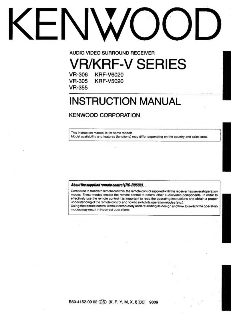
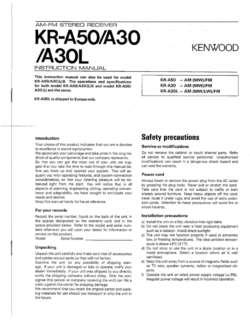
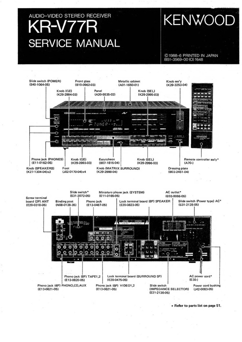
  9. Kenwood KR-V55R User manual

Kenwood KR-V55R User manual

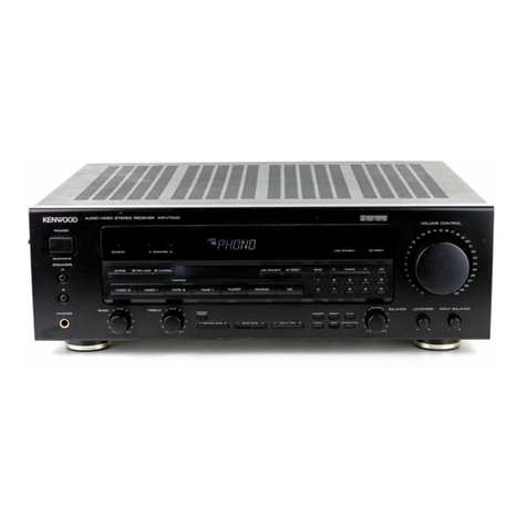
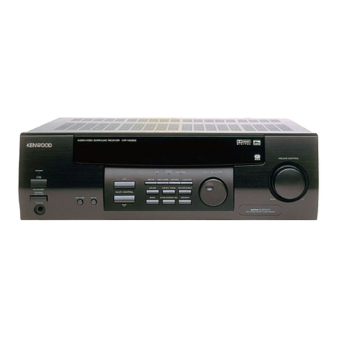
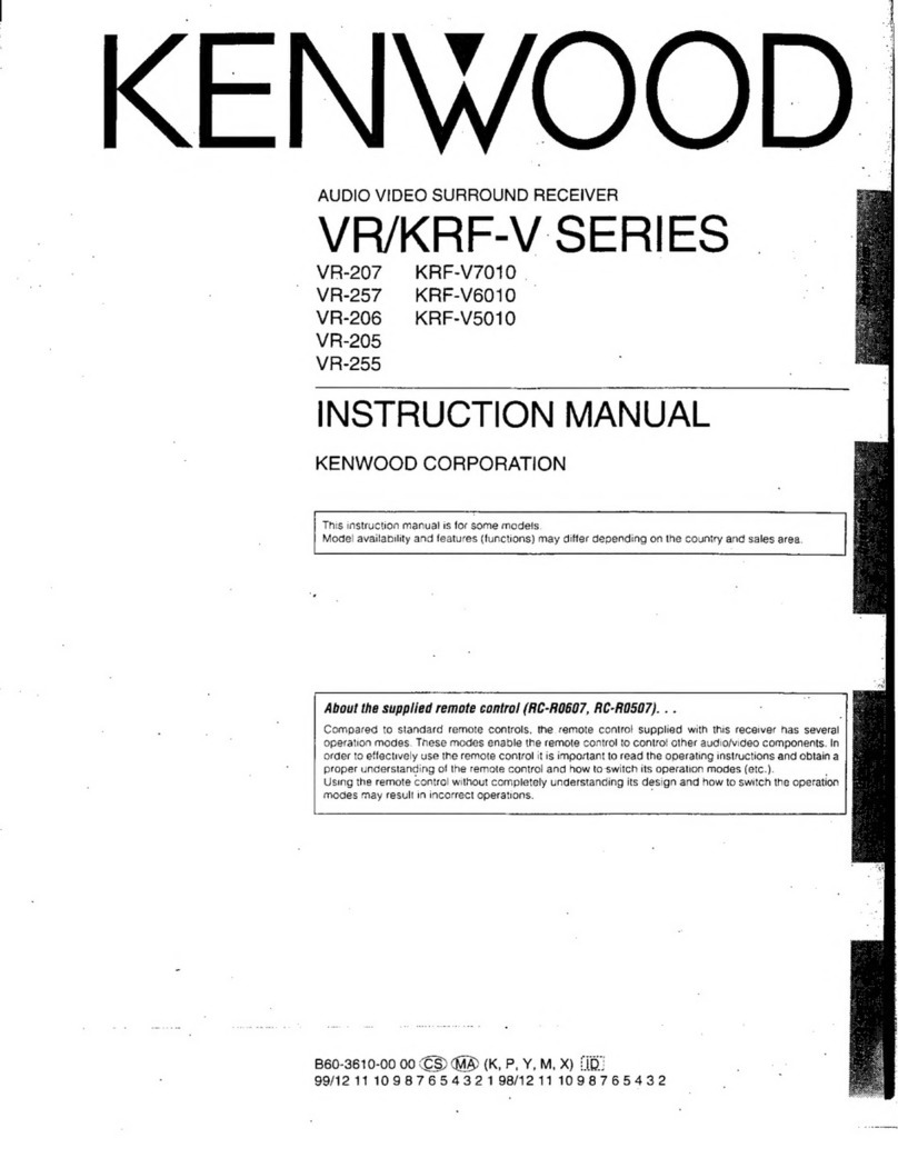
Other Kenwood Stereo Receiver manuals
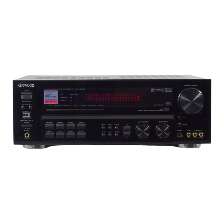
Kenwood KRF-V7020D User manual

Kenwood

Kenwood KRF-V7020D User manual

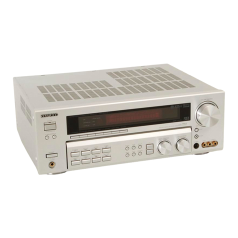
Kenwood krf v5080d User manual

Kenwood

Kenwood krf v5080d User manual

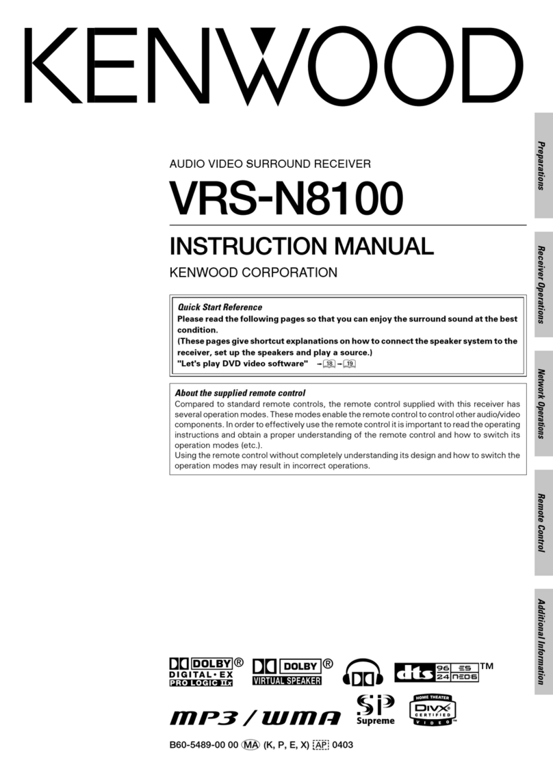
Kenwood VR-707 User manual

Kenwood

Kenwood VR-707 User manual

Kenwood KR-710 User manual

Kenwood

Kenwood KR-710 User manual

Kenwood KRC-578R User manual

Kenwood

Kenwood KRC-578R User manual

Kenwood KRF-V8090D User manual

Kenwood

Kenwood KRF-V8090D User manual

Kenwood 103AR User manual

Kenwood

Kenwood 103AR User manual

Kenwood VR-8060 User manual

Kenwood

Kenwood VR-8060 User manual

Kenwood KRF-V4070D User manual

Kenwood

Kenwood KRF-V4070D User manual

Kenwood KR-A4030 User manual

Kenwood

Kenwood KR-A4030 User manual

Kenwood DVR-605 User manual

Kenwood

Kenwood DVR-605 User manual

Kenwood KRF-V7070D User manual

Kenwood

Kenwood KRF-V7070D User manual

Kenwood KRF-V8010D User manual

Kenwood

Kenwood KRF-V8010D User manual

Kenwood KRF-V7060D User manual

Kenwood

Kenwood KRF-V7060D User manual

Kenwood KR-V6040 User manual

Kenwood

Kenwood KR-V6040 User manual

Kenwood KR-200HT User manual

Kenwood

Kenwood KR-200HT User manual

Kenwood KRF-V8070D User manual

Kenwood

Kenwood KRF-V8070D User manual

Kenwood KR-300HT User manual

Kenwood

Kenwood KR-300HT User manual

Kenwood KR-A4010 User manual

Kenwood

Kenwood KR-A4010 User manual

Kenwood VRS-6100 User manual

Kenwood

Kenwood VRS-6100 User manual

Kenwood C-V351 User manual

Kenwood

Kenwood C-V351 User manual

Kenwood KRF-V8060D User manual

Kenwood

Kenwood KRF-V8060D User manual
Kenwood KR-A3060 User manual

Kenwood

Kenwood KR-A3060 User manual

Kenwood KR-A5520 User manual

Kenwood

Kenwood KR-A5520 User manual

Popular Stereo Receiver manuals by other brands

Teac AG-680 Service manual

Teac

Teac AG-680 Service manual

Teac AGV1050 owner's manual

Teac

Teac AGV1050 owner's manual

Sony STR-435 operating instructions

Sony

Sony STR-435 operating instructions

Pioneer Elite SC-68 Service manual

Pioneer

Pioneer Elite SC-68 Service manual

Pioneer SX-1250 operating instructions

Pioneer

Pioneer SX-1250 operating instructions

Marantz CINEMA 70S owner's manual

Marantz

Marantz CINEMA 70S owner's manual

Yamaha RX-830 owner's manual

Yamaha

Yamaha RX-830 owner's manual

Pioneer AVH-Z7250BT owner's manual

Pioneer

Pioneer AVH-Z7250BT owner's manual

Denon AVR-1311 owner's manual

Denon

Denon AVR-1311 owner's manual

Denon AVR-S760H owner's manual

Denon

Denon AVR-S760H owner's manual

Denon AVR-X7200W Service manual

Denon

Denon AVR-X7200W Service manual

Sony XAV-1500 operating instructions

Sony

Sony XAV-1500 operating instructions

Radio Shack DX-399 owner's manual

Radio Shack

Radio Shack DX-399 owner's manual

Sony STR-DE535 - Fm Stereo/fm-am Receiver operating instructions

Sony

Sony STR-DE535 - Fm Stereo/fm-am Receiver operating instructions

Pioneer SX-1000TA operating instructions

Pioneer

Pioneer SX-1000TA operating instructions

Yamaha MusicCast TSR-5B3D owner's manual

Yamaha

Yamaha MusicCast TSR-5B3D owner's manual

Sony STR-DG500 - Multi Channel Av Receiver Service manual

Sony

Sony STR-DG500 - Multi Channel Av Receiver Service manual

Sherwood Newcastle RX-770 operating instructions

Sherwood

Sherwood Newcastle RX-770 operating instructions

manuals.online logo
manuals.online logoBrands
  • About & Mission
  • Contact us
  • Privacy Policy
  • Terms and Conditions

Copyright 2025 Manuals.Online. All Rights Reserved.

KR-V55R
KE
N
Wi@)
‘e)
DB
KENWOOD
CORPORATION
SERVICE
MANUAL
©1986-6
PRINTED
IN
JAPAN
B51-3002-00(B)2111
Knob
ass’y
(Button)
Panel
{K29-2001-04)
(A20-4844-02)
Knob
(Button)
Potentiometer
/
Metallic
cabinet
(K29-2423-04)
(R29-5010-05)
{A01-1488-01)
KENWOOD
sbencrn
CONTen,
are
ainots
Ganialier
Heny
Knob
(Button)
Knob
(Button)
;
(A70-0144-05)
{K29-2425-04)
x2
(K27-1647-04)
x2
Knob
(Button)
Knob
(Button)
Knob
(Button)
(K27-1264-04)
x2
(K29-2422-04)
(K29-2422-04)
x2
Antenna
holder
Phono
jack(2P)
©
=
AC
outlet*
Power
cord
bushing
AC
power
cord*
(J19-0626-12)
(E13-0227-05)
x3
{E03-)
(U42-0083-05)
{E30-)
Binding
post
(GND)
(NO8-0128-35)
Slide
switch
($31-2113-05)
Phono
jack
(2P)
Phono
jack
(1P)
Lock
terminal
board
(E13-0229-05)
(E13-0126-05)
{E20-0823-05)
Screw
terminal
board
Phono
jack
(8P)
iniphone
jack
(E20-0452-05)
(E13-0814-05)
x3
{E11-0164-05)
Miniphone
jack
(E11-0152-05)
*
Refer
to
parts
list
on
page
14.
§
DISASSEMBLY
FOR
REPAIR
KR-V55R
|
1
Remove
6
screws
retaining
the
front
pannel
1
|
2
Pull
the
front
pannel
toward
to
arrow
direction
3
Remove
screw
retaing
the
sub-pannel
4
Remove
the
sub-pannel
from
hooks
carefully
4)
any
|
*'e
©
©
238
¥3435N8
ZMOA
YSSA-Ny
yOLd
VOY
dV
934
NI
1no
434ine
O
{HDA
4
0
0
;
raga)
334
Ozaavt
338
O
adv
(01
-01e2-60x
}
2310W,
(SPS°91
NIV)
GRY
suo
u34ana
K)
a
eases
(4921691)
BWNT10A
o3uais
v
DIN0¥L9373
O113HLNAS
13S-Y3xVadS
IO
(€€S
OSIE-SOX)
of
vol
o3y
aw
2aDA
434ana
oS
®
S3NOHd
=
|
|
\y--—*——
9.
-
310
[aero
ae
NP9IGIL
NESIGDL
WNOIS
-o10ny
se~ico
és
alle
O
whava
>
Ede
oPnin
238
dw
habe
=
280
a
ene
O
enon
[2
avg
350
I
EDA
Ee
Tousnos
9s'ps0
O
ieee
er
AVId
nee
[i=
wean
O
Sav
id
aa
ZUdA
|
|
|
|
|
rae
|
|
|
9'so
r=)
nat
(eearaa
EEE
liiraaae
O
mwreo
|
189A
TAS
-LNANI
lol
|
|
lolol
we
106
a
rr
ea
aE
pores
~O
ome
rE)
YOLINON
ya4ina
-
|
m
Z
e
WNOIS
+
3UNLIId
£90
SISlS
|
|
|”
|
|
!
=)
ile
a
bil
wal
=
Oe
ee
ce
UE
Hy
roe
Sa
pe
Lh
|
[lj
cama
et
YY
Ht
pI
tf
i
a
Ae
ae
Be
aS
|
F
I
(01
-0si¢
-
Sox)
ee
|
|
|
|
k3
(3dA1
an'n)
SEEE
oS
;
3AIuG
He
g
coven
oe
ae
bee
—
i
|
|
|
tris
NMOG/an
WEY
©)O
2
il
|
K-35
n
(oZbnv)
(s9z1¥7)
$0-6690-20M
|
F
=
se
TV
O
5
XdW
a
ae
ON3~1NOUS
|
|
L_
sam
707NO
LAW
2
eat
Tain
Se
OF
&)
|
Paanenen
asna
7
1103
ONOW/03431S
peeioer
7
tIS-Ofe2-60X)
7
ane
e'21
IN
.
inv
KR-V55R
4
CIRCUIT
DESCRIPTION
Description
of
components.
AUDIO
UNIT
(X09-2310-10)}
|__
Components
_|
Application/Function
Operation/Condition/Compatibility
IC1
Phono
EQ
AMP
MM
cartridge
Input
selecting
selector
Phono/CD/TAPE1/TAPE2
Input
selecting
selector
audio
sig.
of
VIDEO
1/2/3
Electronic
Volume
IC5
Buffer
AMP
(Voltage
gain:
16
dB)
1C7,8
‘
Graphic
EQ.
5
freq.
points
Synthetic
Stereo
Buffer
AMP/3
stage
B.P-F.
Picture
sig.
selecting
VIDEO
1/2/3
Buffer
AMP
(audio
sig.)
VIDEO
1/2
(emitter
follower)
Audio
sig.
mute
1
(TAPE
REC)
MUTE-ON
at
047
ON.
Q7,8
Audio
sig.
mute
2
(Electronic
VOL
out)
MUTE-ON
at
Q9
ON.
ag,
10
Audio
sig.
mute
contro!
of
07,8
Q11~14
Power
AMP
(1st
diff
AMP)
Q23~26
Power
AMN
(driver
stage)
Q27~30
Power
AM
(Final
stage)
Q31~33
Current
limitter
Q15~18
Power
AMP
(2nd
diff
AMP)
Q19,
20
Power
AMP
(Current
mirror
configuration
in
A-class
stage)
Q21,
22
Power
AMP
(Bias)
Q31
(032)
detects
terminal
voltage
of
emitter
resistor
CP1
(CP2).
When
SP
terminal
is
shorted
to
ground,
Q31
(Q32)
becomes
to
ON
and
033
goes
to
ON.
So
that
regurator
circuit
(034,
35)
does
not
function.
|
034,35
Power
supply
to
1st
stage
of
Power
AMP
Q35
works
as
ripple
filter
when
Q34
is
OFF.
|
asses
Re-set
of
IC
11
(—picture
sig.
selecting)
Q36
cuts
VIDEO
3
selecting
signal
to
ICll,
when
POWER
SW
is
ON/OFF.
Q37
;
—30
V
AVR
Display
Q38~40
+14
V
AVR
—14VAVR
POWER
ON
POWER
OFF
+5
V
AVR
(for
microprocessor)
store
sig.
control
(IC2,
3)
_
data
sig.
control
(IC2,
3)
clock
sig.
control
(IC2,
3)
store
sig.
control
(IC4)
store
sig.
control
(IC
4)
—
oe
i
aa
a
———.----—
Q57~-59
Relay
(KI)
control
+5
VAVR
Fip
[Status
|_aso
|
a6
|
as2
Power
ON
|
on
|
off
__|
working
|
Power
ofr
|
off
|
on
|
of
|
Buffer
AMP
(picture
sig.
output)
VIDEO
1
(emitter
follower)
VIDEO
2
(emitter
follower)
pe
Monitor
out
emitter
follower
Q66,
67
;
Control
of
picture
sig.
selecting
\
CIRCUIT
DESCRIPTION
TUNER,
p-COM
UNIT
(XO5-3150-10)
Application/Function
Operation/Condition/Compatibility
FM
IF/DET,
AM
MIX/iF/DET
FM
MPX
PLL
synthe
Microprocessor
Components
system
control
Microprocessor
remote
control
FIP
driver
Frequency
display
control
FM
IF
AMP
TUNE
indicating
signal
(transistor
array)
conv.
to
display
frequency
(static
display)
AM/FM
switching
Prevention
of
wrong
STEREO
indicating
Buffer
AMP
Ripple
filter
|
oe
|
FM
Bewitching
|
oeto
|
kerinpteythe
OT
CO™—OCOC‘C‘*C
[|__
a2
|
Pater
TERE)
|
working
when
STEREO
indicatorightson
CS
Q5 ON
when
FM
TUNE
indicator
lights
on.
(emitter
follower)
KR-V55R
ADJUSTMENT
INPUT
OUTPUT
TUNER
ALIGNMENT
No.
ITEM
SETTINGS
SETTINGS
SETTINGS
POINTS
ALIGN
FOR
FIG,
FM
SECTION
Unless
otherwise
specified,
the
individual
switches
should
be
set
as
following:
SELECTOR:
FM
MODES
STEREO
(A)
DISCRIMINATOR
(1)
98,
OMHz
lkHz,#75kHz
dev
6OdB(ANT
input)
(A)
98.
OMH2
1kHz,+75kHz
dev
60dB(ANT
input)
Connect
a
DC
voltmeter
MONO
(X05-
ie)
between
TP8
and
TPS,
98,
OMHz
MONO
(X05-3150)
98,
OMHz
T3
Repeat
alignments
1
and
2
several!
times.
Connect
a
330k
resis-
DISCRIMINATOR
(2)
Minimum
distortion.
(A)
tor
to
TP7,
Connect
(X05-3150)
98,
OMHz
a
frequency
counter
98,
OMHz
VR3
76,
OOkH2
0
dev
to
the
resistor
via
B0dB(ANT
input)
an
AC
voltmeter,
(C)
98,
OMHz
(X05-3150)
4
DISTORTION
1kHz,#68.25kHz
dev
(B)
98.
OMHz
Front
end
Minimum
distortion,
(STEREO)
Selector3L
or
R
IFT
Pilot?
#6,.75kHz
dev
60dB(ANT
input)
(C)
98.
OMH2
ikHz
+68.
25kHz
dev
Selector:L
or
R
Minimums
crosstalk.
A
compromise
adjustment
may
be
required
if
left-to-
Pilot:
26.75kHz2
dev
right
and
right-to-left
6OdB(ANT
input)
separations
are
unequal,
AM
SECTION
Keep
the
loop
antenna
installed.
INPUT
SELECTOR:
AM
(1)
Connect
a
DC
voltmeter
530kHz
Pee
we
eee
wom
|
ame
ee
as
-
(2)
|
BAND
EDGE
Connect
a
DC
voltmeter
|
1610kHz
(05-3150)
|
ee
(2)
to
TP2,
(1602kHz)
TC1
8,0¥
Repeat
alignments
(1)
and
(2)
several
times.
(D)
Maxinus
auplitude
and
RF
ALIGNMENT
600(603)kHz
(B)
600kHz
(X05-3150)
symmetry
of
the
(1)
fot
ee
mod
.
(603kHz)
L2
oscilloscope
display.
Maximum
amplitude
and
SEPARATION
(B)
98,
OMHz
(X05-3150)
VR4
RF
ALIGNMENT
agian
(B)
1400kHz
(X05-3150)
symmetry
of
the
(2)
400Hz»30%
mod
(1404kHz)
TC2
oscilloscope
display.
Repeat
alignments
(3)
and
(4)
several
times,
(D)
Maximue
amplitude
and
(5)
|
IF
TRANSFORMER
1000(999)kHz
(B)
1000kHz
(X05-3150)
symmetry
of
the
400Hz,30%
mod
(999kHz)
Ti
oscilloscope
display.
AM/FM
COMMON
SECTION
(A)
TUNE
INDICATOR
98,
OMHz
FM
reception
|
(X05-3150)
THRESHOLD
LEVEL
0
dev
98.
OMHz
VR2
Light
18dB(ANT
input)
(D)
(6)
|
TUNE
INDICATOR
1000(999)
kHz
THRESHOLD
LEVEL!
20
~
24dB(ANT
input)
AM
reception
|
(X05-3150)
:
1000(999)kHz
VRi
Light
AUDIO
SECTION
(E)
(X09-2310)
CP1(CP2)
VR2
(R)
KR-V55R
REGLAGE
DE
REGLAGE
DU
POINT
DE
eres
LA
SORTIE
TUNER
L*
ALIGNEMENT
ALIGNER
POUR
FIG,
SECTION
MF
Sauf
en
cas
d’indications
spéciales,
régler
chaque
commutateur
comme
suits
SELECTEUR
DES
ENTRESS:
MF
_MODE3
STEREO
(A)
DISCRIMINATEUR
98,
OMHz
Relier
un
voltmétre
MONO
(X05-3150)
(1)
1kHz.#75kHz
déy
CC
entre
les
98,
OMHz
T2
6OdB(Entrée
ANT)
TP8
et
TP9,
(A)
98,
OMH2
”
LkHz,
#75kH2
60dB(
Entrée
DISCRIMINATEUR
(2)
Distorsion
minimnale,
MONO
(X05-3150)
(B)
98,
OMH2
T3
__Répéter
Jes
points
1
et
2
plusieurs
fois,
Relier
une
résistance
OSCILLATEUR
(A)
de
330kQ2
&
TP7,
3
CONTROLE
PAR
98,
OMHz
Raccorder
un
compteur
LA
TENSION
0
dév
de
fréquence
a
une
76,
00kH2
60dB(
Entrée
résistance
par
l*intérmediaire
d'un
voltmétre
CA,
(C)
98,
OMHz
DISTORSION
1kHz,#68,25kHz2
dév
(X05-3150)
(STEREO)
Selection3L
ou
R
{B)
98,
OMHz
Téte
HLF.
Distorsion
minimale,
Signal
pilote:
IFT
#6,75kHz
dév
60dB(Entrée
ANT)
(C)
98,
0MHz
1kHz,#68,25kHz
dév
(X05~-3150)
(B)
98,
OMHz
VR4
Signal
pilote?
60dB(Entrée
ANT)
SelectionsL
ou
R
26,
75kHz
dév
SECTION
MA
Laisser
I|'antenne
bouche
MA
installée,
|
SELECTEUR?
AM
(1)
|
BORD
DE
BANDE
Relier
un
voltwétre
530kHz
(X05-8150)
a
(1)
CC
au
TP2,
(581kHz)
L3
1,5V
(2)
|
BORD
DE
BANDE
Relier
un
voltmetre
1610kHz
(X05-3150)
|
(2)
CC
au
TP2,
(1602kHz)
TCL
8,0V
Répéter
les
points
(1)
et
(2)
plusieurs
fois,
(D)
Amplitude
et
symétrie
(3)
|
ALIGNEMENT
H.T.|.
600(603)kHz
maximale
de
|'affichage
de
(1)
400Hz.30%
mod
(603kHz)
L2
l’oscilloscope.
(D)
.
(B)
Diaphonie
minimale.
Un
compromis
de
réglage
peut
étre
nécessaire
si
les
séparation
de
gauche
a
droite
et
droite
a
gauche
sont
inéglage.
SEPARATION
Amplitude
et
symétrie
1400kHz
(X05-3150)
maximale
de
l’affichage
de
(1404kHz)
TC2
loscilloscope.
Répéter
les
points
(3)
et
(4)
plusieurs
fois,
(D)
Awplitude
et
symétrie
(5)
|
TRANSFORMATEUR
1000(999)
kHz
(B)
1000kHz
(X05-3150)
waximale
de
|’affichage
de
F.I,
400H2.30%
mod
(999kHz)
Ti
1*oscilloscope.
SECTION
COMMUNE
MA/MF
1400(1404)kHz
(4)
|
ALIGNEMENT
4.7.
(2)
400Hz.30%
mod
(X05-3150)
VR2
Arrume
INDICATEUR
DE
SYNTONISATION
Reception
MF
98,
OMHz
INDICATEUR
DE
SYNTONISATION
NIVEAU
DE
SEUIL
Reception
MA
{
(X05-3150)
1000(999)kHz
SECTION
AUDIO
COURANA
DE
POLARISATION
(X09-2310)
VR1
(G)
VR2
(D)
Connecter
un
voltmétre
CC
CP1(CP2)
KR-V55R
|
ABGLEICH
Fim,
|
cecrstwo
|
ersten
|
emsrouuine
—[ensretiwme
|
‘vowse
|
ascercu
ron
[np
GEGENSTAND
EINSTELLUNG
EINSTELLUNG EINSTELLUNG
PUNKTE
ABGLEICHEN
FUR
ABB,
UKW-EMPFANGSABTEILUNG
AuBer
wenn
anders
angegeben:
die
verschiedenen
Schalter
wie
folgt
einstellen:
EINGANGSUMSCHALTER:
FM
(A)
98,
OMHz
1kHz,+#75kH2
Hub
60dB(
ANT-Eingang)
(A)
98,
OMHz
1kHz,+75kz
Hub
S0dB(ANT-Eingang)
DISKRIMINATOR
(1)
MONO
messer
zwischen
TP8
98,
OMHz
T
und
TP9
anschlieBen,
2
MONO
(X05-3150)
(B)
98,
OMHz
13
Abstimmungen
1
und
2
mehrere
Male
wiederholen,
Einen
330k2
Wider-
Einen
Gleichspannungs-
(X05-3150)
DISKRIMINATOR
(2)
Miniwa!l
Klirrfaktor,
-
(A)
standen
zu
TP7
SPANNUNGS-
98,
OMHz
assch]ieBen,
Einen
(X05-3150)
3
GEREGELTER
0
Hub
Frequenzzahler
uber
98,
OMHz
VRB
76,
00kHz
OSZILLATOR
60dB(ANT-Eingang)
|
einen
Wechse!
spannungs
messer
an
den
Wider-
stand
anschl
ieBen.
(C)
98,
OMHz
1kHz,
£68,
25kHz
Hub
Wahler3L
oder
R
Pilotten’
#6,
75kHz
Hub
60dB(
ANT-Eingang)
(C)
98,
OMHz
IkHz,#68,25kH2
Hub
WahlersL
oder
R
Pilotten?
(X05-3150)
Frontende
IFT
KLIRRFAKTOR
(STEREO)
98,
OMHz
Miniwal
Klirrfaktor,
Minimales
Ubersprechen,
STEREO
KANAL
TRENNUNG
(X05-3150)
VR4
Eine
Ausgleichrege
lung
kann
notwendig
seins
falls
links-zu-rechts
und
+6,
75kHz
Hub
rechts-zu-]
inks.
60dB(
ANT-Ei
ngang)
Trennungen
ungleich
sind.
MW-EMPFANGSABTEILUNG
Die
M¥-Rahmenantenne
angebracht
lassen.
WAHLER:
AM
(1)
BANDKANTE
messer
zu
TP2
530kHz
(X05-3150)
1,5V
(1)
anschlieBen,
(531kH2)
L3
‘
Einen
Gleichspannungs-
.
(2)
BANDKANTE
-
messer
zu
TP2
1610kHz
(X05-3150)
(2)
;
anschl
ieBen,
(1602kHz)
TC1
Abstimmungen
(1)
und
(2)
wehrere
Male
wiederholen,
(D)
(3)
|
HF-ABGLEICH
600(
603)
kHz
600kHz
(X05-3150)
und
Syesetrie
des
400Hz.30%
mod
(603kiiz)
L2
0szilloskopbi
ides.
(D)
Maximal
Amplitude
(4)
|
HF-ABGLEICH
1400(1404)
kHz
(B)
1400kHz
(X05-3150)
und
Symmetrie
des
(2)
400H2.30%
mod
;
(1404kHz)
TC2
0szilloskopbildes.
Abstimmungen
(3)
und
(4}
mehrere
Male
wiederholen,
-
(D)
Maximal
Amplitude
(5)
|
ZF-UBERTRAGER
1000(999)kHz
(B)
1000kHz
(X05-3150)
/
und
Symmetrie
des
400Hz.30%
mod
(999)
kHz
Tl
0szilloskopbildes.
MW/UKW-EMPFANGSABTEILUNG
Die
MW/UKW-Rahmenantenne
angebracht
lassen,
WAHLERS
AM/FM
98,
OMHz
Maximal
Amplitude
(A)
98,
0MHz
0
Hub
18dB(ANT-Eingang)
UKW-emptang
|
(X05-3150)
98,
ONH2
VR2
(X05-3150)
YR1
Einschalen
.
(X09-2310)
Volume:
0
VR1
(L)
18aV
VR2
.(R)
ABSTIMNANZEIGE
SCHWELLENPEGEL
Einschalen
(D)
1000(999
kHz
Mi-emptang
1000(999)kHz
(6)
|
ABSTIMMANZEIGE
Einen
Gleichspan-
nungsmesser
tiber
cP1(CP2)
o3yu3SLS
QILBHLNAS|
[BGOW
Ws]
—
[SSNOHd]
KR
-VS55R
FRONT
Refer
to
the
schematic
diagram
for
the
values
of
resistors
and
capacitors.
jo
ce
<
©
co
©
ou.
=
2
>
oD
3
Oe
2
cS
3)
om
Q
Q
E
°
oO
o
S
<¢
3
ry
1o)
-
oO
a
o
ie}
Bas
°
a 2
<
Is
LO)
LC)
an
ag
<
OC
Te)
LC)
7
oC
<
Lg
bse!
eau!
Uegeid
|Meesoin
c—
|
|
|
|
(SYsNVadS
|
ANwatv
<
>
(3YOW
19
U8)
|
(ug
M0138)8'V
a‘v
[te
cee
Se
ae
ae
oh
aca
pe
a
set
eee
ees
<earteniyranacrtonintnaritg
niacin
annem
tne
matinee
jbatniaram
tment
ecnntemlts
Nt
eet
INN
erate
<henstrtpnctneytanoienantocestimenin
taunt
tthanenttinanen
nti
en
ihatiian
ntmnibtiaat
tants
oss
mnie
nel
rasmenretinuunnesinraines
nema
oineamtsantinaaiginnnsinsin
owes
ani
laa
a
ie
tt
fe
res
nnn
eae
nan
i
i
a
ai
gras
shar
ene
wend
cadens
each
FKR-V55R_KR-V55R
|
PC
BOARD
300Hz
3kz
63Hz
=
IkHz
1OkHz
a
Refer
to
the
schematic
diagram
for
the
values
of
resistors
and
capacitors.
X13-5540-10
KR-V55R