manuals.online logo
Brands
  1. Home
  2. •
  3. Brands
  4. •
  5. Kenwood
  6. •
  7. Stereo Receiver
  8. •
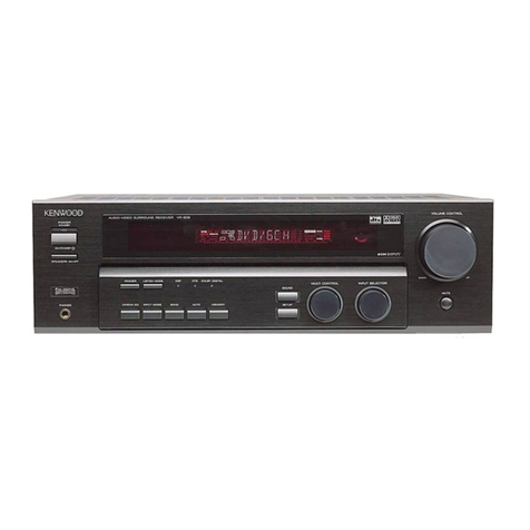
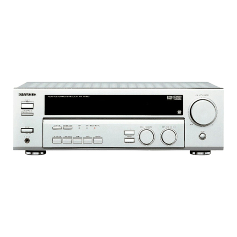
  9. Kenwood KR-200HT User manual

Kenwood KR-200HT User manual

KENWOOD
AUDIO
VIDEO
SURROUND
RECEIVER
KR-200HT
INSTRUCTION
MANUAL
KENWOOD
CORPORATION
This
manual
contains
instructions
for
two
models.
Model
availability
and
features
|
(functions)
may
differ
depending
on
country
and
sales
area.
|
98/12
1t
10987654321
971211
109
Before
applying
power
Before
applying
power
|»
caution:
Read
mis
se
KA-200HT
{En/K]
e
safe
operation.
Unit
are
designed
for
operation
as
follows.
U.S.A.
and
Canada
.-
AC126
V
only
Europe
and
U.K.
......cecceccecsccccesseseetssceensasessenes
AC
230
V
only
Australia
.
AE
240
V
only
China
and
Russia
AC
226
V
only
“Other
countries.
AC
110-120/220-240
V
switchable
*AC
voltage
selection
AC
voltage
selector
switch
The
AC
voltage
selector
switch
on
the
rear
panel
is
set
to
the
voltage
ON
eaoy
that
prevails
in
the
area
to
which
the
unit
is
shipped.
Before
connecting
men
|
the
power
cord
to
your
AC
outlet,
make
sure
that
the
setting
position
=I)
of
this
switch
matches
your
line
voltage.
If
not,
it
must
be
set
to
your
voltage
in
accordance
with
the
following
direction
L_»
Note
Our
warranty
does
not
cover
damage
caused
by
excessive
line
voltage
due
to
improper
setung
of
the
AC
voltage
selector
switch
Move
switch
lever
to
match
your
line
vaitage
with
a
small
screwdriver
or
other
pointed
tool.
Safety
precautions
WARNING:
TO
PREVENT
FIRE
OR
ELECTRIC
SHOCK,
DO
NOT
EXPOSE
THIS
APPLIANCE
TO
RAIN
OR
MOISTURE.
CAUTION
RISK
OF
ELECTRIC
SHOCK
:
DO
NOT
OPEN
:
Read
this
section
carefully
fo
ensure
Sate
operation.
A
Nacat
cay
CAUTION:
TO
REDUCE
THE
RISK
OF
ELECTRIC
SHOCK,
DO
NOT
REMOVE
COVER
(OR
BACK).
NO
USER-SERVICEABLE
PARTS
INSIDE,
REFER
SERVICING
TO
QUALI-
FIED
SERVICE
PERSONNEL
THE
LIGHTNING
FLASH
WITH
ARROWHEAD
SYMBOL,
WITHIN
AN
EQUILATERAL
TRIANGLE,
1S
IN-
TENDED
TO
ALERT
THE
USER
TO
THE
PRESENCE
OF
UNINSULATED
“DANGEROUS
VOLTAGE”
WITHIN
THE
PRODUCT'S
ENCLOSURE
THAT
MAY
BE
OF
SUFFICIENT
MAGNITUDE
TO
CONSTITUTE
A
RISK
OF
ELECTRIC
SHOCK
TO
PERSONS
THE
EXCLAMATION
POINT
WITHIN
AN
EQUILATERAL
TRIANGLE
IS
INTENDED
TO
ALERT
THE
USER
TO
THE
PRESENCE
OF
IMPORTANT
OPERATING
AND
MAINTENANCE
(SERVICING)
INSTRUCTIONS
IN
THE
LITERATURE
ACCOMPANYING
THE
APPLIANCE.
Unpacking
Unpack
the
unit
carefully
and
make
Sure
that
all
accessories
are
put
aside
so
they
will
not
be
lost.
Examine
the
unit
for
any
possibility
of
shipping
damage.
If
your
unit
is
damaged
or
fails
to
operate,
notify
your
dealer
immediately.
{f
your
unit
was
shipped
to
you
directly,
notify
the
shipping
company
without
delay
Only
the
consignee
{the
person
or
company
receiving
the
unit)
can
file
a
claim
against
the
carrier
for
shipping
damage.
We
recommend
that
you
retain
the
original
carton
and
packing
materials
for
use
should
you
transport
or
ship
the
unit
in
the
future.
SCEEES
Accessories
FM
indoor
antenna
(1)
AM
loop
antenna
(1)
Loap
antenna
stand
(1)
‘
\
/
Remote
control
unit
{1}
Batteries
(RE/AA)
(2}
.
satel,
KR-2O0HT
(En
/K}
Specialfeatures
DOLBY
PRO
LOGIC
&
DOLBY
3
STERE
The
surround
system
reproduces
video
software
programs
carrying
the
({)[bastexaxc]
mark
with
similar
acoustic
effects
to
movie
theaters.
The
DOLBY
PRO
LOGIC
mode
cantrols
the
audio
signals
of
the
Front
Left/Right,
Center
and
Rear
surround
channels
using
the
built-in
directivity
enhancer
circuit
to
reproduce
the
feeling
of
sound
motions
very
realistically.
The
DOLBY
3STEREO
mode
can
reproduce
the
motions
of
sound
even
when
only
the
front
and
center
speakers
are
used,
by
providing
proper
acoustic
position
using
the
directivity
enhancer
circuit.
SRS
3D
Stereo
The
SRS
(Sound
Retrieval
System)
is
an
innovative
system
simulating
a
3-dimensional
sound
space,
which
features
clearly
improved
feelings
of
depth,
sound
field
extension
and
acoustic
image
positioning
as
well
as
a
widened
listening
area.
Contents
Before
applying
power
AN
Before
applying
power
Ay
Safety
precautions
Special
features
.
System
connection.
Connections
of
Audio
and
Video
components
About
the
system
control
connections
Connections
of
speakers...
Connections
of
antenna...
FM
DE-EMPHASIS/CHANNEL
SPACE
SWitCH
oo...
Controls
and
indicators
Operation
of
remote
control
unit.
Playing
music
Sound
adjustment
functions
3s
8
13
FOCOLIG
.srcevecseenssssnesstneessonstnsesiensssnsoeusnsenessnsennnasnessasenasensessnssennsseeanstanasnanenvntesunesninaniessusneatinasnintetneanietisisuuaniuasssesusesennes
16
Broadcast
Reception
.
17
Receiving
broadcast
stations
...........
.
Receiving
radio
stations
by
specifying
its
frequene|
Staring
radio
stations
in
memory
(Station
preset)...
Receiving
a
preset
Station
oo...
cesses:
Receiving
all
preset
stations
in
order
(PCALL).
Playback
Of
Vid@OtQ@
oo...
cccccccceccsesteccsesseene
Recording
of
video
source
(VIDEO2
-»
VIDEQ1
.
Operation
of
video
components
Presence
play
..
Adjustments
for
surround
pla
Surround
BBY
occ
lee
SRS
3D
Stereo
(Sound
Retrieval
System}
In
case
of
difficulty
..
A.
Specifications
Connections
of
Audio
and
Video
components.
PoE
RNa
OES
Make
connection
as
shown
below.
When
connecting
the
related
system
components,
refer
also
to
the
instruction
manuals
of
the
related
compo-
nents.
,
A
Do
not
plug
in
the
power
lead
until
atl
connections
are
completed.
KR-200HT
[En/K]
oe
Malfunction
of
microcomputer
if
operation
is
not
possible
or
erroneous
display
appears
even
though
all
connections
have been
made
properly,
reset
the
micro-
computer
referring
to
“In
case
of
difficulty”.
26
Video
deck
1,
cassette
deck
1
OUT
or
MD
recorder
=
4
Audio
=|
foo
[-Je}
===)
=s
2]
;
“1
IN
System
control
cord
Video
deck
2
or
DVD/LD
player
*1
The
system
control
cordcan
be
connected
when
a
uso
OUT
on
KENWOOD
audio
compo-
nent
system
is
connected.
Be00
REC]
PLAY
IN
OUT
Shape
of
AC
outlets
U.S.A.,
CANADA
and
China
Australia
Other
countries
/
L—
BE
)
<4
To
wall
AC
outiet
\
Monitor
TV
Video
IN
System
control
cord
Multiple
CD
player
oseR
Pees
Turntable
*2
Do
not
connect
system
control
cord
to
the
cassette
deck
connected
to
the
TAPE
2
MONITOR
jacks.
Caution
regarding
placement
(Except
for
U.S.A.
and
Canada}
To
maintain
proper
ventilation,
be
sure
to
leave
a
space
around
the
unit
(from
the
largest
outer
dimensions
including
projections}
equal
to,
or
greater
than,
shown
below.
Left
andright
panels
:
10cm
Rear
panel
:10em
Top
panel
About
the
system
control
connections
Be
KR-200HT
[En
/K)
system
control
operations.
(SLTIB}
Mode:
for
GLB
terminals
only
EXAMPLE:
[XS8]
mode
connections
The
underlined
portion
represents
the
setting
of
the
system
control
mode.
Multipie
CD
Piayer
System
control
cord
ISL16]
[XS]
[XS8]
[XR}
[SL16]
[xS]
[xs8]
Connecting
system
control
cords
after
connecting
a
KENWOOD
audio
component
system
lets
you
take
advantage
of
convenient
There
are
two
KENWOOD
system
control
modes.
Make
connections
according
to
the
groups
of
terminal
symbols
shown
below.
iXSB
Mode:
lets
you
combine
Xe,
xs),
and
XS
terminals
This
unit
is
compatible
with
both
[XS8]
and
(SL16]
modes.
It
comes
from
the
factory
set
to
the
[SL16]
mode.
To
switch
to
the
(XS8]
mode,
follow
the
instructions
in
“SWITCHING
BETWEEN
[XS8]
AND
[SL16)”
below.
Some
CD
players
and
cassette
decks
are
not
compatible
with
the
[SL16]
sy:
making
system
connections
with
equipment
that
is
not
{SL16]
compatible
i
@Some
MD
players
are not
system
control
compatible.
You
cannat
make
system
control
connections
to
this
kind
of
equipment.
EXAMPLE:
[SL16}
mode
connections
The
underlined
portion
represents
the
setting
of
the
system
control
mode.
Turntable
[SL16]
[XS8]
System
IsL16)
conta
cord
Multiple
CD
Player
‘stem
control
mode.
Be
sure
to
use
the
[XS8]
system
control
mode
when
[$L16]
[XS]
[X$8]
[XR]
(SL16)
[XS]
[xS8)
Qorgs
cause
a
malfunction
and
darnage
your
equipment
1.
[SL16}
equipment
cannot
be
combined
with
[XRI,
{XS},
and
[XS8]
equipment
for
system
operations.
If
your
equipment
consists
of
this
kind
of
combination,
please
do
not
connect
any
system
contro!
cords.
Even
without
system
controi
cords,
norma
operations
can
be
carried
out
without
affecting
performance
2.
Donot
connect
system
control
cords
to
any
components
other
than
those
specified
by
KENWOOD.
It
may
3.
Be
sure
the
system
control
plugs
are
inserted
all
the
way
in
to
the
system
control
terminals
a’
“saa
_
ABOUT
THE
SYSTEM
CONTROL
OPERATIONS
Remote
Control
(possible
when
the
system
control
mode
i
matches).
Lets
you
operate
source
components
with
the
system
remote
supplied
with
this
unit.
Automatic
Operation
(Except
[XR]
equipment)
When
you
start
playback
from
a
source
component,
the
input
selector
on
this
unit
switches
to
that
component
automatically.
(Except
TAPE
2)
:
Synchronized
Recording
(Except
[XR]
equipment)
Lets
you
synchronize
recording
with
the
start
of
playback
when
recording
from
CD,
MD.
SWITCHING
BETWEEN
[XS8]
AND
[SL16]
The
system
contro!
mode
can
be
switched
over
easily
with
the
following
operation.
@
Unpiug
the
AC
power
cord
from
the
wall
outlet
@
Set
the
SYSTEM
CONTROL
switch
on
the
tear
panel
to
the
desired
position
©
Onna
(SB)
GL)
@
This
operation
does
not
affect
the
items
stored
in
memory.
1.
Connect
all
cords
firmly.
lf
connections
are
loose,
there
could
be
loss
of
sound
or
noise
produced.
2.
When
plugging
and
unplugging
connection
cords,
be
sure
to
first
remove
the
Power
cord
from
the
AC
outlet.
Plugging/
unplugging
connection
Notgs)
cords
without
removal
of
the
power
cord
can
cause
malfunctions
or
damage
to
the
unit
3.
Do
not
connect
up
a
power
source
which
is
larger
than
that
indicated
on
the
socket
at
the
rear
of
the
unit
4,
If
the
system
control
cords
or
audio
cords
are
not
connected
properly,
the
remote
control
or
automatic
operation
between
system
components
will
not
work
properly
KR-200HT
[En/K)
Powered
Center
speaker
Speaker
system
sub-woofer
(8Q
~
160}
(8Q
~
16Q)
R
L
re)
war
@
Push
lever.
l
~~
*
@
Insert
cord.
R
L
Surround
speakers
{4Q
~
BQ)
@
Never
short-circuit
the
+
and
-
speaker
cords.
For
the
symptom
and
remedy
when
a
speaker
cord
is
shorted.
-3e
@f
the
left
and
right
speakers
are
connected
inversely
or
if
the
speaker
cords
are
connected
with
reversed
polarity,
the
sound
becomes
unnatural
with
ambiguous
acoustic
image
positioning.
Be
sure
to
connect
the
speakers
and
speaker
cords
correctly.
Connect
a
sub
woofer
it
you
want
to
enhance
the
bass
sound.
The
connected
sub-woofer
should
be
a
power
sub-woofer
with
a
builtin
amp.
Connection
of
antenna.
|
Connection
method
to
each
antenna
terminal
KF-200HT
[En/K]
i
@
Push
lever.
@
Insert
cord.
©
Return
lever.
if
:
a
!
rl
el
wa
Sy
Le
|
)
{
_
:
1
J]
wy:
AM
loop
antenna
connection
The
supplied
antennas
for
indoor
use.
Place
it
as
far
as
possible
from
the
main
system,
TV
set,
speaker
cords
and
power
cord,
and
set
it
to
a
direction
which
provides
the
best
reception
i
ANTENNA
aM
iy
:
—F
—
&d
x
!
L
»
rr
(Eg
|
a
FM
indoor
antenna
connection
FM
outdoor
antenna
connection
The
accessory
antenna
is
tor
temporary
indoor
use
only:
For
stable
signal
reception
we
recommend
using
an
outdoor
antenna.
Remove
the
indoor
antenna
if
you
connect
one
outdoors
Lead
the
75
Q
coaxial
cable
connected
to
the
FM
outdoor
antenna
into
the
room
and
connect
it
to
the
FM
75
&2
terminal
Pull
out
while
rotating
ANTENNA
When
using
a
commercially-available
T-shaped
indoor
antenna
(300
),
connect
it
to
these
terminals
(Remove
the
provided
indoor
antenna
if
you
connect
a
T-shaped
indoor
antenna,}
=
KR-200HT
(En/K?
FM
DE-EMPHASIS
/
CHANNEL
SPACE
switch
(Except
for
U.S.A.
and
Canada}
The
FM
DE-EMPHASIS
/
CHANNEL
SPACE
switch
on
the
rear
panel
is
set
to
the
correct
setting
that
prevails
in
the
area
to
which
the
unit
is
shipped.
However,
if
the
FM
DE-EMPHASIS
/
CHANNEL
SPACE
setting
is
not
matched
to
the
area
where
the
unit
1s
to
be
used;
for
instance,
when
you
moved
from
area
1
to
area
2
or
vice
versa,
desired
reception
of
AM/FM
broadcasts
is
not
expected.
In
this
case,
change
the
FM
DE-
EMPHASIS
/
CHANNEL
SPACE
setting
in
accordance
with
the
area
corresponding
to
the
table.
The
FM
DE-EMPHASIS
is
switched
over
at
the
same
time
e@When
changing
the
setting
of
the
FM
DE-EMPHASIS
/
CHANNEL
SPACE
switch,
first
disconnect
the
power
cord
of
the
amplifier,
then
reset
the
channel
space
switch,
connect
the
power
cord
again,
and
turn
the
power
on
a
75ys
AM
10kHz
=
FM
100kH2
Area
CHANNEL
SPACE
freq.
FM
DE-
EMPHASIS
U.S.A.,
Canada,
Hawaii,
South
American
countries
FM:
100kHz
AM:
10kHz
75
ps
N
Other
countries
FM:
50kHz
AM:
9kHz
50
ys
SURROUND
Indicator
3
STEREO
indicator
KR-2O0HT
(En/k)
MEMORY
ind:cator
TAPE
2
indicator
H
NB.
circuit
Source
Cnrect
af
indicator
1
DIRECT
stereo
reception
indicator
Indicator
;
3.
ST
Broad
ft
—
|
|
AUTO
tuning/AUTO.
indicates
STEREO
Frequency
display
TUNED
incicator
indicator
Input
disolay,
Preset
channel
display,
Surround
mode
display
e
e0
Display
6606
0
KENWOOD
eur
meuscron
@POWER
key
@AUTO
key
@DISPLAY
key
Press
to
switch
the
power
ON
and
OFF
@
STANDBY
indicator
OSRS
3D
indicator
.
Lights
when
the
SRS
3D
system
is
ON
O
SPEAKERS
indicator
:
Lights
when
the
speakers
are
ON
OSTEREO
key
-
24.
Press
to
turn
the
surround
mode
OFF
@DOLBY
PRO
LOGIC
key
ery
@DOLBY
3
STEREO
key
2a,
OSRS
3D
key
~
B,
OINPUT
SELECTOR
knob
Rotate
to
select
the
input
source
@VOLUME
CONTROL
knob
@
PHONES
jack
Plug
headphones
into
this
jack
Press
to
select
the
tuning
mode
from
the
auto
tuning
and
manual
tuning
modes.
+(4Z,
Press
and
hold
the
AUTO
key
for
more
than
2
seconds
to
switch
the
VIDEO1
display
to
another
input
display
:
@®
SPEAKERS
key
Press
to
turn
the
speakers
ON
and
OFF
@
DIRECT
key
-
a
Press
when
tuning
a
broadcast
station
by
entering
the
digits
of
its
frequencies
@
MEMORY
key
+O"
Press
when
registering
a
broadcast
sta-
tion
in
the
preset
memory
@
Numeric
keys
(1
to
0,
+10)
@BAND
key
~Gz
Press
to
switch
the
broadcasting
band
Press
ta
switch
the
displayed
information
between
the
surround
mode
display
and
input
selector
display
Press
and
hold
the
DISPLAY
key
for
more
than
2
seconds
to
switch
the
display
bright-
ness.
@TUNING
keys
(vv,
A}
-Gin
Press
to
select
a
radio
station
@TAPE
2
MONITOR
key
~
6)
Press
to
monitor
the
sound
being
re-
corded,
etc
@N.B.
key
Ga,
Press
to
compensate
for
the
insuffi-
ciency
in
the
base
sound
@P.CALL
keys
(Vv.
A)
-
oR
Press
to
select
one
of
the
preset
sta-
tions
@
SOURCE
DIRECT
key
~84)
Press
to
listen
to
the
source
sound
with
a
higher
sound
quality
About
the
STANDBY
indicator
This
unit
has
@
STANDBY
indicator,
the
lighting
of
which
indicates
that
a
small
amount
of
current
is
supplied
to
back
up
the
internal
memory
of
the
unit.
This
status
1s
referred
to
as
the
standby
mode
of
the
unit.
In
this
mode,
the
power
of
the
unit
can
be
switched
ON
from
the
remote
control
unit
Wikies
tha
and
onan
ha
vead
fara
lana
nanad
at
time
ark
athe
nner
card
fram
the
newer
niitlet
KR-2O0HT
[En/K}
eir
functions
oe
Soe
Sateen
TN
mae
Ore
o
,
Names
of
keys
and
th
The
remote
control
unit
provided
with
the
receiver
can
also
control
KENWOOD
cassette
decks,
MULTIPLE
CD
player
and
MD
recorder
connected
to
the
recieiver
through
system
control
cords.
For
details
of
the
controllable
functions,
refer
to
the
instruction
manuals
of
these
components.
Model:
RC-ROSO5
Infrared
ray
system
Numeric
keys
POWER
key
Usedas
the
numeric
keys
of
the
input
source
[|
Press
to
switch
ON/OFF
the
power
of
this
component
being
selected
peta
unit
as
well
as
the
KENWOOD
components
connected
toit
through
system
control
cords.
KENWOOD
INPUT
keys
Press
to
select
the
input.
The
AV
AUX
key
cannot
be
used
Oty
with
the
KR-200HT.
Refer
to
the
remote
control
key
corre-
spondence
table
on
the
next
page.
MUTE
key
Press
to
mute
sound
temporarily.
CENTER
MODE
key
~
2.
Press
to
select
the
center
mode
in
the
DOLBY
PRO
LOGIC
surround
mode
VOLUME
CONTROL
keys
Press
to
adjust
the
volume
SETUP
key
4k
+22,
Press
to
set
up
the
balance
or
surround
play
LISTEN
MODE
key
~ae
Press
to
select
the
type
of
the
surround
mode
ets
LEVEL
CONTROL
keys
=
-233.
-
22,
SOUND
key
fi:
-
2s,
Press
to
adjust
the
tone
or
during
setup
of
fer"
“00
Press
to
adjust
the
tone
the
surround
mode
Loading
batteries
@
Remove
the
cover.
@
Insert
batteries.
©
Close
the
cover.
einsert
two
AA-size
(R6
/
SUM-3)
batteries
as
indicated
by
the
polarity
marking
x
Operation
procedure
keys.
Bo
O8
operation.
Switch
ON
the
power
of
the
main
unit.
Select
the
component
to
be
remote
controlled
|
with
one
of
the
controlled
component
selection
Refer
to
the
remote
control
key
correspondence
|
table
below
and
press
the
key
for
the
desired
|
Remote
control
key
correspondence
table
(For
KENWOOD
component
control
mode)
KR-200HT
[En/K]
@
Pressing
the
POWER
key
of
the
remote
contro!
unit
while
the
STANDBY
indicator
is
It
turns
the
power
ON.
Press
the
desired
key
after
the
power
has
been
turned
ON
@When
two
operation
keys
of
the
remote
control
unit
are
pressed
successively,
press
each
key
securely
reserving
an
interval
of
more
than
1
second
for
each
press
GControlled
component
TAPE1
selection
key
TUNER
cp
TAPE1
a1
HlOperation
key
(oD)
(When
used
with
a
MD)
=
Lata
P.CALL
keys
Late
atatl
hd,
}
(aD) (en)
Recalls
preset
stations.
{Skip
key)
(Skip
key)
©
P.CALL
.
Press
eee.
auto
7
.
a
AUTO
tuning
mode
{Stop
key)
(Stop
key)
(Stop
key)
DISK
SKIP
DISC
SKIP
key
A/B
key
CO
Press
to
select
the
disc
to
Select
TAPE
A
or
8
+100
A/®
+100
be
played.
Lai]
BAND
key
Press
to
switch
the
broad-
(Play
/
mitt
key}
(Fi
a
k
dh
BAND
cast
band
jay/pause
key,
‘orward
play
key)
(Play
key)
<<,
PP
4
Lata
(Tuning
keys)
a,
>
44,
>>
<<,
>>
(ome)
(op)
Press
to
tune
broadcast
(Search
key)
(Search
key)
{Search
key}
stations
=
~
er)
(Reverse
play
key}
Approximate
operating
range
@
*1:
No
remote
control
key
is
marked
MD,
but
the
TAPE1
key
can
be
used
to
control
a
MD
player
by
switching
the
display
of
the
main
unit
from
VIDEO?
to
TAPE1
then
to
MD.
mar
Model:
RC-RO505
Infrared
ray
system
1.
The
supplied
batteries
are
intended
for
use
in
operation
checks.
Therefore,
their
lives
may
be
shorter
than
ordinary
batteries.
2.When
the
remote-controllable
distance
gets
shorter
than
before,
replace
both
batteries
with
new
ones.
3.
Malfunction
may
occur
if
direct
suniight
or
the
light
of
a
high-frequency
lighting
fluorescent
lamp
enters
the
remote
control
light
Turn
the
power
ON.
KR-200HT
[En/K)
POWER
ON/STANDEY
2
Select
the
SPEAKERS
key
setting.
gers
OO
SRS
‘3D
SPEAKERS
stanosy
tor
The
SPEAKERS
indicator
should
light
up
°
3
Select
the
input
source.
When
the
SPEAKERS
indicator
is
ON:
The
speakers.
connected
to
the
SPEAKERS
terminals
on
the
rear
panei
output
sound.
When
the
SPEAKERS
indicator
is
OFF:
The
speakers
do
not
output
sound.
Use
this
setting
when
listening
through
headphones
INPUT
SELECTOR
Play
the
selected
source.
5
Adjust
the
volume.
The
input
sources
are
switched
in
the
following
order:
r-
-}
TUNER
(frequency
display)
The
selected
source
is
‘2:
PHONO
&
VIDEO1
(TAPE1
or
MD)*!
‘aco
—
&
~
Ti
le)
VIDEO2
Lo
#1:
Switching
the
VIDEQ1
display
to
TAPE1
or
MD
display
When
a
KENWOOD
cassette
deck
or
MD
recorder
is
connected
in
the
[SL16]
system
control
mode,
the
VIDEO
1
input
should
be
switched
to
the
TAPE1
or
MD
input
with
the
following
operation.
@Select
VIDEO1
with
the
INPUT
SELECTOR.
@Press
and
hold
the
AUTO
key
for
more
than
2
Nowe
seconds
to
select
TAPE1
or
MD.
i]
]
VIDEO1
—
@TAPE1
-
@MD
VOLUME
CONTROL
(C))
To
decrease
To
increase
volume
DOWN’
uw
volume
Volume
level
is
displayed
\
rit
Ct
Cai
wt
Ti
|
a
Liki
Li
The
time
taken
till
volume
level
is
displayed
is
variable
depending
on
the
current
operating
condition
eRotating
the
VOLUME
CONTROL
at
a
higher
speed
increases
the
amount
of
valume
change
(Al
VOLUME
function).
eThe
sound
of
input
source
cannot
be
listened
to
while
TAPE
2
RANAIETAD
=
4+:
See
matic
ea
er
REE
Adjusting
the
tone
indicators
are
not
lit.
©
Select
the
tone
mode
to
be
adjusted
(from
BASS,
MIDDLE
and
TREBLE).
@
Ensure
that
the
SRS
3D
and
S.DIRECT
elf
the
S.DIRECT
indicator
is
lit,
press
the
$.DIRECT
key
to
turn
it
off
if
the
SRS
3D
indicator
is
it,
press
the
SRS
3D
key
to
turn
it
off
Each
press
of
the
key
switches
the
modes
as
follows
(When
the
SRS
3D
Stereo
is
OFF)
SOUND
@
BASS
:
Mode
for
adjusting
the
low
frequencies.
@
MIDDLE
Mode
for
adjusting
the
middle
frequencies
CAN.
@
TREBLE
Mode
for
adjusting
the
high
frequencies.
@
End
of
setting
©
Adjust
the
tone
Adjustments
of
SRS
(Sound
Retrieval
System}3D
Stereo
1a
To
increase
|
level
—
—
_
T
Cat
al
.
bri
a
2
+
CONTROL
-
—
|
To
decrease
C5
Qe
—
level
=
wee
Display
when
"BASS"
1s
selected
The
displayed
value
changes
—
The
level
can
be
adjusted
between
-8
and
'
—_-
—
—
_
|
+8
with
an
increment
or
decrement
of
2
Wht
ce
L.
—
./
per
press.
:
Abb
ot
{
|
L.
Adjusting
the
lef(/right
sound
balance
:
H
SURROUND
3
STEREO
Somec—
Make
sure
that
the
light
is
out.
and
S.DIRECT
indicators
are
off.
©
Press
the
SETUP
key.
SETUP
©
Adjust
the
balance.
To
decrease
the
left
channel
sound
To
decrease
7
the
right
J
channel
sound
@
Press
the
SETUP
key
to
return
to
the
Previous
input
selector
display.
@
Ensure
that
the
SURROUND,
3
STEREO
|.
elf
the
SURROUND,
3STEREO
or
S.DIRECT
indicators
are
lit,
press
the
STEREO
key
to
turn
them
OFF.
Position
of
the
left
speaker
Position
of
the
right
speaker
|
\
--~-Vv.-
.
Indicates
the
center
indicates
the
balance
setting
eeelilassp86
Source
Direct
playback
This
feature
allows
you
to
play
the
source
signal
with
a
high
quality
by
passing
it
only
through
the
minimum
required
circuitry
KR-200HT
(En/«)
Lights
f
@
Choose
the
playback
source.
INPUT
SELECTOR
i~
Th
_
wl
J
During
Source
Direct
playback,
the
tone
controls
(BASS,MIDDLE
and
—"
:
((
\
TREBLE),
balance
control
and
NB.
are
defeated
@
The
Source
Direct
playback
is
canceled
when
any
key
associated
with
the
surround
play
is
pressed.
©
Press
the
SOURCE
DIRECT
key.
SOURCE
To
cancel
DIRECT
Press
the
SOURCE
DIRECT
key
again.
Goes
off
C
tereigo
—
7
T
©
Playback
the
source.
Loo
Compensating
for
low
frequencies
(N.B.:
Natural
Bass
circuit)
N.B.
circuit
is
used
to
compensate
for
the
low
frequencies
which
are less
audible
during
jow-volume
listening
me
8,
Lights
@When
the
S.DIRECT
is
selected,
the
N.B.
control
keys
are
not
effective
To
cancel
Press
the
N.B.
key
again.
Goes
off
KR-200HT
{En/K]
wR
To
listen
through
headphones
@
Press
the
SPEAKERS
key
to
OFF.
l=
HILO,
i
Make
sure
the
light
is
out.
©
Plug
headphones.
©
Adjust
the
volume.
VOLUME
CONTROL
To
decrease
To
increase
Volume
sera
ie
volume
fee
To
mute
sound
temporarily
Remote
control
unit
only
hari
T
rp
ona
ure
J
Lio,
Qe
Blinks
QCA
To
cancel
Press
the
MUTE
key
again.
KR-200HT
[En/K}
When
recording
sound
with
a
recorder
component
of
KENWOOD,
synchro
recording
is
possible
by
setting
the
INPUT
SELECTOR
_
to
select
TAPE1
or
MD
according
to
the
connected
component.
3
Preparation
eSwitch
the
VIDEO!
display
to
TAPE1
or
MD
with
the
following
Each
press
switches
the
display.
operation
f
|]
@
Select
VIDEO1
with
the
INPUT
SELECTOR.
a
~
&
~
Mo
@
Press
and
hold
the
AUTO
key
for
more
than
2
seconds.
DVIDEO1
2
TAPE
;
To
record
a
music
source
The
input
sources
are
switched
in
the
following
order:
@
Select
the
source
to
be
recorded.
:
INPUT
SELECTOR
@:
TUNER
(frequency
display)
@
PHONO
@
VIDEO1
(TAPE1
or
MD}
q
cD
6)
VIDEO2
Select
an
input
source
other
than
TAPE
1
©
Put
the
cassette
deck
in
record-pause
:
@The
VIDEO!
display
can
be
switched
to
the
display
of
other
input
by
mode.
4
using
the
procedure
described
in
“Preparation”
above
For
MD
recording,
refer
to
the
instruction
manual
of
your
MD
recorder
©
Play
the
source
and
start
recording.
elt
is
not
possible
the
VIDEO1
or
MD
input
to
TAPE
1
because
all
of
these
components
should
use
the
same
INPUT
SELECTOR
position
Copying
tape
(Tape
dubbing
TAPE
2—
TAPE
1}
@
Press
the
TAPE
2
MONITOR
key.
Lights
f
INI
TAPE
i
—Fz
OT
BAND
DispLay
NINE
wonton
q
@
Select
a
source
other
than
TAPE
1.
INPUT
SELECTOR
(CS
©
Play
cassette
deck
2
and
start
recording
_
On
cassette
deck
1.
4
For
copying
a
tape
using
a
double
cassette
deck,
read
the
instruction
manual
of
the
doubie
cassette
deck
Copying
tape
(Tape
dubbing
TAPE
1->
TAPE
2)
@
Select
TAPE
1
with
the
INPUT
SELECTOR
controt
of
the
main
unit.
@
Play
the
cassette
deck
connected
to
the
TAPE
1
jacks
and
start
recording
of
the
cassette
deck
connected
to
the
TAPE
2
jacks.
Regarding
TAPE
2
MONITOR
A
cassette
deck
or
graphic
equalizer
can
be
connected
to
this
unit's
TAPE
2
MONITOR
terminals.
if
you
connect
a
graphic
equalizer,
turn
the
TAPE
2
MONITOR
key
ON.
If
you
connect
a
3-head
cassette
deck,
you
can
monitor
the
source
sound,
or
the
sound
being
recorded,
while
recording.
Pressing
the
TAPE
2
MONITOR
key
lets
you
compare
the
recorded
sound
and
the
source
sound.
Refer
to
the
operating
manual
for
the
component
you
connected
for
further
details
i
Receiving
broadcast
stations
Select
the
TUNER
input.
cary
KR-200HT
[En/K]
INPUT
SELECTOR
The
input
sources
are
switched
in
the
following
order
TUNER
(frequency
display)
Frequency
display
@
PHONO
Toa
fp
me
@
VIDEO1
(TAPE1
or
MD}*!
@ep
Mt
ma
©
VIDEO2
ia)
a]
Ll Li
anne
eThe
last
frequency
tuned
before
is
displayed.
a
~
@*':
How
to
switch
the
display
~e;
-Gz
FE
Select
the
tuning
method.
Each
press
switches
the
band
as
follows
_
C102
TI
cme
CL
mg
"AM"
or
“FM
indicator
AUTO_DIRECT
MEMORY
a
Each
press
switches
the
turning
methed
as
follows
c
WW:
AUTO
Mit
(auto
tuning)
‘2:
AUTO
not
tit
(manuai
tuning)
ribo
ma
ot
a
ee
Saal
@
Usually,
set
the
switch
to
AUTO
(auto
tuning)
Lights
Select
manual
tuning
when
noise
interferes
due
to
weak
radio
wave.
(The
stereo
broadcasting
1s
recerved
in
monaural
during
manual
tuning.)
To
increase
frequency
TAPED
BAND
oisplay
WUNNG
|
MONITOR
To
decrease
frequency
U
Frequency
display
“TUNED®
lights
up
when
a
station
is
tuned
Auto
tuning
The
next
station
found
is
tuned
automatically
Manual
tuning
:
Press
repeatedly
or
hold
until
a
station
is
tuned.
@
The
same
operation
is
also
available
with
the
om)
and
&
keys
of
the
remote
contro!
unit
Select
the
TUNER
input.
INPUT
SELECTOR
(CY)
KR-200HT
[En/K}
uenc
is
OSE
SESS:
The
input
sources
are
switched
in
the
following
order
ro
>
TUNER
(frequency
display)
@
PHONO
@
VIDEO1
(TAPE1
or
MD)
@cp
‘=
©
VIDEO2
Frequency
display
cice
|
ome
|
~~
ty
4
A
i
ree
2
|
Select
the
broadcast
band.
TUNING
|
TAPEZ
BAND
DISPLAYY
_A_MONITOR
aan
Each
press
switches
the
band
as
follows
Cc
OFM
@
AM
3
|
Specify
the
frequency.
©
Press
the
DIRECT
key.
AUTO
DIRECT
MEMORY
©
Enter
the
frequency
of
the
desired
station.
L_
AA
rord
-
.
Miz
Press
the
numeric
keys
according
to
the
frequency
to
be
tuned
as
shown
below
*AM10kHz/FM100kHz
territories
(U.S.A.,
Canada,
etc.}
AM
810
kH7..........
(Bh.
(
10
kHz
space)
AM
1260
kHc...........
(J,
[2}.
&)
(
10
kHz
space)
FM
89
MHz
(8].
(3).
[o)
(100
kHz
space)
FM
92.5
MHz
fg.
2).
&)
(100
kHz
space)
*
AM9kHz/FMS0kHz
territories
(other
countries)
AM
810
kHz.
{
9
kHz
space)
AM
1260
kHz
{
9
KHz
space)
FM
89
MHz.
(
50
kHz
space)
FM
92.5
MHz...........
(
50
kHz
space)
*FM
DE-EMPHASIS/CHANNEL
SPACE
switch
-—
Frequency
indicator
|
- -
rc
mm
(au
Ci
LU
ae
a
“TUNED”
lights
up
when
a
station
is
tuned.
elf
you
make
a
mistake,
the
frequency
display
blinks
for
a
few
seconds.
In
thig
paca
reneat
cten
EP
fram
the
haninnina
Preparation
seiect
ne
TUNER
input
KR-200HT
(En/K]
(
@
Select
the
receiving
band.
©
Select
a
station
or
frequency.
@
Press
the
MEMORY
key
during
receiving
a
station.
AUTO
DIRECT
MEMORY
ws
ye
[Proceed
to
step
©
within
5
sec.
|
k
”y
(If
more
than
5
sec.
have
elapsed,
press
the
MEMORY
key
again.)
©
Select
one
of
the
preset
numbers
from
1
to
30.
Lights
up
(for
5
sec.)
Lights
up
(for
5
sec.)
—
m7
=
oO
Crom
M2
sGeen
ee
Oe!
I
Press
the
numeric
keys
in
the
following
order.
To
store
in
"15"
.
To
store
in
“20”
.
@
Repeat
steps
@
~
@
tor
each
of
the
Stations
to
be
stored
in
memory.
elf
a
station
is
stored
in
a
preset
number
which
has
already
stored
a
station
memory
under
it,
the
previous
memory
is
replaced
by
the
new
memory
content
Press
the
preset
number
of
the
desired
.
station.
Press
the
numeric
keys
in
the
following
order.
To
recall
“15”
To
recall
“20”
..
if
you
make
a
mistake
in
entering
the
figure
of
10,
press
the
key
repeatedly
until
the
original
display
is
shown,
then
enter
the
correct
number.
Preset
number
stored
in
memory
1
The
preset
number
increases
eo
©
PL.CALL
—
The
preset
number
decreases
@
Every
time
the
key
is
pressed,
the
next
station
in
the
order
of
the
preset
number
is
received.
I
f
When
you
press
ao)
key,
......0
TRea
Hf
the
key
is
held
pressed...
..
Preset
stations
will
be
received
suc-
cessively
for
about
half
a
second
each.
P.CALL
@The
same
operation
is
also
available
with
the
re)
[eo]
keys
of
the
main
unit
Operation
of
For
the
connections
and
operations,
also
read
carefully
the
instruction
manuals
of
the
video
components.
video
components
RUE
ae
ER
pi
i
Aa
Mle
RES
Stee
KR-200HT
[En/K}
Keys
or
controls
to
be
used
in
this
operation
Playback
of
videotape
Turn
the
power
of
the
monitor
TV
ON.
2
Select
the
VIDEO1
or
VIDEO2
input.
The
input
sources
are
switched
in
the
following
order
iV
TUNER
(frequency
display)
‘2
PHONO
‘3
VIDEO)
(TAPE1
or
MD}*!
4
CD
Ss
VIDEO2
INPUT
SELECTOR
“VIDEO1"
or
“VIDEO2*
should
be
displayed
hot
ulmi
ft
Select
the
input
to
which
a
video
deck
is
connected
@*':
How
to
switch
the
display
(iz
=e
For
the
operations
of
the
monitor
TV
and
video
deck,
refer
to
their
instruction
manuals
EE]
Piay
the
video deck.
Recording
of
video
source
(VIDEO
2—>
VIDEO
1)
.
@
Connect
the
component
to
be
played
to
the
VIDEO
2
jacks
1
Connect
the
video
Source
component
to
be
@
The
connectable
components
include
a
video
deck
(playback
played.
only),
video
camera
(playback
only),
LD
player
or
DBS
tuner
EJ
Select
the
VIDEO
2
input.
The
input
sources
are
switched
in
the
following
order:
TUNER
(frequency
display)
PHONO
@}
VIDEO?
(TAPE1
or
MD)
@
CD
&:
VIDEO2
INPUT
SELECTOR
*VIDEO2”
should
be
displayed
3
|
Play
the
source
component.
Start
recording
on
the
recording
video deck.
Start
recording
with
the
video
deck
which
is
connected
to
the
VIDEO
1
Jacks.

Other manuals for KR-200HT

3

Other Kenwood Stereo Receiver manuals

Kenwood VR-9050 User manual

Kenwood

Kenwood VR-9050 User manual

Kenwood KR-A5060 User manual

Kenwood

Kenwood KR-A5060 User manual

Kenwood KR-A5080 User manual

Kenwood

Kenwood KR-A5080 User manual

Kenwood R-2000 User manual

Kenwood

Kenwood R-2000 User manual

Kenwood KRF-X9080D User manual

Kenwood

Kenwood KRF-X9080D User manual

Kenwood DVR-6200 User manual

Kenwood

Kenwood DVR-6200 User manual

Kenwood KR-300HT User manual

Kenwood

Kenwood KR-300HT User manual

Kenwood KRF-V8010DW User manual

Kenwood

Kenwood KRF-V8010DW User manual
Kenwood KR-795 User manual

Kenwood

Kenwood KR-795 User manual

Kenwood KRF-V7771D Manual

Kenwood

Kenwood KRF-V7771D Manual

Kenwood KR-6400 User manual

Kenwood

Kenwood KR-6400 User manual

Kenwood KR-596 User manual

Kenwood

Kenwood KR-596 User manual

Kenwood KRF-V5100D User manual

Kenwood

Kenwood KRF-V5100D User manual

Kenwood KR-1000 User manual

Kenwood

Kenwood KR-1000 User manual

Kenwood KRX-593 User manual

Kenwood

Kenwood KRX-593 User manual
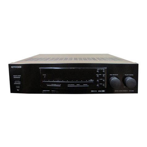
Kenwood KRF-V7771D User manual

Kenwood

Kenwood KRF-V7771D User manual

Kenwood 106VR User manual

Kenwood

Kenwood 106VR User manual

Kenwood 107VR User manual

Kenwood

Kenwood 107VR User manual

Kenwood KRF-V7050D User manual

Kenwood

Kenwood KRF-V7050D User manual

Kenwood KRF-X9090D User manual

Kenwood

Kenwood KRF-X9090D User manual

Kenwood KRF-V8010D User manual

Kenwood

Kenwood KRF-V8010D User manual

Kenwood R-V251 User manual

Kenwood

Kenwood R-V251 User manual

Kenwood 1080VR User manual

Kenwood

Kenwood 1080VR User manual

Kenwood KR-710 User manual

Kenwood

Kenwood KR-710 User manual

Popular Stereo Receiver manuals by other brands

Aiwa XR-H33MD Simplified service manual

Aiwa

Aiwa XR-H33MD Simplified service manual

Sony XAV-AX3250 operating instructions

Sony

Sony XAV-AX3250 operating instructions

Pioneer VSX-D514 operating instructions

Pioneer

Pioneer VSX-D514 operating instructions

Pioneer VSX-D908S operating instructions

Pioneer

Pioneer VSX-D908S operating instructions

Pioneer DMH-A241 BT quick start guide

Pioneer

Pioneer DMH-A241 BT quick start guide

Aiwa CX-ZL800 Service manual

Aiwa

Aiwa CX-ZL800 Service manual

Denon DRA-700AEDAB Service manual

Denon

Denon DRA-700AEDAB Service manual

Denon AVR-786 Service manual

Denon

Denon AVR-786 Service manual

Onkyo TX-NR901 Specification sheet

Onkyo

Onkyo TX-NR901 Specification sheet

Harman Kardon AVR 1600 Service manual

Harman Kardon

Harman Kardon AVR 1600 Service manual

Sony STR-DE997 - Fm Stereo/fm-am Receiver operating instructions

Sony

Sony STR-DE997 - Fm Stereo/fm-am Receiver operating instructions

Marantz NR1509 quick start guide

Marantz

Marantz NR1509 quick start guide

Anthem MRC 40 Series Installation and Usage Guide

Anthem

Anthem MRC 40 Series Installation and Usage Guide

Denon AVR-3806S operating instructions

Denon

Denon AVR-3806S operating instructions

Pioneer A9 SX-A9MK2-K operating instructions

Pioneer

Pioneer A9 SX-A9MK2-K operating instructions

Denon AVR-X4200W Service manual

Denon

Denon AVR-X4200W Service manual

Pioneer AVH-3400NEX Operation manual

Pioneer

Pioneer AVH-3400NEX Operation manual

Rotel RSX-1056 owner's manual

Rotel

Rotel RSX-1056 owner's manual

manuals.online logo
manuals.online logoBrands
  • About & Mission
  • Contact us
  • Privacy Policy
  • Terms and Conditions

Copyright 2025 Manuals.Online. All Rights Reserved.