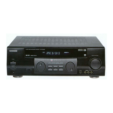
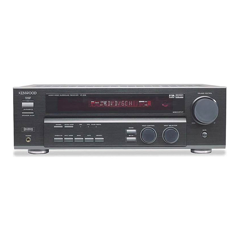
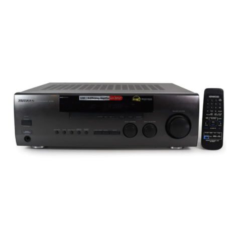
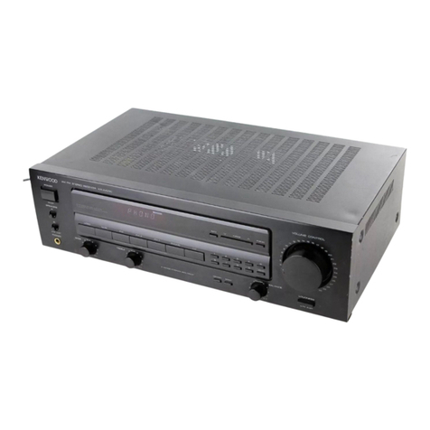
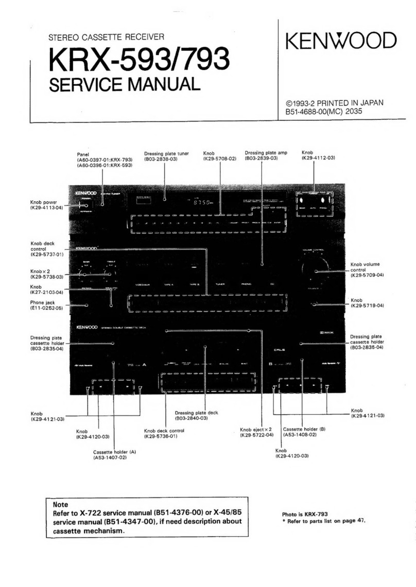
Kenwood KR-V9030 User manual

AUDIO/VIDEO
STEREO
RECEIVER
KR-V9030
INSTRUCTION
MANUAL
KENWOOD
CORPORATION
B60-0312-00(K,
P,
Y,
M)G@ADCSD
ET]
92/12
1110987654321
SI12110987654
GOO/ANAD

Introduction
(EE
aa
0
a
Your
choice
of
this
product
indicates
that
you
are
a
devotee
For
the
U.S.A.
to
excellence
in
sound
reproduction.
:
We
appreciate
your
patronage
and
take
pride
in
the
long
tradi-
Note
to
CATV
system
installer:
This
reminder
is
provided
to
call
the
CATV
system
in-
tion
of
quality
components
that
our
company
represents.
;
:
,
So
that
you
can
get
the
most
out
of
your
unit,
we
suggest
that
staller’s
attention
to
Article
820-40
of
the
NEC
that
pro-
vides
guidelines
for
proper
grounding
and,
in
particular,
you
take
the
time
to
read
through
this
manual
before
you
hook
>
¢
up
and
operate
your
system.
This
will
acquaint
you
with
oper-
specifies
that
the
cable
ground
shall
be
connected
to
the
grounding
system
of
the
building,
as
close
to
the
point
ating
features
and
system-connection
considerations
so
that
your
listening
pleasure
will
be
enhanced
right
from
the
start.
of
cable
entry
as
practical.
You
will
notice
that
in
all
aspects
of
planning,
engineering,
styling,
operating
convenience
and
adaptability
we
have
sought
to
anticipate
your
needs
and
desires.
Accessories
Keep
this
manual
handy
for
future
reference.
FM
indoor
antenna............
1
AM
loop
antenna..............
1
For
your
records
Record
the
serial
number,
found
on
the
back
of
the
unit,
in
the
spaces
designated
on
the
warranty
card,
and
in
the
space
provided
below.
Refer
to
the
model
and
serial
numbers
whenever
you
call
upon
your
dealer
for
information
or
service
on
this
product.
Model
___
ss
—~CSC«S@rrial
Number
:
75
Q/300
2
Loop
antenna
holder..........
1
antenna
adaptor
...............
]
Unpacking
Unpack
the
unit
carefully
and
make
sure
that
all
accessories
are
put
aside
so
they
will
not
be
lost.
Examine
the
unit
for
any
possibility
of
shipping
damage.
If
your
unit
is
damaged
or
fails
to
operate,
notify
your
dealer
immedi-
ately.
If
your
unit
was
shipped
to
you
directly,
notify
the
ship-
Bettas
BRAIGTASCOAUI
uci
acswes
1
ping
company
without
delay.
Only
the
consignee
(the
person
(RO3"
or
“AAA")
-cccccee.
4
or
company
receiving
the
unit)
can
file
a
claim
against
the
car-
rier
for
shipping
damage.
We
recommend
that
you
retain
the
original
carton
and
pack-
ing
materials
for
use
should
you
transport
or
ship
the
unit
in
the
future.
(Except
for
some
areas)
For
the
U.S.A.
FCC
WARNING
This
equipment
may
generate
or
use
radio
frequency
energy.
Changes
or
modifications
to
this
equipment
may
cause
harmful
interference
unless
the
modifications
are
expressly
approved
in
the
instruction
manual.
The
user
could
lose
the
authority
to
operate
this
equipment
if
an
unauthorized
change
or
modification
is
made.
Co
ntents
Caution:
Read
the
pages
marked
A
carefully
to
ensure
safe
operation.
IMHO
DUCTION:
bafeccsn
A
ues
eed
fan
adage
teense
cea
ae
vebeae
bettie
eas
2
Listening
to
a
broadcast
........0.0..c
cece
ee
ces
eeee
eee
sneeenenees
18
ABefore
applying
POWEF
.............cccceccseeeec
eee
ceeeeeeeeeeeeeeaneees
3
PRESCNGG
ocecc
Aur
ancs
cetecstoet
cnateade
ott
htat
Gtdudkonns
suhsw
eda
ges
eae
23
A
Safety
precautions..........000ccccceeceeeeseeeceeececceeceecceeeeecceeees
3
OO
PRoO-LoGic/
DO
3
STEREO
Mode..................20e
ee
25
AIMPORTANT
SAFEGUARDS
sats
OG
DSP
Presence
SYSTSMCONNECTONS
vos
conde
wrediesiennads
cewaserngncedeeeasacerented
6
Operation
of
video
components
................ceceeeceeee
eee
eeeeetes
31
FM
DE-EMPHASIS/CHANNEL
SPACE
switch
...............00066
9
Remote
control
operation...............
cece
cece
cnee
eee
ee
eee
ee
teens
32
Connection
of
video
components
IM
CASE:
OF
GITFCUNTY:.cccicccascies
ee
taesec
cates
ve
cote
casey
eenbes
...
88
Controls
and
indicators
A
SPOGCHICATIONS
vcs:
.ve.
seh
ban
ad
oles
Soa
Puke
eaten
ade
39
BASIC
sO
POratiONic
cece
ieccuc
ct
ceed
ceccnee
cue
baedennet
acute
tee
pola
yeeeeese
pan
2
KR-V9030
(En)

ACaution:
Read
this
page
carefully
to
ensure
safe
operation.
Before
applying
power
For
the
U.S.A.
and
Canada
Important!
Units
shipped
to
the
U.S.A.
and
Canada
are
designed
for
opera-
tion
on
120
volts
AC
only.
CAUTION:
To
PREVENT
ELECTRIC
SHOCK
DO
NOT
USE
THE
AC
PLUG
WITH
AN
EXTENSION
CORD,
RECEPTACLE
OR
OTHER
OUTLET
UNLESS
THE
BLADES
CAN
BE
FULLY
IN-
SERTED
TO
PREVENT
BLADE
EXPOSURE.
For
the
United
Kingdom
For
Australia
and
Europe
Important!
Units
shipped
to
Australia
are
designed
for
operation
on
240
V
AC
only.
:
Units
shipped
to
Europe
are
designed
for
operation
on
230
V
AC
only.
For
other
countries
Important!
Units
shipped
to
the
U.K.
are
designed
for
operation
on
240
volts
AC
only.
The
mains
plug
must
be
removed
from
the
wail
socket
prior
to
any
internal
examination.
The
wires
in
this
mains
lead
are
coloured
in
accordance
with
the
following
code:
BUG:
wassoteencacdsendtiy
stores
encete
Neutral
BrOWN
8
Sus
cucsesse
geadnweseeven
dees
pentose
Live
The
wires
in
this
mains
lead
must
be
connected
to
the
termi-
nals
in
the
plug
as
follows:
Wire
colour
Plug
terminal
marking
Blue:
eterna
age dai
tases
N
or
Black
BrOWNi
se
setzciecanicieersa
nents
aid
L
or
Red
(>
Brown
to
Live
Blue
to
Neutral
*
)
Plug
Notes:
1.
lf
a
13-amp
plug
is
used,
this
must
be
fitted
with
a
5-amp
fuse.
2.
If
a
3-pin
plug
with
earthing
contact
is
used,
no
wire
must
be
connected
to
the
E
terminal.
important!
Units
shipped
to
countries
other
than
the
above
countries
are
equipped
with
an
AC
voltage
selector
switch
on
the
rear
panel.
Refer
to
the
following
paragraph
for
the
proper
setting
of
this
switch.
AC
voltage
selection
This
unit
operates
on
110-120
or
220-240
volts
AC.
The
AC
voltage
selector
switch
Type
A
or
Type
B
on
the
rear
panel
is
set
to
the
voltage
that
prevails
in
the
area
to
which
the
unit
is
shipped.
Before
connecting
the
power
cord
to
your
AC
out-
let,
make
sure
that
the
setting
position
of
this
switch
matches
your
tine
voltage.
If
not,
it
must
be
set
to
your
voltage
in
ac-
cordance
with
the
following
direction.
Note:
Our
warranty
does
not
cover
damage
caused
by
excessive
line
voltage
due
to
improper
setting
of
the
AC
voltage
selector
switch.
AC
voltage
selector
switch
Type
A
areas
HRT
III
ACIS
acz20v~
Ac240v~
Type
B
=
mill
AC110V-
<»
AC220V-
120V
~
240V
~
Move
switch
lever
to
match
your
line
voltage
with
a
small
screwdriver
or
other
pointed
tool.
Safety
precautions
WARNING:
TO
PREVENT
FIRE
OR
ELECTRIC
SHOCK,-DO
NOT
EXPOSE
THIS
APPLIANCE
TO
RAIN
OR
MOISTURE.
CAUTION
RISK
OF
CLEC
THIC
SHOLK
DO
NOT
OPTS
CAUTION:
TO
REDUCE
THE
RISK
OF
ELECTRIC
SHOCK,
DO
NOT
REMOVE
COVER
(OR
BACK).
NO
USER-SERVICEABLE
PARTS
INSIDE,
REFER
SER-
VICING
TO
QUALIFIED
SERVICE
PERSONNEL.
THE
LIGHTNING
FLASH
WITH
ARROWHEAD
SYMBOL,
WITHIN
AN
EQUILATERAL
TRIANGLE,
IS
INTENDED
TO
ALERT
THE
USER
TO
THE
PRESENCE
OF
UNINSULATED
‘DANGEROUS
VOL-
TAGE’
WITHIN
THE
PRODUCT'S
ENCLOSURE
THAT
MAY
BE
OF
SUFFICIENT
MAGNITUDE
TO
CONSTITUTE
A
RISK
OF
ELECTRIC
SHOCK
TO
PERSONS.
THE
EXCLAMATION
POINT
WITHIN
AN
EQUILATERAL
TRIANGLE
IS
INTENDED
TO
ALERT
THE
USER
TO
THE
PRESENCE
OF
IMPORTANT
OPERATING
AND
MAINTENANCE
(SERVICING)
IN-
STRUCTIONS
IN
THE
LITERATURE
ACCOMPANYING
THE
APPLIANCE.
KR-V9030
(En)

IMPORTANT
SAFEGUARDS
A
Caution
:
Read
this
page
carefully
to
ensure
safe
operation.
Please
read
all
of
the
safety
and
operating
instructions
before
operating
this
unit.
For
best
results,
follow
all
warnings
placed
on
the
unit
and
adhere
to
the
operat-
ing
and
use
instructions.
These
safety
and
operating
in-
structions
should
be
retained
for
future
reference.
1.
Power
sources
—
The
unit
should
be
connected
to
a
power
supply
only
of
the
type
described
in
the
operating
instructions
or
as
marked
on
the
appliance.
2.
Power-cord
protection
—
Power-supply
cords
should
be
routed
so
that
they
are
not
likely
to
be
walked
on
or
pinched
by
items
placed
upon
or
against
them,
pay
particular
attention
to
cords
at
plugs,
convenience
receptacles,
and
the
point
where
they
exit
from
the
unit.
Never
pull
or
stretch
the
cord.
3.Grounding
or
polarization
—
The
precautions
should
be
taken
so
that
the
grounding
or
polariza-
tion
means
of
this
unit
is
not
defeated.
4.
Ventilation
—
The
unit
should
be
situated
so
that
its
location
or
position
does
not
interfere
with
its
proper
ventilation.
To
maintain
good
ventilation,
do
not
put
records
or
a
table-cloth
on
the
unit.
Place
the
unit
at
least
10
cm
away
from
the
walls.
Do
not
use
the
unit
on
a
bed,
sofa,
rug
or
similar
surface
that
may
block
the
ventilation
openings.
5.
Water
and
moisture
—
The
unit
should
not
be
used
near
water
—
for
example,
near
a
bathtub,
washbowIl,
kitchen
sink,
laundry
tub,
in
a
wet
base-
ment,
or
near
a
swimming
pool,
etc.
6.
Temperature
—
The
unit
may
not
function
pro-
perly
if
used
at
extremely
low,
or
freezing
tempera-
tures.
The
ideal
ambient
temperature
is
above
+
5°C
(41°F),
4
«r-v9030
(En)
7.Heat
—
The
unit
should
be
situated
away
from
heat
sources
such
as
radiators,
heat
registers,
stoves,
or
other
units
(including
amplifiers)
that
produce
heat.
.
Electric
shock
—
Care
should
be
taken
so
that
ob-
jects
do
not
fall
and
liquid
is
not
spilled
into
the
en-
closure
through
openings.
If
a
metal!
object,
such
as
a
hair
pin
or
a
needle,
comes
into
contact
with
the
inside
of
this
unit,
a
dangerous
electric
shock
may
result.
For
families
with
children,
never
permit
chil-
dren
to
put
anything,
especially
metal,
inside
this
unit.
9.Enclosure
removal
—
Never
remove
the
en-
closure.
If
the
internal
parts
are
touched
accidentally,
a
serious
electric
shock
might
occur.
10.
Magnetic
fields
—
Keep
the
unit
away
from
sources
of
magnetic
fields
such
as
TV
sets,
speaker
systems,
radios,
motorized
toys
or
magnetized
objects.
11.
Cleaning
—
Do
not
use
volatile
solvents
such
as
alcohol,
paint
thinner,
gasoline,
or
benzine,
etc.
to
clean
the
cabinet.
Use
a
clean
dry
cloth.

ACaution
:
Read
this
page
carefully
to
ensure
safe
operation.
12.
13.
14.
15.
16.
17.
Notes:
Carts
and
stands
—
An
appliance
and
cart
com-
bination
should
be
moved
with
care.
Quick
stops,
excessive
force,
and
uneven
surfaces
may
cause
the
appliance
and
cart
combination
to
overturn.
ve
==
Nonuse
periods
—
The
power
cord
of
the
unit
should
be
unplugged
from
the
outlet
when
left
un-
used
for
a
long
period
of
time.
Abnormal
smell
—
|f
an
abnormal
smell
or
smoke
is
detected,
immediately
turn
the
power
OFF
and
pull
out
the
power
cord.
Contact
your
dealer
or
nearest
service
center.
POWER
OFF!
Damage
requiring
service
—
The
unit
should
be
serviced
by
qualified
service
personnel
when:
A.
The
power-supply
cord
or
the
plug
has
been
damaged;
or
B.
Objects
have
fallen,
or
liquid
has
been
spilled
into
the
unit;
or
C.
The
unit
has
been
exposed
to
rain;
or
D.
The
unit
does
not
appear
to
operate
normally
or
exhibits
a
marked
change
in
performance;
or
E.
The
unit
has
been
dropped,
or
the
enclosure
damaged.
Servicing
—
The
user
should
not
attempt
to
ser-
vice
the
unit
beyond
that
described
in
the
operating
instructions.
All
other
servicing
should
be
referred
to
qualified
service
personnel.
Outdoor
antenna
grounding
—
If
an
outside
an-
tenna
is
connected
to
the
receiver,
be
sure
the
an-
tenna
system
is
grounded
so as
to
provide
some
protection
against
voltage
surges
and
built
up
static
charges.
Section
810
of
the
National
Electrical
Code,
ANSI/
NFPA
No.
70—1984,
provides
information
with
respect
to
proper
grounding
of
the
mast
and
supporting
structure,
grounding
of
the
lead-in
wire
to
an
antenna
discharge
unit,
size
of
grounding
con-
18.
19.
ductors,
location
of
antenna-discharge
unit,
connec-
tion
to
grounding
electrodes,
and
requirements
for
the
grounding
electrode.
See
Figure.
EXAMPLE
OF
ANTENNA
GROUNDING
AS
PER
NATIONAL
ELECTRICAL
CODE
ANTENNA
LEAD
IN
WIRE
ANTENNA
DISCHARGE
UNIT
(NEC
SECTION
810-20)
ELECTRIC
SERVICE
EQUIPMENT
{NEC
SECTION
810-21)
GROUND
CLAMPS
-a———~
POWER
SERVICE
GROUNDING
ELECTRODE
SYSTEM
(NEC
ART
250,
PART
H)
NEC
—
NATIONAL
ELECTRICAL
CODE
Power
lines
—
An
outdoor
antenna
should
be
lo-
cated
away
from
power
lines.
AC
outlets
—
Do
not
connect
other
audio
equip-
ment
with
a
power
consumption
larger
than
that
specified
to
the
AC
outlet
on
the
rear
panel.
Never
connect
other
electrical
units,
such
as
an
iron
or
toaster,
to
it
to
prevent
fire
or
electric
shock.
1.
Item
3
is
not
required
except
for
grounded
or
polarized
equipment.
2.
Item
17
and
18
are
not
required
except
for
units
provided
with
antenna
terminals.
3.
Item
17
complies
with
UL
in
the
U.S.A.
KR-V9030
(Eni
5

System
connections
Make
connections
as
shown
in
the
diagram
below.
When
connecting
the
related
system
components,
refer
also
to
the
in-
struction
manuals
of
the
related
components.
Do
not
plug
in
the
power
lead
until
all
connections
are
completed.
@
Connection
of
audio
components
Tape
deck
1
Tape
deck
2
LINE
IN=“LINE
QUT
PU
Y
FM
DE-EMPHASIS/
CHANNEL
SPACE
switch
(Except
for
some
areas.)
AC
outlet
(For
other
than
U.S.A.
and
Canada)
Refer
to
‘’Antenna
connection’
on
page
8.
SWITCHED
TOTAL
200W,
1.64
MAX,
=m
-
ACIZ0V
GOH
eee
ze,
=
|
FSS
To
oe
2
wall
ie)
|
irs)
=,
iS}
AC
L-
x
Actronzoy=
aca202¢0v-
outlet
Cc
™
IMPEDANCE
SELECTOR
ord
‘oro
LESS
THAN
ao
@N.OR
MORE
Aang
B0"OR
MORE
ay
we
=
©
®W
¢&
center
Lenzanad
PRE
OUT
PRE
OUT
jacks
Refer
to
page
7.
SOG
SRF
KKK)
Matas
5
eX
0,050;
~
+,
O00;
ese
SSC
?,
Turntable
Speaker
system
B
enter
speaker
SPEAKER
IMPEDANCE
SELECTOR
Refer
to
page
7.
AC
voltage
selector
Notes:
(Except
for
some
areas.)
1.
Connect
all
cords
firmly.
If
connections
are
loose,
there
could
be
loss
of
sound
or
noise
produced.
2.
Do
not
connect
up
a
power
source
which
is
larger
than
that
indicated
on
the
socket
at
the
rear
of
the
unit.
3.
When
plugging
and
unplugging
connection
cords,
be
sure
to
first
remove
the
power
cord
from
the
AC
outlet.
Plugging/unplugging
connection
cords
without
removal
of
the
power
cord
can
cause
malfunctions
or
damage
to
the
unit.
.
Never
short-circuit
the
+
and
—
speaker
cords.
5.
If
the
left
and
right
speakers
are
connected
inversely
or
if
the
speaker
cords
are
connected
with
reversed
polarity,
the
sound
becomes
unnatural
with
ambiguous
acoustic
image
positioning.
Be
sure
to
connect
the
speakers
and
speaker
cords
correctly.
&
6
KR-V9030
(En)

Connection
of
speaker
terminals
@
Push
lever.
@
Insert
cord.
J
@)
Lock
lever.
v
(ai
(fi
>
y
y
™@
Connection
of
PRE
OUT
jacks
Sound
will
not
be
output
from
the
speakers
if
they
are
connected
directly
to
the
PRE
OUT
jacks.
The
output
from
these
jacks
should
be
connected
to
speakers
with
built-in
amplifier.
or
to
exclusive
amplifiers
to
which
the
speakers
are
connected.
Center
speaker
Amplifier
R&R
8)
Amplifier
center
Lrecart
PRE
OUT
@
Use
these
jacks
if
you
want
to
listen
to
the
speakers
with
larger
volumes
or
with
different
tones.
lM
Setting
the
SPEAKER
IMPEDANCE
SELECTOR
According
to
the
impedance
of
the
speakers
used,
setthe
SPEAKER
IMPEDANCE
SELECTOR
on
the
rear
panel
as
IMPEDANCE
SELECTOR
shown
in
the
table.
AorB: AorB:
LESS
THAN
82 89
OR
MORE
@
During
speaker
system
connection
and
operation
of
the
Z
SPEAKER
IMPEDANCE
SELECTOR,
set
the
POWER
switch
Z
to
OFF.
SURROUND
ae
When
the
selector
is
at
the
position,
sound
will
AorB:
80
OR
MORE
not
be
heard
from
the
center
or
rear
speakers.
If
speakers
(with
amplifiers)
are
connected
to
the
PRE
OUT
jacks,
sound
will
be
heard
from
those
speakers.
AandB:
82
OR
MORE
.
»
@
When
Surround
speakers
are
connected
Surround
speakers
are
not
connected
Usable
speaker
impedance
Selector
position
Usable
speaker
impedance
Selector
position
A
or
B
speakers
42~60
A
or
B
speakers
8Q~162
:
<
A
and
B
speakers
Y
82~162
Center
speaker
89~160
A
or
B
speakers
82~162
Rear
speakers
82~160
KR-V9030
th)
7

System
connections
@
Push
lever.
@®
Insert
cord.
@®
Lock
lever.
a
ech
a.
@
AM
loop
antenna
connection
The
supplied
antenna
is
for
indoor
use.
Place
it
as
far
as
possible
from
the
main
system,
TV
set,
speaker
cords
and
power
cord,
and
set
it
to
a
direction
which
provides
the
best
reception.
@
Push
lever.
=),
@
Insert
conductor.
m=
@
Return
lever.
M@
FM
indoor
antenna
connection
@
Connect
to
the
screw
terminals.
@
Find
the
position
that
provides
best
reception.
@
Fix
two
ends.
B
KR-vg030
(En)
75us
A1O0KHz
=
100kHz
50us
¥
9kHz
50kHz
4
oe-
AM
FM
AM]
EMPHASIS
CHANNEL
SPACE
©}©
©|}©
©|O©
©
©O}O
OOO
@
AM
outdoor
antenna
connection
ie
"©©
if
the
reception
is
poor
when
the
AM
loop
antenna
is
used,
distribute
a
vinyl-coated
wire
of
more
than
6
meters
outdoors,
without
discon-
necting
the
loop
antenna.
HM
FM
outdoor
antenna
connection

@
75
©
coaxial
cable
connection
@
Arrange
the
coaxial
cable
as
illustrated.
@
Open
the
antenna
adaptor.
@®
Cut
off
the
red
wire
and
remove
it
from
the
clip.
Press
the
claws
in
the
direction
of
the
arrows
with
Lf
/
Remove
the
the
fingers
to
release
the
lock
and
pul!
out
the
red
wire
Outer
shield
(Braid)
Inner
:
conductor
—
RG-6
(5C-2V)
or
RG-59
(3C-2V)
@
Insert
into
the
slit
on
the
clip.
Fasten
the
bands
A
and
B,
using
a
pair
of
pliers.
we
FM
DE-EMPHASIS/CHANNEL
SPACE
switch
(Except
for
some
areas)
The
FM
DE-EMPHASIS/CHANNEL
SPACE
switch
on
the
rear
panel
is
set
to
the
correct
setting
that
prevails
in
the
area
to
which
the
unit
is
shipped.
However,
if
the
FM
DE-EMPHASIS/CHANNEL
SPACE
set-
|
CHANNEL
FM
DE-
ting
is
not
matched
to
the
area
where
the
unit
is
to
be
used;
for
in-
mies
SPACE
freq.
EMPHASIS
stance,
when
you
move
from
area
1
to
area
2
or
vice
versa,
desired
reception
of
AM/FM
broadcasts
is
not
expected.
In
this
case,
change
1.|
U.S.A.,
Canada
|
the
FM
DE-EMPHASIS/CHANNEL
SPACE
setting
in
accordance
with
snd
South
PMs:
OO
eie
75
ps
the
area
corresponding
to
the
table.
The
FM
DE-EMPHASIS
is
switched
American
countries
AM:
10kHz
over
at
the
same
time.
7
‘
FM:
5OkHz
2.|
Other
countries
AM:
9kHz
50
ps
ree
|
75us
A
10kHz
100kHz
®
When
changing
the
setting
of
the
FM
DE-EMPHASIS/CHANNEL
5Ous
Vo
9kHz
50kHz
SPACE
switch,
first
disconnect
the
power
cord,
then
reset
the
chan-
. :
AM
FM
nel
space
switch,
connect
the
power
cord
again,
and
turn
the
pow-
DE-
er
on.
EMPHASIS
CHANNEL
SPACE
KR-V9030
(fy
9

System
connections
Connection
for
system
control
operation
Using
the
system
control
cords
provided
with
KENWOOD
system
component
models,
make
connections
as
shown
below.
*
For
a
cassette
deck
to
be
subject
to
system
control
operation,
it
must
be
connected
to
the
TAPE
1
jacks.
3
"
H
CD
player
)
System
control
cord
System
control
connection
©
Be
sure
to
insert
the
system
control
cord
plugs
fully
into
the
SYSTEM
CONTROL
terminals.
®
!f
the
system
control
cord
and
audio cords
are
not
connected
Properly,
the
automatic
system
governing
remote
control
and
sys-
tem
functions
will
not
operate.
Turntable
Operation
By
connecting
this
unit
to
KENWOOD
cassette
deck,
CD
player
and
turntable
models
equipped
with
system
control
jacks,
the
following
integrated
operation
features
become
available.
1.
Automatic
play
operation
When
starting
play
with
the
turntable,
cassette
deck,
or
CD
play-
er
connected
to
the
receiver,
press
the
desired
input
selector
keys
on
the
receiver.
The
turntable,
cassette
deck,
or
CD
player
will
automatically
enter
play
mode.
In
the
same
way,
pressing
the
Play
key
of
the
turntable,
cassette
deck,
or
CD
player
will
automatically
switch
the
input
selector
on
the
receiver
to
the
component
on
which
the
Play
key
is
pressed.
2.
Synchro
recording
To
record
the
sound
from
the
CD
player
or
turntable
onto
a
tape
with
the
cassette
deck,
press
the
CD
or
PHONO
of
the
input
selector
keys
and
load
a
CD
or
record.
Set
the
cassette
deck
to
rec
pause
mode,
then
press
the
Play
(start)
key
of
the
CD
player
or
turnta-
ble.
The
cassette
deck
will
start
recording
automatially,
syn-
chronized
with
the
CD
player
or
turntable
starting
play.
3.
Remote
control
The
remote
contro!
unit
provided
with
this
unit,
to
which
a
KENWOOD
system
turntable,
cassette
deck,
or
CD
player
is
con-
nected,
is
equipped
with
related
control
keys.
The
related
com-
ponents
can
be
controlled
using
these
keys.
10°
KR-vgo30
(En)

Connection
of
video
components
For
the
connections
and
operations,
also
read
carefully
the
instruction
manuals
supplied
with
the
video
components
to
be
connected.
VIDEO
DECK
2
AUDIO
IN
AUDIO
OUT
VIDEO
OUT
VIDEO
iN
VIDEO
IN
VIDEO
OUT
AUDIO
IN
AUDIO
OUT
VIDEO
IN
Monitor
TV
F
‘
Somes,
SS,
ESO
mae
2
See
Sle]
See
===
aE
=
eeae
0Un
ass
OO]
S-VIDEO
jacks
In
the
S-Video
(Y/C
separated)
signal
transmission
system,
the
regu-
lar
video
signal
(composite
signal)
is
separated
into
a
signal
identify-
ing
the
brightness
(Y:
juminance)
and
a
signal
identifying
the
color
(C:
chroma)
to
be
transmitted.
Use
of
these
jacks
provides
improved
picture
quality.
When
the
S-VIDEO
jacks
are
to
be
used,
please
read
carefully
the
instruction
manuals
of
the
video
components.
@
Connection
of
monitor
TV
Connect
the
video
input
jack
of
the
monitor
TV
to
the
MONITOR
OUT
jack
on
the
rear
panel
using
a
video
con-
nection
cord.
If
the
monitor
TV
is
equipped
with
an
S-VIDEO
input
jack,
connect
it
to
the
S-VIDEO
jack
of
this
unit.
Notes:
.
1.
Whena
video
signal
is
input
to
this
unit
through
the
composite
Connection
of
VIDEO
3
(AUDIO
IN,
VIDEO
IN)
VIDEO
jack,
the
same
signal
is
not
output
from
the
S-VIDEO
jack
of
the
MONITOR
OUT
jacks.
2.
Whena
video
signal
is
input
to
this
unit
through
the
S-VIDEO
jack,
the
same
signal
is
not
output
from
the
MONITOR
OUT
video
jack.
a
VIDEO
3
VIDEO.
L
AUDIO
R
pi
@
Connection
of
VCRs
o
The
VIDEO
2
inputs/outputs
can
be
connected
through
the
S-VIDEO
jacks.
Therefore,
recording
a
video
source
of
the
component
connected
to
S-VIDEO
jacks
is
possible.
Note:
Dubbing
between
a
VCR
connected
to
a
composite
input/output
and
a
VCR
connected
to
an
S-VIDEO
input/output
is
not
possible.
@
Connection
of
other
video
components
The
S-VIDEO
input
jacks
are
also
provided
for
the
VIDEO
3
inputs.
Therefore,
recording
a
video
source
of
the
com-
ponent
connected
to
VIDEO
2
S-VIDEO
jacks
is
possible.
Note:
:
When
connect
to
the
KENWOOD
LD
player
having
Dubbing
between
a
video
component
connected
to
a
composite
system
control
terminal,
do
not
connect
anything
to
input/output
and
a
video
component
connected
to
an
S-VIDEO
the
system
control
terminal
of
the
LD
player.
input/output
is
not
possible.
x
KR-Vg030
(En
11

Controls
and
indicators
Remote
control
light
receptor
BYPASS
key
ipUT
LEVEL
keys
O00
PRO-LOGIC
key
LINE
STRAIGHT
key
TUNING
keys
POWER
key
003
STEREO
key
CD
DIRECT
key
+10
key
VOLUME
CONTROL
with
point
indicator
STAND
BY
indicator
soceted
Salil
ECEIVER
KR-VSO:
ae
BAND
key
KENWOOD
Fl
BYPASS
_UPROLOGIC
[3
STEREO
SP.
=
NeuT
ceven
LINE
STRAIGHT
_
cD
DIRECT
BAND
VOLUME
CONTROL
PHONES:
PHONES
jack
Input
select
keys
Numeric
keys
BALANCE
control
knob
LOUDNESS
control
knob
SPEAKERS
A
and
B
switches
A,
B
OFF
-—
This
position
silences
all
speakers
to
permit
private
use
of
headphones.
AON
—
Activates
speakers
connected
to
the
SPEAKERS
A
ter-
minals
on
the
rear
panel.
Before
operating
the
unit,
remove
packing
material
as
BO
a
i
N
Activates
the
speakers
connected
to
the
SPEAKERS
ahown
felow.
B
terminals
on
the
rear
panel.
A,
BON
—
Activates
the
speakers
connected
to
the
SPEAKERS
A
and
B
terminals
simultaneously.
SPEAKERS
A
STAND
BY
mode
of
POWER
switch
When
the
power
cord
of
this
system
is
plugged
into
an
AC
outlet,
the
STAND
BY
indicator
lights
up
regardless
of
the
ON/OFF
setting
©
©
If
you
press
the
[1]
PRO-LOGIC
key,
D0
3
STEREO
key
or
DSP
of
the
POWER
switch.
This
indicates
that
a
small
amount
of
current
key
when
both
the
A
and
B
SPEAKERS
switches
are
ON,
the
unit
is
being
supplied
to
the
unit
to
back
up
the
memory
contents.
This
will
automatically
switch
to
A
so
that
sound
is
heard
only
from
the
mode
is
referred
to
as
the
Stand
By
mode.
While
the
STAND
BY
indi-
A
speakers.
Pressing
the
B
key
at
this
time
will
switch
the
sound
cator
is
lit,
the
power
of
the
system
can
be
switched
ON/OFF
from
So
that
it
is
heard
from
the
B
speakers
only.
the
remote
control
unit.
12.
kR-vg030
(En)

(Ep
a
A
I
I
I
TS
TS
eS
DSP
indicators
SPEAKERS
A
and
B
indicators
(
GATHE
JAZZ CLUB
STADIUM
pecorseov
CATHEDRAL
MOVIE
CD
DIRECT
indicator
CHANNEL
MODE
MEMORY
adi
indicators
indicator
OVER
LEVEL
indicator
(3
CHANNEL
indi
4
CHANNEL
VISUAL
FIX
nace
MODE
indicators
indicator
CCIPRO-LOGIC
D.S.P.S.
003
STEREO
indicator
DSP
SPEAKERS
JAZZ
CLUB
STADIUM
DISCOTHEQUE
———
DOPRO.LOgIC
3
STEREO
osP
@
CHANNEL
4
CHANNEL:
I)
IOI
WAL
ILI
iid
ae
JAN
WANT
WANT
ANT
ANT
AST
WAST
HAT
AST
AST
ATT,
AUTO
indicator
VIDEO
MONITOR
1
2
Sindicators
|
LINE
STRAIGHT
indicator
STEREO
indicator
Information
display
Tuning
frequency
and
preset
number
TUNED
indicator
Broadcasting
name
Input
source
Center
and
rear
speaker's
level
Delay
time
Input
level
Presence
level
TAPE
2
indicator
Push
the
bottom
side
of
the
door
to
open.
a
es
ee
4
oa
=
*
[rll
=ll-]
SSSSS|
CENTER
LEVEL
|
VISUAL
FIX
key
Push
up
the
top
side
of
the
door
control
keys
to
close.
MEMORY
key
CENTER
MODE
key
DIRECT
key
AUTO
key
VIDED
2
MODE
VISUAL
FIX
MEMORY
DIRECT
AUTO
:
2
FLAT
2
;
:
2
FLAT
9
:
OObE
P.SCAN
DIGIT
CHARACTER
O:
©:
S-VIDEO
jack
control
keys
sald
eae
knobs
VIDEO
jack
|
CHANNEL
MODE
key
TREBLE
AUDIO
L
and
R
jacks
D.S.P.S.
key
CHARACTER
key
DIGIT
key
P.SCAN
key
KR-vg030
(Eni
13

Basic
operation
@
Basic
operation
1
Press
the
POWER
key
to
ON.
QN/STAND
BY
2
Select
an
input
source.
The
source
name
characters
appear
on the
display.
Pee
beac
Redcat
|
wore]
oar
|
rare2|
ares]
ninen
|
mono
|
co
|
@
When
the
cassette
deck,
CD
player
and
turntable
are
con-
nected
via
the
system
control
cord,
any
of
these
source
com-
ponents
starts
to
be
played
automatically
when
the
corresponding
input
select
key
is
pressed.
POWER
key
Display
VOLUME
CONTROL
Tone
controls
BASS,
TREBLE
LOUDNESS
control
BALANCE
control
PHONES
jack
Input
select
keys
4
Adjust
the
volume
VOLUME
CONTROL
Main
unit
Remote
control
unit
@
When
the
volume
is
adjusted
from
the
remote
control
unit,
the
VOLUME
CONTROL
knob
on
the
main
unit
rotates
while
the
point
indicator
is
blinking.
5
Adjust
the
left
and
right
volume
balance.
Penance
L
R
3
Play
the
source
component.
14
kR-vg030
(En)
6
Adjust
the
tone.
TREBLE
2
FLAT
2
Adjusts
the
Adjusts
the
low
frequencies.
S
high
frequencies.
8

M@
To
mute
the
sound
temporarily
Remote
control
unit
only
Press
the
MUTE
key
on
the
remote
control
unit.
@
The
indicator
on
the
VOLUME
CONTROL
knob
on
the
front
panel
blinks
@
Pressing
the
key
again
resumes
the
previous
volume.
PHONES
jack
VOLUME
CONTROL
Input
select
keys
LOUDNESS
control
M@
Listening
with
headphones
1
Set
the
unit
to
BYPASS.
BYPASS
BYPASS
Main
unit
(hy
Remote
control
unit
@
When
playing
in
any
of
presence
modes,
sound
from
the
center
and
rear
speakers
will
not
be
cut
off
unless
the
presence
mode
is
canceied
by
pressing
the
BYPASS
key.
if
you
want
to
listen
to
sound
played
back
in
presence
mode
using
headphones,
set
the
volume
to
minimum.
2
Plug
the
headphones
into
the
PHONES
jack.
PHONES
@
Set
the
A
and
B
SPEAKERS
switches
to
OFF.
LOUDNESS
control
Listening
athigh
volume
allows
to
enjoy
dynamic
sound,
but
human
ears
tend
to
feel
low
frequencies
insufficient
when
listening
at
low
volume.
When
the
VOLUME
CONTROL
is
set
to
a
low
position,
the
insufficiency
of
low
frequencies
felt
by
human
ears
can
be
compen-
sated
by
turning
the
LOUDNESS
control
clockwise.
LOUDNESS
‘
O
Enhances
low
frequencies.
ze)
10
@
The
effect
of
LOUDNESS
control
is
less
sensible
if
the
VOLUME
CONTROL
is
set
to
the
center
position
or
above.
3
Adjust
the
volume.
VOLUME
CONTROL
14,1510
45
®
Turn
the
volume
all
the
way
down
before
unplugging
the
headphones.
‘
Notes:
1.
When
TAPE
2
is
ON,
you
cannot
listen
to
the
source
selected
by
the
input
select
keys.
To
listen
to
the
selected
source,
set
TAPE
2
to
OFF.
.
2.
Even
if
the
power
cord
is
unplugged,
the
currently
selectedsource
is
stored
in
memory
for
several
days.
After
this
period
elapses,
however,
the
source
is
automatically
switched
to
TUNER.
“KR-V9030
(én)
15

Basic
Operation
@
Operation
of
CD
DIRECT
playback
The
digital
sound
of
Compact
Disc
features
an
ideal
reproduction
characteristics,
and
the
sound
quality
provided
by
CD
can
be
reproduced
with
least
degradation
by
means
of
the
CD
direct
playback
function.
|
Press
the
CD
DIRECT
key.
LINE
STRAIGHT
CD
DIRECT
co
omect,
®
CD
DIRECT
indicator
lights
up.
2
Play
the
CD
player.
PLAY/PAUSE
@
The
CD
DIRECT
selection
is
given
priority
to
any
other
source
being
selected
by
the
input
select
key.
To
cancel
the
CD
DIRECT
playback
function
Press
the
CD
DIRECT
key
again,
or
select
the
input
select
key.
LINE
STRAIGHT
CD
DIRECT
®
CD
DIRECT
indicator
goes
off.
Note:
LINE
STRAIGHT
key
CD
DIRECT
key
KENWOOD
—
avoto.vioro
aTeneo
nrcKiven
emvoese
input
slect
key
H
Operation
of
LINE
STRAIGHT
playback
This
CD,
with
least
degradation
of
sound
quality.
1
Select
an
input
source.
VES
[NIBEO.
2
|
wero]
var
[raves]
rarer]
ruven
[
evono
|
co
|
2
Press
the
LINE
STRAIGHT
key.
LINE
STRAIGHT
CD
DIRECT
@
LINE
STRAIGHT
indicator
lights
up.
3
Play
the
input
source.
To
cancel
the
LINE
STRAIGHT
playback
Press
the
LINE
STRAIGHT
key
again.
LINE
STRAIGHT
CD
DIRECT
@
LINE
STRAIGHT
indicator
goes
off.
During
CD
DIRECT
or
LINE
STRAIGHT
playback,
the
tone
controls
do
not
function.
1B
KR-v9030
(En)

@
Ordinary
tape
recording
Select
the
source
to
be
recorded.
Set
cassette
deck
1
or
2
in
the
record-pause.
So
O
moo)
59
Record-pause
mode
Play
the
source
component
to
be
recorded,
and
start
recording
it
on
the
cassette
deck.
Recording
starts.
@
Tape
dubbing
TAPE
1
—
TAPE
2
Play
the
cassette
deck
connected
to
TAPE
1
and
record
on
the
cas-
sette
deck
connected
to
TAPE
2.
TAPE
2
—
TAPE
1
1
Press
the
TAPE
2
key.
(MONITOR)
TAPE
2
TAPE
TAPE
2]
indicator
lights
up.
2
Select
a
source
other
than
TAPE.
ve
[MEO
2
|
vor
1]
oar
[rarez|
rare
|
ruven
|
puono
|
co
|
~
3
Play
cassette
deck
2
and
start
recording
on
cassette
deck
1.
@
Do
not
select
TAPE
1
while
dubbing.
Note:
For
the
tape-to-tape
dubbing
procedure
using
a
double-deck
type
cas-
sette
deck,
please
read
the
instruction
manual
provided
with
the
double-deck
type
cassette
deck.
@
Listening
to
CD
while
recording
another
source
1
Select
the
source
to
be
recorded.
coer
Neue
ota
Nsbacard
ie
[rarer]
ren
|
move
|
co
|
w
3
Start
recording
on
the
cassette
deck
connected
to
the
TAPE
1
jacks.
O
Recording
starts.
2
Play
the
source
to
be
recorded.
4
Press
the
CD
DIRECT
key.
LINE
STRAIGHT
CD
DIRECT
CD
DIRECT
indicator
lights
up.
5
Play
the
CD
player.
@
No
other
source
can
be
selected
until
the
cassette
deck
record-
ing
is
stopped.
@
The
source
name
on
the
display
remains
the
same,
i.e.
the
name
of
the
recorded
source.
KR-V9030
(En)
17

Listening
to
a
broadcast
M@
Receiving
broadcast
stations
and
storing
them
in
memory
(preset
operation)
TUNER
@
Previous
reception
mode
is
resumed.
@
Pressing
the
BAND
key
also
set
the
unit
to
tuner
mode.
Main
unit
(hy
Remote
control
unit
1
Select
the
TUNER
input
with
the
input
selector.
Select
the
broadcast
band
(FM,
AM).
TUNER
Remote
control
unit
Each
time
the
BAND
key
is
pressed,
the
reception
:
;
band
changes
between
FM
and
AM.
Main
unit
Enter
the
AUTO
tuning
mode.
AUTO
|
indicator
lights
up.
=
WaT
a
@
The
indicator
goes
on
(auto)
and
off
(manual)
alternately
every
time
the
key
is
pressed.
Normally,
select
the
auto
tuning
mode.
Tune
a
desired
station.
To
decrease
To
increase
Auto
tuning
mode
Manual
tuning
mode
frequen
fr
quency
~~
otunne
=A
Oequency
_—__
=
fc
aon
Press
once.
(Tuning
Press
repeatedly,
or
thy
ty
The
TUNED
indi
me
stops
automatically
when
|
press
and
hold,
until
the
e
indicator
lights
up
: :
:
‘
‘
;
when
a
station
is
received.
a
station
is
received.)
station
is
received.
TUNING
keys
on
the
main
unit
@
When
the
TUNING
UP
key
is
pressed,
the
frequency
increases.
When
the
TUNING
DOWN
key
is
pressed,
the
frequency
decreases.
@
Use
manual
tuning
mode
in
case
the
radio
wave
is
weak
and
noisy.
At
this
time,
the
stereo
FM
broadcast
is
received
in
monaura!
mode.
Store
the
stations
in
preset
memory.
@
Press
the
MEMORY
key.
—
(for
about
5
seconds).
MEMORY
indicator
lights
up
_
DAT
Me
PEhgreie
=
cc
ad
=
es
tt
c
E
®@
Proceed
the
step
@
while
the
MEMORY
indicator
is
lighted.
@)
Press
the
numeric
keys
to
preset
the
station.
Examples
To
select
preset
No.
To
select
preset
No.
To
select
preset
No.
To
select
preset
No.
MEMORY
indicator
goes
off.
®@
A
total
of
30
stations
can
be
preset
in
memory
regardless
of
their
broadcast
bands.
®@
if
a
station
has
been
preset
under
the
numeric
key
pressed,
the
previous
preset
content
is
replaced
by
the
new
station.
@
Repeat
step
2
to
5
above
for
each
of
other
stations
to
be
preset.
18
kR-vg030
(En)

lM
Receiving
a
preset
station
Select
the
TUNER
input
with
the
input
selector.
2
Select
the
desired
station.
Press
the
numeric
key
under
which
the
station
is
preset.
tn
ee
ee
poh
eae
SS
5
—i—i—i
—
i
—
Example
To
select
preset
No.
15,
press
the
key
once,
then
the
[5]
key
once.
®@
The
frequency
of
the
station
received
will
be
displayed.
i
Listening
to
all
preset
stations
in
sequence:
PRESET
SCAN
Press
the
P.SCAN
key.
|
Main
unit
(hy
S&S
Remote
control
unit
@
Preset
stations
are
received
in
order
of
1>2->3...10...20
...30
1
every
time
the
key
on
the
main
unit
is
pressed.
With
the
key
on
the
remote
control
unit,
preset
stations
are
received
in
order
of
1+2-+...10...
every
time
the
[A]
(UP)
key
is
pressed,
or
in
order
of
30>
29...20...
every
time
the
[V]
(DOWN)
key
is
pressed.
Holding
one
of
these
keys
pressed
recalls
the
preset
stations
in
sequence
at
0.5-second
intervals.
When
the
key
is
released,
the
current
preset
station
is
received.
ETH-0100R
BAND
key
Numeric
keys
D.S.P.S.
key
|
DIRECT
key
P.SCAN
key
@
Direct
tuning
of
radio
stations
If
you
know
the
frequency
of
the
desired
station,
it
can
be
received
directly
by
inputting
the
frequency
using
the
nu-
meric
keys.
Select
the
broadcast
band.
@
FM
or
AM.
Press
the
DIRECT
key.
DIRECT
Main
unit
thy
Remote
control
unit
D.S.P.S.
(Direct
Surround
Preset
Station)
function
\f
you
set
a
desired
surround
mode
when
presetting
a
broadcast
sta-
tion,
that
surround
mode
will
be
automatically
recalled
when
you
recall
the
preset
station.
Pressing
the
D.S.P.S.
key
turns
the
surround
recall
function
ON
and
OFF.
The
surround
setting
can
be
changed
if
desired.
See
page
22
for
details.
0.S.P.S.
Last
channel
memory
When
the
band
selector
is
switched
or
when
the
input
selector
is
switched
from
another
source
to
TUNER,
the
last
received
station
is
recalled
foreach
of
FM,
AM
when
the
power
is
switched
ON.
Input
the
frequency
of
the
desired
station
by
pressing
the
numeric
keys.
1
2
3
4
5
oo
ca
co
co
cS
6
Z
8
9
°
cS
cS
co co
Co
w
Example
of
input
Desired
station
Order
of
pressing
numeric
keys
FM
90
MHz
(100
kHz
space
)
0,
0,
(
50
kHz
space
}
102.5
MHz
(100
kHz
space
}
{
50
kHz
space}
810
kHz
(
9
kHz
space)
(
10
kHz
space
}
1260
kHz
6,
{(
9
kHz
space)
6
(
10
kHz
space)
If
you
commit
a
mistake
in
the
input
of
numeric
keys,
Fe-
start
the
input
from
the
beginning.
KR-V9030
(i
19

Listening
to
a
broadcast
BAND
key
_
MEMORY
key
TUNING
key
KENWOOD
suo.
vO8O
STEREO
RECEIVER
caBIG
=
pane
a
Sarma
|
pape
Oo]
OO
M@
Displaying
station
names
Station
names
composed
of
up
to
four
digits
of
characters
and/or
symbols
can
be
displayed
on
the
display.
Example:
To
receive
FM
98.80
MHz,
input
its
name
with
characters
“CBE’’,
and
preset
them
under
numeric
key
[3].
eCod
sil
soe
re
©:
*
6
DIGIT
key
CHARACTER
key
Numeric
keys
1
Receive
FM
98.80
MHz,
and
enter
the
character
input
mode.
CHARACTER
2
Select
the
characters
to
be
displayed
with
that
station.
@
Display
the
desired
character.
Types
of
characters
that
can
be
input
w
TUNING
“~~
After
having
pressed
the
CHARACTER
key,
press
the
TUNING
key
to
display
the
characters
available.
—_ABCD
«
L
Blank
position
3210/-+
@
Establish
the
selection.
Blinking
digit
changes
to
the
next
digit.
Ne
@
Repeat
steps
@
and
@
until
all
of
the
required
characters
have
been
input.
®
To
select
‘‘C’’,
press
the
UP
segment
three
times.
®
To
insert
a
space,
simply
press
the
DIGIT
key.
End
the
character
input.
CHARACTER
@
The
character
input
also
terminates
automatically
when
fourth
character
has
been
input.
@
Press
the
CHARACTER
key
to
terminate
character
input
with
three
characters
or
less.
Preset
them
under
key
[3]
.
@
Press
the
MEMORY
key.
®
Proceed
the
step
@
while
the
MEMORY
indicator
is
lighted.
MEMORY
indicator
lights
up
(for
about
5
seconds).
®
Press
the
numeric
key
[3]
.
ano
MEMORY
indicator
goes
off.
=
es
ran
3
4
5
=
Cre
coc
coc
6
7
9
is)
coco
os
fend
of
preset
20
KR-v9030
(En)
Table of contents
Other Kenwood Stereo Receiver manuals

Kenwood
Kenwood KR-V8040 User manual

Kenwood
Kenwood KRF-V5200D User manual

Kenwood
Kenwood KR-V8030 User manual

Kenwood
Kenwood KR-V5580 User manual

Kenwood
Kenwood VR-509 User manual

Kenwood
Kenwood VR-606 User manual

Kenwood
Kenwood KR-A5080 User manual

Kenwood
Kenwood KR-V6080 User manual

Kenwood
Kenwood KR-A4030 User manual

Kenwood
Kenwood 1090VR User manual

Kenwood
Kenwood KR-795 User manual

Kenwood
Kenwood VR-9050 User manual

Kenwood
Kenwood VRS-6200 User manual

Kenwood
Kenwood KR-710 User manual

Kenwood
Kenwood VR-510 User manual

Kenwood
Kenwood C-V351 User manual

Kenwood
Kenwood AR-304 User manual

Kenwood
Kenwood KR-A5050 User manual

Kenwood
Kenwood KRC-754 D User manual

Kenwood
Kenwood KRC-535 User manual