manuals.online logo
Brands
  1. Home
  2. •
  3. Brands
  4. •
  5. Kenwood
  6. •
  7. Stereo Receiver
  8. •
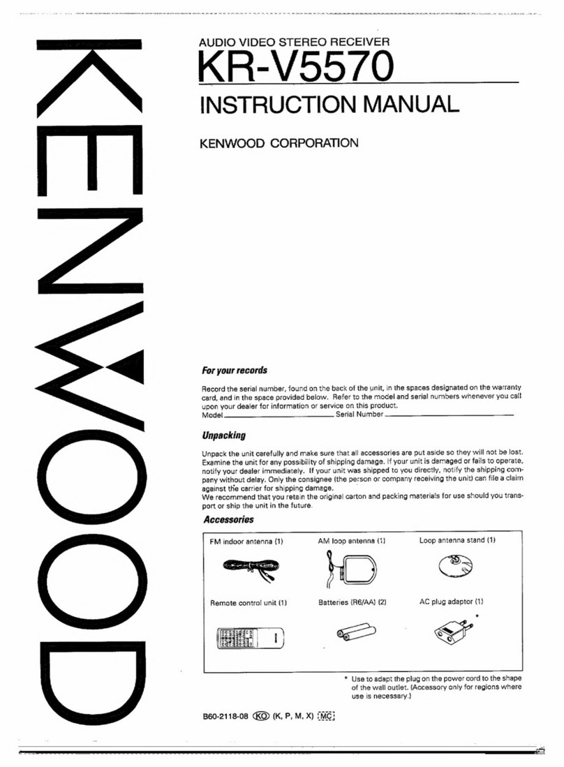
  9. Kenwood A-711 User manual

Kenwood A-711 User manual

Other manuals for A-711

1

This manual suits for next models

1

Other Kenwood Stereo Receiver manuals

Kenwood KR-V8030 User manual

Kenwood

Kenwood KR-V8030 User manual

Kenwood KRC-508S User manual

Kenwood

Kenwood KRC-508S User manual

Kenwood krf v5080d User manual

Kenwood

Kenwood krf v5080d User manual

Kenwood 1080VR User manual

Kenwood

Kenwood 1080VR User manual

Kenwood VR Series User manual

Kenwood

Kenwood VR Series User manual

Kenwood DVR-6200 User manual

Kenwood

Kenwood DVR-6200 User manual

Kenwood KR-V77R User manual

Kenwood

Kenwood KR-V77R User manual

Kenwood KRC-208S/218 User manual

Kenwood

Kenwood KRC-208S/218 User manual

Kenwood KRF-X9060D User manual

Kenwood

Kenwood KRF-X9060D User manual

Kenwood KR-A5080 User manual

Kenwood

Kenwood KR-A5080 User manual

Kenwood KR-V6040 User manual

Kenwood

Kenwood KR-V6040 User manual

Kenwood 1090VR User manual

Kenwood

Kenwood 1090VR User manual

Kenwood R-2000 User manual

Kenwood

Kenwood R-2000 User manual

Kenwood 103AR User manual

Kenwood

Kenwood 103AR User manual
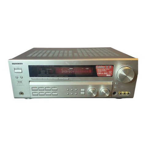
Kenwood KR-6170 User manual

Kenwood

Kenwood KR-6170 User manual

Kenwood KR-V86R User manual

Kenwood

Kenwood KR-V86R User manual

Kenwood KR-7400 User manual

Kenwood

Kenwood KR-7400 User manual

Kenwood KR-A5520 User manual

Kenwood

Kenwood KR-A5520 User manual

Kenwood VR-509 User manual

Kenwood

Kenwood VR-509 User manual

Kenwood KRC-21SA User manual

Kenwood

Kenwood KRC-21SA User manual

Kenwood VR-7070 User manual

Kenwood

Kenwood VR-7070 User manual

Kenwood KRF-V8010D User manual

Kenwood

Kenwood KRF-V8010D User manual

Kenwood KRF-V8080D User manual

Kenwood

Kenwood KRF-V8080D User manual

Kenwood DVR-6300 User manual

Kenwood

Kenwood DVR-6300 User manual

Popular Stereo Receiver manuals by other brands

Teac AG-680 Service manual

Teac

Teac AG-680 Service manual

Teac AGV1050 owner's manual

Teac

Teac AGV1050 owner's manual

Sony STR-435 operating instructions

Sony

Sony STR-435 operating instructions

Pioneer Elite SC-68 Service manual

Pioneer

Pioneer Elite SC-68 Service manual

Pioneer SX-1250 operating instructions

Pioneer

Pioneer SX-1250 operating instructions

Marantz CINEMA 70S owner's manual

Marantz

Marantz CINEMA 70S owner's manual

Yamaha RX-830 owner's manual

Yamaha

Yamaha RX-830 owner's manual

Pioneer AVH-Z7250BT owner's manual

Pioneer

Pioneer AVH-Z7250BT owner's manual

Denon AVR-1311 owner's manual

Denon

Denon AVR-1311 owner's manual

Denon AVR-S760H owner's manual

Denon

Denon AVR-S760H owner's manual

Denon AVR-X7200W Service manual

Denon

Denon AVR-X7200W Service manual

Sony XAV-1500 operating instructions

Sony

Sony XAV-1500 operating instructions

Radio Shack DX-399 owner's manual

Radio Shack

Radio Shack DX-399 owner's manual

Sony STR-DE535 - Fm Stereo/fm-am Receiver operating instructions

Sony

Sony STR-DE535 - Fm Stereo/fm-am Receiver operating instructions

Pioneer SX-1000TA operating instructions

Pioneer

Pioneer SX-1000TA operating instructions

Yamaha MusicCast TSR-5B3D owner's manual

Yamaha

Yamaha MusicCast TSR-5B3D owner's manual

Sony STR-DG500 - Multi Channel Av Receiver Service manual

Sony

Sony STR-DG500 - Multi Channel Av Receiver Service manual

Sherwood Newcastle RX-770 operating instructions

Sherwood

Sherwood Newcastle RX-770 operating instructions

manuals.online logo
manuals.online logoBrands
  • About & Mission
  • Contact us
  • Privacy Policy
  • Terms and Conditions

Copyright 2025 Manuals.Online. All Rights Reserved.

FM/AM
STEREO
RECEIVER
A-711/711L
SERVICE
MANUAL
COMPACT
HIFI
SYSTEM
UD
COMPONENT
SYSTEM
UD-7)
KENWOOD
©1990-6
PRINTED
IN
JAPAN
B51-4166-00(T)3452
Front
glass
,
(B10-1093-04}
Knob
ass’y
{VOLUME
CONTROL)
{K29-3997-04)
Metallic
cabinet
(AO1-1866-01)
Knob
(N.
B,
CIRCUIT)
Knob
(BALANCE)
Panel
ass’y
{K29-3959-04}
(K29-3960-04)
(A20-)
*
|
Miniature
phone
jack
(PHONES)
Remote
controller
ass’y
(E11-0200-05)
(A70-0367-05)
Slide
switch
(DE-EMPHASIS,
CHANNEL
SPACE)
AC
power
cord
(S31-2094-05)
*
(E30-)
*
Lock
terminal
board
(ANTENNA)
(E20-)
*
aed
Power
cord
bushing
(J42-0083-05)
Lock
terminat
board
(4P}
(SPEAKERS)
{E20-0453-05)
ISQUE
OE
CHG
ELECT.
eas
Dura
3)
Yrawte
sarap,
s
TO
ee
GR
SYSTEM
e
bs
FANUAL
FUR
COBMECTION.
‘
‘
pe
é
Raf,
B
STM:
a
:
(
i
Ee
Leal
arias
i
4
-e.
#
;
a
1
Phono
jack
(1P)
(SUPER
WOOFER)
Cushion
x
4
(E13-0138-05)
{G14-201
7-04)
Rectangular
receptacle
Phono
jack
(SURROUND)
*
{E08-
1508-05)
(E13-0249-05)
*Refer
to
parts
list
on
page
46.
Ee
:K,P,
Y,M,
X
=)
Photo
is
A-711.
A-711L:
T,
E
type
A-711/711L
CONTENTS
NOTES
REGARDING
SERVICES
OF
THIS
UNIT
AND
,
PEATURES
OF
SYSTEM
eisastotsucnsvebitsarns
Ruloractsient
2
PACKING
SYSTEM
CONNECTIONS
CONTROLS
AND
INDICATORS
OPERATION
OF
REMOTE
CONTROL
UNIT
DISASSEMBLY
FOR
REPAIR..
BLOCK
DIAGRAM
CIRCUIT
DESCRIPTION..
ADJUSTMENT
....
PC
BOARD
(Component
side
view)..
..
29
SCHEMATIC
DIAGRAM
..............00
.
35
EXPLODED
VIEW
...
44
PARTS
LIST
.
46
SPECIFICATIONS
2.37.
vcs
scetcoccststrcevnaducdevce
devas
Back
cover
NOTES
REGARDING
SERVICES
OF
THIS
UNIT
AND
FEATURES
OF
SYSTEM
1.
Be
sure
to
refer
to
the
instruction
manual
of
UD-7
of
this
system
for
the
operation.
2.
This
unit
is
the
receiver
that
is
mounted
with
tuner
and
am-
plifier.
However,
as
INPUT
SELECTOR
IC is
incorporated
into
.
the
graphic
equalizer
(GE-711)},
signal
system
goes
through
the
graphic
equalizer.
Therefore,
radio
waves
‘cannot
be
received
with
this
unit
alone.
‘
When
you
listen
to
radio
waves
with
this
unit
alone,
con-
-
nection
must
be
made
by
the
following
method:.
a)
Facilitated
connection
method,
or
b)
Regular
connection
method.
;
{instead
of
tuner
output,
AG
output
can
also
be
connected
to
X09
side)
: ‘
a)
Facilitated
connection
method
{It
can
be
connected
at
once
after
case
is
opened)
*
:
Cennect
the
output
pin
TP7{Lch}
and
TP9(Rch)
of
the
tuner
board
(X05,
A/6)
with
the
test
pin
TP1{Lch)
and
TP3(Rch)
of
main
board.
(X09)
(B/5).
<Fig.
1>
(Output
decreases
©
partly
because
of
the
relation
with
Input
impedance)
Regular
connection
method
(Refer
to
disassembling
method
for
repair}
;
Connect
the
output
pin
TP7{Lch}
and
TP9(Rch)
of
the
tuner
b
<Fig..
1>
U
TPBIGND}
TPSIR
ch}
board
(X05.
A/6)
which
stands
against
the
rear
wall
with
lead
wire
(for
input}
of
R41(Lch)
and
R2{Rch)
of
main
board
{X09)
(A/S)
which
is
installed
below
the
tuner
board.
With
__
this
operation,
action
of
the
surround
circuit
which
cannot
be
checked
with
procedures
of a)
for
output
can
be
checked.
~
osx"
Fig:
2>-(Be
sure
to
connect
the
GND
of
tuner
board
(X05.
A/6)
for
activating
the
microprocessor
normally
with
GND
of
chassis
this
time)
3.
The
small
radiator
cover
is
attached
to
this
unit.
Use
it
to
check
power
transistors
and
so
on
by
removing
it.
In
addi-
tion,
the
main
board
can
be
checked
by
removing
the
bot-
tom
board
after
detaching
the
case
from
the
unit.
(For
further
detail,
refer
to
the
disassembly
method
for
repair)
4.
As
anew
function,
one
pattern
of
graphic
equalizer
has
be-
come
able
to
be
selected
and
stored
into
memory
at
each
INPUT
SELECTOR.
The
memory
can
be
conducted
by
GE
-
microprocessor.
The
REC
level
set
by
CRLS
at
each
INPUT
SELECTOR
{excluding
TAPE)
can
also
be
stored
into
memory.
The
memory
can:
be
conducted
by
DECK
microprocessor.
A-711/711L
NOTES
REGARDING
SERVICES
OF
THIS
UNIT
AND
FEATURES
OF
SYSTEM
6.
LED
for
VOLUME
(Part
number:
B30-1284-08}
It
is
basically
the
LED
for
volume,
which
serves
as
one
part
of
master
VOL
ass’y
(R29-5042-05).
However,
the
LED
can
be
easily
removed
with
tweezers
after
removing
the
volume
thumbscrew
when
LED
malfunctions.
e
Ai
TIMER,
timer
for
wake-up,
increases
its
volume
ev-
ery
30
seconds
at
three
stages.
Although
its
main
microprocessor
is
the
GE
microprocessor,
it
functions
in
connection
with
the
tuner
and
amplifier
of
unit.
(This
time,
A|.
LOUDNESS
of
GE
is
not
subject
to
operation)
©
Al
TIMER2,
timer
for
wake-up,
playbacks
the
first
and
second
track
of
CD,
then
receives
the
radio
broadcast-
ing
automatically.
seas
ancatt
5.
The
A1,
sensor
for
remote-control
light
receptor,
of
XO5
uses
initially
WO2-1049-05
and
uses
W02-1048-05
thereafter.
They
can
be
installed
on
printed
board
even
though
their
shapes
and
the
location
of
terminals
are
different
from
each
other.
7.
Exchange
the
fuse
resistance
mounted
on
the
printed
board
of
power-source
transformer
for
a
new
one
after
removing
the
transformer
and
putting
it
on
the
side
of
the
set.
°-
oO
’j7
&
{XO5-399X-XX)
4C/6)
(WO2-1048-C5}
es
antenna
(T90-0176-05)
Remote
controller
ass'y
L
{A70-0367-05)}
AM
toop
antenna
(T90-0173-05)
ED
Antenna
adaptor
(T90-01
36-05)
&S
STs
Protection
bag
(H25-0631-04)
Antenna
holder
(J19-2815-04)
AC
plug
adaptor
{E03-01
15-05}
PACKING
inner
package
(HO9-0105-04)
Polystyrene
foamed
fixture
(H10-5023-12)
instruction
manuat
{B60-)
Protection
bag
(H25-0397-04)
Polystyrene
foamed
fixture
({H10-5024-12)
Item
carton
case
HO1-8845-04
(A-771)
HO1-8846-04
(A-711L)
A-71V1/711L
System
connections
Make
connection
as
shown
below.
When
connecting
the
related
system
components,
refer
also
to
the
instruction
manuals
of
the
ralated
components.
When
connecting
the
parallel
cord,
be
sure
to
match
the
colors
of
the.
sockets.
Do.
not
plug
in
the
power
lead
until
all
connections
are
completed.
{For
U.S.A.,
Canada
and
Austraiia)
Graphic
equalizer
To
wall
AC
outlet
nil
Ca
a
@
a
in
(nn)
Receiver
-
5
|
Insert
the
power
plug
a
|
into
an
AC
outlet
only
{
:.
after
the
connections
of
|
1)
@
‘the
speakers
and
anten-
Nese
|
na
have
completed.
|
CD
player
iSice
panel)
AC
voltage
selector
lexcept
for
some
areas}
Cassette
deck
Paralte:
cords
@
Connection
of
parallel
cord
©
Hold
the
connector
of
the
parallel
cord
in
parallel
with
the
socket
on
the
rear
panel,
and
insert
securely
until
it
clicks.
@
Connect
the
parallal
cord
by
matching
the
colors
of
the
connec-
tor
and
socket.
@
When
unplugging
the
parallel
cord,
push
and
hold
the
two
ends
of
the
connector
and
pull
the
connector
straight
from
the
rear
panel
socket.
Notes:
1
Connect
ail
cords
firmly:
If
connections
are
loose
there
could
be
loss
of
sound
or
noise
produced.
2.
When
plugging
and
unplugging
connecnon
cords
without
removal
of
the
power
cord
can
cause
maifunctions
or
damage
to
the
unit.
Controls
and
indicators
A-711/711L
@
Receiver
Timer
program
numbers
(PROG.)
SLEEP
timer
indicator
Day-of-the-week
indicators
band
indicators
Station
name
display/
Timer
time
display/Calendar
disptay
..
Receiving
frequency
Al
TIMER
indicators
MEMORY
indicator
—
a
CE
nae
f
0
Li
jxrz
tf
AUTO
STEREO
|
TUNED
Tuning
mode
indicator
TUNED
indicator
{AUTO}
Reception
mode
i
indicator
(STEREO)
Preset
channel
display
display/Clock
display
Display
Al
TIMER
1
key
Input
select
keys/
Al
TIMER
2
key
indicators
Cokeed
he
8S
8
See!
Ben
SUPER
WOOFER
key/indicator
:
VOLUME
CONTROL
SURROUND
key/indicator}
—_knob/indicator
BALANCE
control
knob
2YON™
STue
Swen
=
Hy
[con
Sas
SS
MA
|
2SA__aeveav
_gweexs
wife:
POWER
key
Numeric
keys/
Preset
channel
keys/Timer
Remote
control
day-of-the-week
keys
light
sensor
©
Execute
key
(EXE.)
©
PROGRAM
key
©
ENTER
key
©
CHECK
key
@
CLEAR
key
®
SLEEP
key
{P.SCAN)
ADJUST
key
HAO
DISPLAY
rine
Cusmactes
BE.ySt_OIRECT
AUTO
pair
cuagacre®
Paces,
Natural
bass
circuit
control
5
knob
(N.B.
CIRCUIT)
PHONES
jack
BAND
key
DISPLAY
key
up/down
keys
([<:
Preset
scan
key
|
TUNING/CHARACTER
PSCAN
—aaho
OPLAY
TUNING
CHARACTER
:
es
OE
2s
“|
oust
omEcY
auto
owait
cHanacter
~—-CHARACTER
key
DIGIT
key
DIRECT
key
AUTO
key
A-711/711L
Operation
of
remote
control
unit
Cassette
deck
B
operation
keys
Numeric
keys
for
CD
player/TUNER
operations
Graphic
equalizer
operation
keys
INPUT
select
keys
SURROUND
key,
@
Loading
batteries
Sie
eee
ae
1
Remove
the
cover.:
‘TUNER
operation
keys
Cassette
deck
A
operation
keys
CD
player
operation
keys
MUTE
key
SUPER
WOOFER
key
Insert
two
AA-size
(R6/
MASTER
VOLUME
SUM-3)}
batteries
as
indicated
up/down
keys
by
the
polarity
marking.
i=)
@
ea
Gian
CHG
EDT
IMLAY
MODE
Fired
lend.
Soe
C3}
[od
{men
KENWOOD
RC-745
N.B.
CIRCUIT
up/down
keys
Model:
RC-711
infrared
system
“@
Operation
procedure
Plug
the
power
cord
of
the
system
into
an
AC
wet
outlet,
oO
Remote
conttal
light
sensor
and
press
the
POWER
key
on
the
remote
control
unit
to
turn
on
the
main
system
the
power
on,
(amplifier)
When
the
power
is
turned
on,
press
the
key
of
the
source
component
to
be
operated.
Remote
control
unit
@
When
two
operation
keys
on
the
remote
control
unit
are
pressed
successively,
press
each
key
securely
reserving
an
interval
of
more
Operating
range
than
1
second
for
each
press.
Notes:
1.
2.
3.
The
supplied
batteries
are
intended
for
use
in
operation
checks.
Therefore,
their
lives
may
be
shorter
than
ordinary
batteries.
When
the
remote-controilable
distance
gets
shorter
than
before,
replace
both
batteries
with
new
ones.
Malfunction
may
occur
if
direct
sunlight
or
the
light
of
a
high-frequency
lighting
fluorescent
lamp
enters
the
remote
control
light
sensor.
In
such
a
case,
change
the
system
installation
position
to
prevent
the
maifunction.
DISASSEMBLY
FOR
REPAIR
How
to
remove
the
chassis
of
bottom
board
1.
Detach
the
radiator
cover
by
removing
the
three
screws
(@)
from
the
cover
of
rear
side.
{It
is
used
for
check
and
so
on
of
power
transistor)
2.
Remove
seven
screws
(@)
of
chassis
of
added
bottom
board.
:
3.
Remove
four
screws
(@)
of
the
transformer.
4.
Remove
the
chassis
of
bottom
board
from
the
right
side
of
-
front
panel
by
paying
attention
not
to
hook
it
with
surround
terminals.
(@)
A-711/711L
Function
of
components
Tuner
unit
(X05-3992-71)
Components.
A-711/711L
CIRCUIT
DESCRIPTION
Use/Function
Operation/Condition
LA1265
FM/AM
system
IC
FM
iF
amplification,
FM
detection,
AM
MIX,
AM
IF
amplification
and
AM
detection.
i
AN7470
Audio
demodulation
(AM,
FM}
FM
stereo
multiplex
M7001
PLL
IC
PLL
CXP50112-1270
Tuner
microprocessor
Tuner
control,
timer
operation
and
control
of
others.
|
uPD7538ACU-232
Amplifier
microprocessor
Amplifier
control.
PST529D
Reset
IC
Generates
the
reset
power
source.
BPC7805HF
or
AN7805F
+5V
3-terminal
regulator
+5V
rectification
#PC7805HF
or
AN7805F
+5V
3-terminal
regulator
+5V
rectification
2SC1923{R.0)
IF
amplification
IF
amplification
of
FM
2SK163(L,M)
+
PLL
time
constant
conversion
Sw
At
the
time
of
LW
reception:
OFF
2S8C945{(ANQ,P)
or.
2SC1740S(Q,R)
L.P.F.
L.P.F.
for
PLL
(integration
type)
2SC1845(F,E}
Torr.
r
L.P.F.
for
PLL
(integration
type)
2SC945{AHQ,P)
or
28C1740S(Q,R)
2SC945(ANQ,P)
or
28C1740S(Q,R)
2SC945{ANQ,P)
or
2SC1740S(Q,R)
2SA733(ANQ,P)
or.
2SA933S(Q,R)
2SA733(ANQ,P)
or
2SA933S(0,R)
2SA733(A}(Q,P)
or
2SA933S(Q,R)
2SC945(A)(Q,P)
or
2SC1740S(Q,R)
MWILW
conversion
MW/LW
conversion
Buffer
FM
+
B
conversion
LW
+
B
conversion
MW
+
8
conversion
Deemphasis
conversion
2SC9451(A)(Q,P)
or
2SC1740S(Q,R)
L
Deemphasis
conversion
~~
At
the
time
of
MW:
ON
At
the
time
of
LW:
ON
Buffer
for
FM
detecting
output
(for
L.P.F
matching}
At
the
time
of
receiving
FM:
ON
At
the
time
of
receiving
LW:
ON
At
the
time
of
receiving
MW:
ON
50
psec.
«+
75
psec.
At
the
time
of
Tr.
ON:
75
ysec.f
~
mE
2SC945(A}(Q,P)
or
2SA1740S(Q,R)
Reversing
circuit
Controls
reset
circuit
(Tuner
p-COM)
2SA733(A}(0,P)
or
2SA933S(Q,R)
Reversing
circuit
Controls
reset
circuit
{Amplifier
p-COM)
2SA733(ANQ,P)
or
2SA933S(Q,R)
Reversing
circuit
Reverses
the
mute
signal
from
the
amplifier
microprocessor.
2SA733(AN(Q,P)
or
2SA933S(Q,R}
Reversing
circuit
Reverses
the
mute
signal
from
the
tuner
microprocessor.
2SA733(A}(Q,P)
or
2SA933S(Q,R)
Destination
Conversion
SW
Converts
deemphasis
and
channel
space.
2801302iS,T)
Mute
Mute
SW
of
Lch.
28D1302(S,T)
Mute
ah
Mute
SW
of
Rch.
|
28012800.
2SC945(A}(G,P)
or
2$C1740S(Q,R}
7
2SC945(AMQ,P)
or
2SC1740S(O,R}
+
14V
rectification
Generates
the
stabilized
power
source
for
14V.
11
A-711/711L
12
Function
of
components
Audio
unit
(X09-3142-71)
Components
CIRCUIT
DESCRIPTION
Use/Function
NJM2058D.
Surround
t
Operation/Condition
Surround
buffer
NJM2058D
Headphone
amplifier,
Super
woof-
er
buffer,
VR
detecting
comparator
TC9215P
L.------—~
Surround
selector
IC2
(1/4)
(2/4)
headphone
amplifier,
C2
(3/4)
super-woofer
buffer,
1C2
(4/4)
comparator
Surround
is
turned
ON/OFF
with
the
pin
No.
23
of
C6
<x05>.
H:.ON,
L:
OFF
Mute
MUTE
is
turned
ON/OFF
with
the
pin.No.
13
of
IC6
<X05>.
H:
ON,
L:
OFF
e
BPC1237HA
Protection
TA8409S
Main
volume
drive
MAIN
VOL.
is
turned
DOWN/UP
with
the
pin
Nos.
6
and
7
of
IC6
<X05>.
TA8409S
N.B.C.
volume
drive
N.B.C.
VOL
is
turned
DOWN/UP
with
the
pin
Nos.
10
and
11
of
C6
<X05>.
2#PC7915HF
~.15V
stabilizing
power
source
-terminal
re
|_S-te
‘minal
regulator
2SA992(F,E}
=
For
the
tst
stage
A
class
+
2SA992(F,E)
Q13,14
015,16
Q17,18
Q51
Q52
063
086
2SC1845(F,E)
2S022558T
*5
2SB1493BT
#5
28C2631(R,S)
For
the
2nd
stage
A
class
For
the
2nd
stage
A
class
Final
Tr.
Finat
Tr.
For
detecting
overloading
2SC4137F1S(V,W)
For
temperature
compensation
28C2878(B)
2SA733(ANQ,P)
or
2SA933S(0,R)
2SA733(A}(O,P}
or
2SA933S(0,R)
28A992(F,E)
28C3666
For
super
woofer
muting
Super
woofer
muting
drive
Ripple
filter
For
protection
AC
relay
drive
Q56
28C1740S(Q,R)
or
2SC945(A}(Q,P}
it
is
turned
ON
by
turning
on
Q52.
It
is
turned
ON
by
lowering
pin
No.
9
of
IC6
(x05).
It
drive
AC
relay
Ki,
2
with
the
pin
No.14
of
IC6
(X05).
Speaker
relay
drive
It.drives
the
SP
relay
K3
with
the
pin
No.16
of
IC6
(X05).
057
25D1266(Q,P)
+-15YV-
stabilizing,
power
source
iz
01,2
HSS104
or
18$133
For
A
class
03,4
HSS104A
or
188131
Far
protection
D1
RBV-602LFA
For
rectification
D1i2
HZS15S{B)
or
RD15JS(B)
+
15V.
stabilizing,
power
source
+
D3
HZS15S(B)
or
RD15J5S(B}
For
+
15V
stabilizing
power
source
A
class
D14,15
HZS5.1N(B2)
or
RDS.
1ES(B2}
For
VR
detection
D116
HZS4,7N(B)
or
RD4.7ES(B)
For
muting
D17~
22,
34,35
HSS$104
or
1SS133
For
protection
of
static
electricity
B23
HS$104
or
188133
For
removing
headphone
shock
noise
024
HS$104
or
188133
For
removing
selector
shock
noise
D26,26
HSS$104
or
188133
For
relay
.
D27
HSS104A
or
18S131
For
relay
D28
HSS104A
or
18$131
For
detecting
protection
AC
029
S5566B
For
rectifying
AC
relay
power
source
D32
HS$104
or
18$133
4
For
mute
D33
HS$104
or
185133
For
VR
LED
D34
or35
HSS104
or
1$$133
For
protection
of
static
electricity
Wivenbemenericinameaie
nner
nen
neem
nn
(IAL
<
XOB>
©
GET
KX
XT
KZ
microproc-
~~
ad
Reference
number
CXP50112
=-127
+232
uPD7358ACU
CIRCUIT
DESCRIPTION
Microprocessor
and
back-up
condenser
of
this
unit
:
15pin
connection
cable
(BUSY,
(DATA)
M50955
—239SP
M50941
#PD75112CW
~O71
—351SP
Initialization
(reset)
of
each
microprocessor
and
test
mode
A-711/711L
PDP*71
1KX32>—4
»PD75212ACW
+207
Condenser
C90
0.047F
5.5V
C136
0.047F
5V
A-771/719L
GE-711
X-711
DP-711
TUNER
AMP.
GE
DECK
;
cD
microprocessor
microprocessor
microprocessor
microprocessor
microprocessor
1C5
(X05)
ICG
(X05)
1C18,
19
(X11)
1C1
(X28)
1C4
(X32)
t
Back-up
(X05)
None
(X11)
{X28}
None
C322
0.047F
6.3V
Initialization
{Reset}
insert
the
AC
plug
to
the
outlet
while
press-
ing
the
“ENTER”
key.
Pull
out
the
AC
plug
from
the
outlet
and
then
insert
again.
Turn
on
AC
while
pressing
the
ENTER”
and
‘‘MEMO”’
keys
of
GE.
be
-
15
dB).
Keep
pressing
the
“CRLS"'
key
for
more
than
three
seconds
per
selector
{turns
out
to
Turn
AC
off
once.
Operation
|
While
simultaneously
pressing
the
selector
’'CD”’
and
tuning
“DOWN”
keys,
insert
AC
plug
into
the
outlet
and
simultaneously
touch
off
the
keys.
(1)
Turn
on
AC
while
pressing
the
“ELAT"
key.
(2)
There
is
also
the
selector
test
mode.
For
details,
X-711,
Release
Test
mode
“UP/DOWN”
keys.
Press
either
one
of
ten
keys,
“BAND
or
Turn
AC
on
and:
off
without
pressing
any
key.
service
manuat
There
is
the
adjustment
test
mode.
For
details,
see the
service
manual
of
DP-711.
see the
of
Contents
(4)
Turns
on
ail
the
FL
tubes.
For
details,
see
the
service
manuals
of
various
equipment.
No
FL
tube.
13
A-711/701L
CIRCUIT
DESCRIPTION
Operation
of
UD-7
system
The
flow
chart
from
power
on
through
sound
generation
START
TU
:
TUNER
microprocessor
DE
:
DECK
microprocessor
GE
:
GE
microprocessor
There
is
POWER
ON
time.
POWER
ON
YES
System
ON
code
output.
<<
timer
PLAY
€
POWER
ON
all
the
units
GE
TIMER
REC
YES
setting
Last
condition
selector
(When
a
tape
is
used
deck
B
is
prioritized.)
POWER
ON
pe
Tape
is
recordable
System
ON
code
output.
~~
4
Selector
is
TUNER
POWER
ON
all
|
the
units
YES
GE
r
Processing
of
B
DECK
is in
te
TIMER
PLAY
Al
TIMER
1
|
recording
state
14
A-711/711L
CIRCUIT
DESCRIPTION
@
Flow
chart
of Al
TIMER
2
<TUNER>
<cD>
<GE>
Executes
Al
TIMER
2
SET
{ON}
Replays
the Ist
and
2nd
musics
on
DISC
TRACK
POWER
ON
ail
this
units
CO
the
selector
Tuner
the
selector
STOP
at
the
end
of
the
2nd
music
on
DISC
TRACK
Execute
by
switching
to
the
broadcasting
sta-
tion
program
POWER
OFF
at
the
Timer
off
time
Operation
of
Al
TIMER
2
co
GE-711
_———
Saar
aad
A-71V/711L
GE
AMP:
TUNER
7
microprocessor
microprocessor
microprocessor
£xXi>
1C18
<X0571C6
&x0S?
1C5
SYNCHRO
“~
DATA
SYNCHRO
DATA
COMPARATOR
DATA
(4bit)
14
A
\«2se
<X09>
13
When
the
comparator
output
(pin.
14)
volume
is
5V,
volume
up
is
not
executed
(When
volume
is
set
at
abs
25V
FIX
deh
is
set
at
about
wor]
Volume
position
regulating
circuit.
VRH3/3).<
X09>
SOK(B)
GE
data
selector
Volume
position
check
for
the
cor-
rection
of
loudness
curve.
{With
the
Al
TIMER
1,
this
is
off.)
15
A-711/711L
CIRCUIT
DESCRIPTION
@
Indication
flow
of
Al
TIMER
1
<AMP
;
MAIN
VOL.
>
<TUNER>
Executes
Al
TIMER
1
SET
(ON)
POWER
ON
all
the
units
Set the
selector
to
the
indicated
po-
sition.
Decreases
VOL.
for
16
seconds.
Indicates
VOL,
UP
-
Increases
VOL.
by
after
16
seconds
one
step
.
Increases
VOL.
one
more
step
Indicates
VOt.
UP
after
30
seconds
{Note
3}
Indicates
VOL.
UP
Increases
VOL.
one
after
30
seconds
more
step
{Note
5)
POWER
OFF
at
the
timer
off
time
Note
1:
Note
2:
Note
3:
Note
4:
Note
5:
16
<G.E>
Turn
off
the
Al
loudness
Is
Al
loudness
turned
OFF?
Turn
to
the
GE.
pat-
tern
immediately
before
POWER
OFF
(Note
1)
-
Bass
corrects
gradual
decrease
(Note
2)
Changes
the
gradu-
al
decrease
bass
correction
{Note
4}
Returns
to
the
ini-
tial
GE
pattern.
Each
selector
has
its
own
GE
pattern
(Either
pattern
of
memory
and
last
pattern).
Therefore,
the
GE
pattern
of
the
source
indicated
by
the
timer
appears.
5
Shifts
to
the
pattern
which
has
the
loudness
effect
(There
are
two
patterns
of
the
gradual
decrease
bass
correction
of
Al
TIMER
1).
The
three
steps
of
increase
volume
can
be
selected.
Decrease
correction
volume
is
lowered
in
accordance
with
VR
UP.
Same
as
Note
3.
However,
the
VR
position
is
limited
at
the
posi-
tion
of
12.
e
A-711/711L
CIRCUIT
DESCRIPTION
Function
description
a)
Al
TIMER
1
®
With
the
program
timer
mode
set
to
PLAY,
when
the
timer
is
turned
ON,
the
setting
contents
for
the
Al
TIMER
1
is
ac-
tivated
if
the
Al
TIMER
1
is
set
to
ON
(the
FL
indicator
is
lit).
®
When
the
Al
TIMER
1
is
turned
ON,
first
playback
starts
with
the
minimum
volume
level,
then
the
volume
level
is
increased
in
three.
steps.
©
The
third-step
volume
level
{the
maximum
volume
level)
can
be
selected
among
the
three
types
of
the
volume
levels
(VOL.
1-3).
Each
time
the
Al
TIMER
1
key
is
pressed,
the
maximum
volume
level
is
changed
in
order
from
VOL.
1
to
VOL.
3
and
TIMER
OFF
setting
cyclically.
@
When
the
key
is
pressed
with
the
Al
TIMER
1
is
OFF
(FL
indicator
is
not
lit):
c
OFF
-+
VOL.
1
+
VOL.
2
-»
VOL:
3
J
@
When
the
key
is
pressed
in
the
volume
set-
ting
mode
(FL
indicator
is
lit):
Example:
When
VOL.
2
is
selected
cr
VOL.
2
+
VOL.
3
>
OFF
>
VOL.
1
A
Reference
for
volume
selection
VOL3
vot2
Maximum
volume
VOL1
VOLUME
control
position
0'16”
0°30"
100°
1°30"
®
The
VOLUME
contro!
rotates
as
the
volume
changes.
©@
The
graphic
equalizer
curve
also
varies
accordingly.
b)
Al
TIMER
2
®
With
the
program
timer
mode
set
to
PLAY,
when
the
timer
is
turned
ON,
the
setting
contents
for
the
Al
TIMER
2
is
ac-
tivated
if
the
Al
TIMER
2
is
set
to
ON
(FL
indicator
is
fit).
@
When
the
Al
TIMER
2
is
turned
ON,
if
the
disc
is
loaded
in
the
CD
player,
the
two
tracks
on
the
disc
is
played
regard-
less
whether
the
other
source
is
set
for
play.
Then,
the
playback
source
is
changed
to
tuner
automat-
ically.
@
Each
time
the
Al
TIMER
2
key
is
pressed,
the
timer
setting
is
changed
alternately.
Timer
program
operation
<When
the
program
settings
are
registered
within
the
same
period
>
:
®
When
the
two
or
more
program
settings
are
to
be
started
at
the
same
time:
The
program
having
the
least
number
is
activated
and
others
will
be
cancelled.
@
When
the
setting
time
for
two
or
more
programs
differ:
First,
the
program
with
the
earliest
setting
time
is
activat-
ed.
Then,
if
the
same
mode
(REC
mode
or
PLAY
mode)
has
been
designated
for
the
other
program,
the
operation
is
changed
to.
the
program
in
which
the
same
mode
as
the
first
one
is
designated
and
the
end
time
for
the
above
pro-
gram
will
be
cancelled.
If
another
mode
is
set
for
of
other
programs,
the
contents
will
be
cancelled.
Example
1:
When
the
operation
modes
for
all
three
programs
are
set
to
PLAY:
Program
@
Start
Cancel
Example
2:
When
the
operation
modes
for
pro-
grams
@),
@
are
set
to
PLAY
and
that
for
the
program
@
is
set
to
REC:
Program
|
Cancel
7
<
“
a
<0)
stort
Cancel
2
®
/
aaa
End
Example
3:
When
the
operation
mode
for
pro-
grams
©,
@
are
set
to
REC
and
that
for
program
@)
is
set
to
PLAY:
Program
OC
a
End
Start
Cancel
aS
®
Cancel
®
The
program
end
is
determined
by
the
OFF
time
of
the
program
which
is
activated
at
the
lest.
V7
A-711/711L
CIRCUIT
DESCRIPTION
N.B.
CIRCUIT
(X09-3142-71
(B/5))
:
The
N.B.
of
N.B.
CIRCUIT
stands
for
Natural
Bass,
and
it
is
the
circuit
to
create
further
natural
bass
sound.
It
is
roughly
composed
of
()
Variable
loudness
control
and
@
Main
amplifier
bass
emphasizing
circuit
showed
in
the
chart.
The
@
Variable
loudness
control
in
the
chart
has
become
able
to
vary
the
level
of
loudness
control
by
mounting
the
tradition-
al
loudness
control
variable
VR
(VR2,1/4)
onto
itself.
The
@
main
amplifier
bass
emphasizing
circuit
can
boost
up
the
desired
frequency
with
the
fixed
number
of
C.R.
parts
for
input
and
returning
C.R.
parts
of
main
amplifier.
It
has
also
be-
come
able
to
vary
these
boost
levels
by
mounting
VR2,(3/4)
onto
it.
The
fixed
number
of
this
A-711/711L
has
been
set
so
as
to
boost
up
60
Hz.
IC5:
CXP50112-1270
(X05-3992-71)
TUNER
microprocessor
Terminal
connection
diagram
&
key
matrix
connection
KEY
MATRIX
i}
fed
fee
fT
PRO-
KR3
ee
awe
6
O—
O
ae
ww
er
DIODE
64
—of>po—
1C5(X05)
8-BT-98GK
FL1(X08)
BACK
UP
GAPASITOR
5.6V
18
CXP50112-127Q
The
action
of
this
circuit
results
from
the
combination
of
afore-
mentioned
@)
and
@),
which
also
can
vary
the
boost
level
of
bass
sound
at
the
same
time.
MASTER
VOL.
MAIN
AMP.
INPUT
OUTPUT
Zz
¢VR2-(3/4}
Af
VR2-(1/4)
~
lL.
—
BASS
CONT.
VOL.
@
Variable
loud-
ness
control
@
Main
amplifier
bass
emphasizing
circuit
DATA(SYSTEM
CONTROL)
BUSY
(SYSTEM
CONTROL)
il
STEREO
«|
apere
}
from
XO5
MONO
TO
X05
1C3
LM7001(X05)
|
L__
cE
DATA
PLL
IC
CLK
TMUTE
A-711/711L
CIRCUIT
DESCRIPTION
Pin
connections
Vop
EXTAL
|.
x3:
4.193504MH2
c
xTAL
—]
—
noo
+t
OMAN
B38
&
§&
cee
fe
Yx~
YX
Y~yxyv
YY
mon
=
2
°
PEGG
:
YN
-—
ODN
aara
FEKO
»
686
5006
onnn
>
>
Zz
>
2
8.
&
oo
PD1
KR1
PDO
KRO
PY3/RMC
=REMOCON
PY2/WP
CE
PY1/PWM
NG
KS4
S4/PGO
(S17,
19)
Al
$5/PG1
(S17,
18)
Ai2
S6/PG2
NC(OPEN)
S7/PG3
Si6
$8/PKO
S15.
S9/PK1
PYO
NC
$14
S10/PK2
PE3
NC
si3
S11/PK3
PE2
NC
S12.
$12/PJO
PEt
NC
S811
§13/PJ1
9
PEO
NC
S10
$14/PJ2
oy
PF3
NC
S9
-$15/PJ3
ws
PF2
NC
S8
$16/T15
2
PF1
NC
S7
$17/T14
=
PFO
NC
S6-$18/T13
=
PA3
NC
$5
$19/T12
PA2
NC
S4
$20/T11
PAI
DATA
$3.
$21/T10
PAO
BUSY
52
$22/T9
PX2/SI
BILINGUAL
S1
$23/T8
Px1/SO
STEREO
($20)
1G
17
Px0/SC
SD
2G
T6
EC
GND
3G
TS
PB3/AD7
NC
4G
T4
PB2/AD6
PMONO
4tHoAArA
Fa
aAaDZ2c<
DIBA
won
=
0
x
manag
G28
GB
BD
4
o
6
6O
Nm
Ww
x
a
SS
ee
Or
PbRPbPP
SDS
828888
ok
Go
9
Oo
rvroOO
ZOBD<
<
aA
Ve
vw
a8
a88e
sar
zgeeterza
on
OWN
cloo
©
f¢
C
fo)
m
ajA
A
AS
D
U 4
m
Zz
m
z
19