Kenwood LZ-7500 User manual

©PRINTED IN JAPAN B64-2325-00/01 (W)(DT)
LZ-7500
TOUCH- SCREEN MONITOR
INSTRUCTION MANUAL
MONITEUR GRAND ECRAN
MODE D’EMPLOI
BREITBILD MONITOR
BEDIENUNGSANLEITUNG
LZ-7500(W)_EFG_01 02.2.15 10:13 AM Page 1

2-English
Before Use
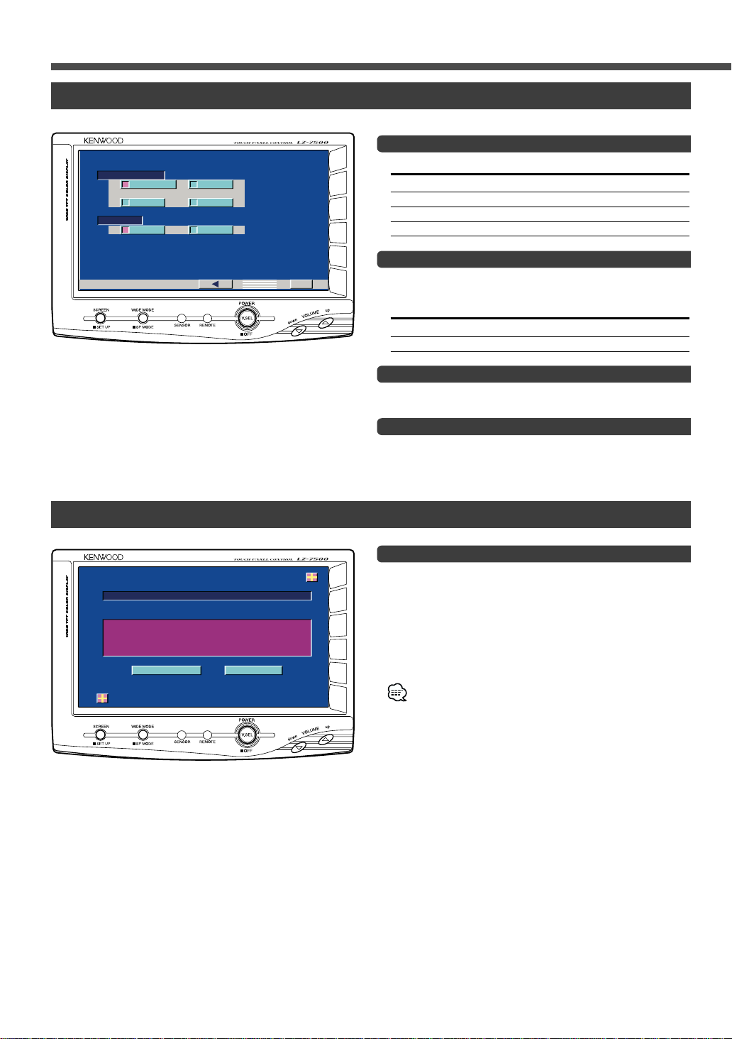
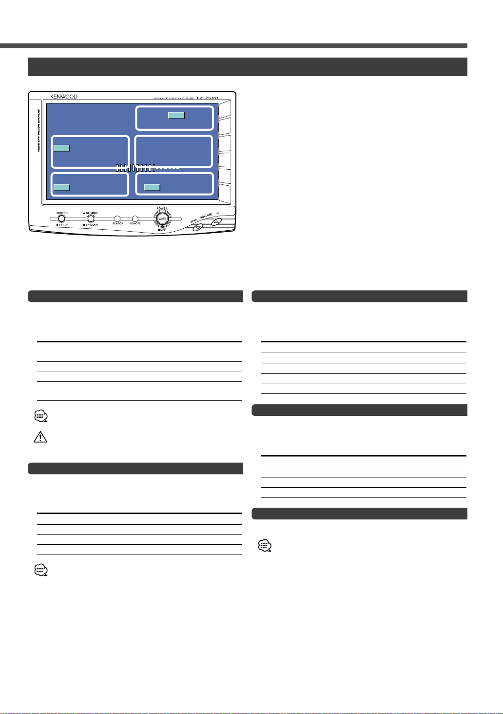
The illustrations of the display and the panel appearing in this manual are examples used to explain more clearly how the
controls are used. Therefore, what appears on the display in the illustrations may differ from what appears on the display
on the actual equipment, and some of the illustrations on the display may represent something impossible in actual
operation.
Before Use ..........................................................2
•Contents
•Safety Precaution
Operation............................................................3
Basic Operation ........................................................3
•Power
•Switching the Monitor’s Picture <VS>
•Volume <VOL>
•Switching the Video Screen Mode <WD>
•Switching the Speaker Mode <SP>
Screen Control Screen..............................................4
•Adjusting the Picture Quality
Setup Menu Screen ..................................................4
•Select the Setup Menu Screen
•Select the System Setup Screen
•Select the Touch Panel Adjustment Screen
•Exit the Setup Menu Screen
System Setup Screen-1 ............................................5
•Setting the Navigation Mode <NAV>
•Setting the AV IN-1 Mode <VD1>
•Setting the AV IN-2 Mode <VD2>
•Setting the Camera Mode <CAMERA/VIDEO>
•Switching to the System Setup Screen -2
•Exit the System Setup Screen
System Setup Screen-2 ............................................6
•Setting the AV Output Mode <AV OUT>
•Touch Sensor Tone <BEEP>
•Return to the System Setup Screen -1
•Exit the System Setup Screen
Touch Panel Adjustment Screen ............................6
•Touch Panel Adjustment
On Screen Control Mode..........................................7
•Switching the Monitor’s Picture [VS]
•Switching the Video Screen Mode [WD]
•Switching the Speaker Mode [SP]
•Setting the AV Output Mode [AV]
•Exit the On Screen Mode
Installation....................................................................8
Troubleshooting Guide .............................................12
Specifications ............................................................12
Safety Precaution
To prevent injury and/or fire, take the following precautions:
•Ensure that the unit is securely installed. Otherwise it may fly out of place during collisions and other jolts.
•When extending the ignition or ground cables, make sure to use automotive-grade cables or other cables with an area of
0.75mm2(AWG18) or more to prevent wire deterioration and damage to the wire coating.
•To prevent short circuits, never put or leave any metallic objects (e.g., coins or metal tools) inside the unit.
•If the unit starts to emit smoke or strange smells, turn off the power immediately and consult your Kenwood dealer
•Do not touch the liquid crystal fluid if the LCD is damaged or broken due to shock. The liquid crystal fluid may be
dangerous to your health or even fatal.
If the liquid crystal fluid from the LCD contacts your body or clothing, wash it off with soap immediately.
To prevent damage to the machine, take the following precautions:
•Make sure to ground the unit to a negative 12V DC power supply.
•Do not open the covers of the unit.
•Do not install the unit in a spot exposed to direct sunlight or excessive heat or humidity. Also avoid places with too much
dust or the possibility of water splashing.
•Do not subject the monitor unit to excessive shock, as it is a piece of precision equipment.
•When replacing a fuse, only use a new one with the prescribed rating. Using a fuse with the wrong rating may cause your
unit to malfunction.
•To prevent short circuits when replacing a fuse, first disconnect the wiring harness.
•Do not use any screws except for the ones provided. The use of improper screws might result in damage to the main
unit.
•You cannot view video pictures whilst the vehicle is moving. To enjoy video pictures, find a safe place to park and engage
the parking brake.
If you experience problems during installation, consult your Kenwood dealer.
NOTE
2CAUTION
2WARNING
Contents
LZ-7500(W)_EFG_01 02.2.15 10:13 AM Page 2

English - 3
Operation
Power
Turning on the power
Press the [V.SEL] button.
Turning off the power (Stand by mode)
Press the [V.SEL] button for at least 1 second.
Switching the Monitor’s Picture <VS>
Press the [V.SEL] button.
Each time the button is pressed the monitor’s picture
switches as follows:
Display Picture
"NAV" Navigation (During “NAV” set to “RGB” or
“AV IN1”)
"VD1" Video 1 (During “VD1” set to “AV-IN1”)
"VD2" Video 2 (During “VD2” set to “AV-IN2”)
"CAM" Video 3 (During “CAMERA/VIDEO” set to
“VD”)
For “NAV”, “VD” and “CAMERA/VIDEO” setting, refer to
<System Setup Screen> (Page 5).
You cannot view video pictures whilst the vehicle is moving. To
enjoy video pictures, find a safe place to park and engage the
parking brake.
Volume <VOL>
Increasing Volume:
Press the [up] button.
Decreasing Volume:
Press the [down] button.
Switching the Video Screen Mode <WD>
Press the [WIDE MODE] button.
Each time the button is pressed the screen mode
switches as follows:
Display Setting
"FULL" Full screen mode
"ZOOM" Zoom screen mode
"JUST" Just screen mode
"NORMAL" Normal screen mode
You cannot operate when the navigation picture is displayed.
Switching the Speaker Mode <SP>
Press the [WIDE MODE] button for at least 1 second.
Each time the button is pressed for at least 1 second the
built-in speaker mode switches as follows:
Display Setting
"NORMAL" Sound with monitor picture
"NAV" Sound with navigation picture
"VIDEO1" Sound with video 1 picture
"VIDEO2" Sound with video 2 picture
"OFF" Built-in speaker is turned off
V.SEL down
WIDE MODE up
;;;
;;;
yyy
yyy
;;;
;;;
yyy
yyy
;;;
;;;
• JUST
• NORMAL • FULL
• ZOOM
;;;
;;;
yyy
yyy
Screen Mode
NORMA
LOV
FULL
NORMA
LL
SP
WD
AV
VD1
VS
Basic Operation
LZ-7500(W)_EFG_01 02.2.15 10:13 AM Page 3

4-English
Operation
Adjusting the Picture Quality
1Displaying the Screen Control Screen
Press the [SCREEN] button.
2Setting
Touch the [2] or [3] button.
Item Touch Setting
TIN [ 3]Stronger green level
[ 2]Stronger red level
COL [ 3]Deeper colour
[ 2]Paler colour
CONT [ 3]Stronger contrast
[ 2]Less contrast
BLK [ 3]Less black level
[ 2]Stronger black level
DIM [ 3]Brighter screen
[ 2]Darker screen
•The [ TIN ] and [ COL ] cannot be adjusted for the RGB-
navigation picture or the setup screen.
•The [ TIN ] cannot be adjusted for the picture of PAL.
•Separate picture quality settings can be stored for the video
and navigation screens.
As regards [DIM] (Dimmer) adjustment:
There is no connection with the vehicle’s
illumination switch. (A dimmer sensor is installed
facing the front of monitor unit for light detection).
3Exit the Screen Control Screen
Touch the [OK] button.
If you make no operation for 10 seconds, the screen
control screen is automatically canceled.
SCREEN
TIN
COL
OK
BLK
CONT
DIM
SCREEN
SCREEN
RTN
SETUP
SYSTEM TOUCH
Screen Control Screen
Setup Menu Screen
Select the Setup Menu Screen
Press the [SCREEN] button for at least 1 second.
Setup Menu Screen is displayed.
Select the System Setup Screen
Touch the [SYSTEM] button.
System Setup Screen is displayed.(Page 5)
Select the Touch Panel Adjustment Screen
Touch the [TOUCH] button.
Touch Panel Adjust Screen is displayed.(Page 6)
Exit the Setup Menu Screen
Touch the [RTN] button.
If you cannot selected a setup menu item. Press the
[SCREEN] button for at least 2 second, the touch panel
position settings are reset to the factory defaults.
Dimmer sensor
LZ-7500(W)_EFG_01 02.2.15 10:13 AM Page 4

Setting the Navigation Mode <NAV>
Touch Setting
[7RGB] It becomes the RGB-image mode setting.
Operate the V.SEL button when the RGB-
image from the navigation unit connected to
<NAV I/F> terminal is shown on the
monitor.
[7AV-IN1] It becomes the composite--image mode
setting. Operate the V.SEL button when the
composite-image from the navigation unit
connected to <AV IN-1> terminal is shown on
the monitor.
[7OFF] It becomes the off mode setting. Use this
setting when there’s nothing connected to
the <NAV I/F> or <AV IN-1> terminal.
Setting the AV IN-1 Mode <VD1>
Touch Setting
[7AV-IN1] It becomes the video mode setting. Operate
the V.SEL button when the image from the
device connected to <AV IN-1> terminal is
shown on the monitor.
[7OFF] It becomes the OFF mode setting.Use this
setting when there’s nothing connected to
the <AV IN-1> terminal.
If you select "AV-IN 1", "NAV" setting is changed to "RGB".
Setting the AV IN-2 Mode <VD2>
Touch Setting
[7AV-IN2] It becomes the video mode setting. Operate
the V.SEL button when the image from the
device connected to <AV IN-2> terminal is
shown on the monitor.
[7OFF] It becomes the off mode setting.Use this
setting when there’s nothing connected to
the <AV IN-2> terminal.
English - 5
Setting the Camera Mode
<
CAMERA/VIDEO
>
Touch Setting
[7AUTO] It becomes the Rear view camera mode
setting. When the reverse sensor cable is
powered up, the monitor image is switched
to the image of the device connected to the
<CAMERA VIDEO IN> terminal.
[7VD] It becomes the video mode setting. Operate
the V.SEL button when the image from the
device connected to <CAMERA VIDEO IN>
terminal is shown on the monitor.
[7OFF] It becomes the off mode setting.Use this
setting when there’s nothing connected to
the <CAMERA VIDEO IN> terminal.
Switching to the System Setup Screen -2
Touch the [ 3] button.
Exit the System Setup Screen
Touch the [RTN] button.
Return to the setup menu screen.
RTN
SYS EMT
VD2
AV- IN2 OFF
AV- IN1 OFF
NAV
VD1
AV- IN1 OFF
CVIDEOAME AR/
AUTO VD
RGB
OFF
System Setup Screen-1
LZ-7500(W)_EFG_01 02.2.15 10:14 AM Page 5

6-English
Operation
Setting the AV Output Mode <AV OUT>
Touch Setting
[7NORMAL] Picture/sound with monitor picture
[7NAV] Navigation Sound
[7VD1] Picture/sound from <AV IN-1> terminal
[7VD2] Picture/sound from <AV IN-2> terminal
Touch Sensor Tone <BEEP>
Setting the operation check sound (beep sound)
ON/OFF.
Touch Setting
[7ON] Touch sensor tone is turned on
[7OFF] Touch sensor tone is turned off
Return to the System Setup Screen -1
Touch the [ 2] button.
Exit the System Setup Screen
Touch the [RTN] button.
Return to the setup menu screen.
RTN
SYS EMT
AV-OUT
VD1 VD2
BEEP
NAVNORM
ON OFF
RESETCANCEL
TOUCH PANEL ADJUST
Please Touch
the Ce ter of
the Bu ton in
Lef t -Bot tom Corner
n
tthe
Touch Panel Adjustment
The touch panel can be adjusted if the position
touched and the operation performed do not match.
Accurately touch the mark at the lower left.
Accurately touch the mark at the upper right.
When the mark at the upper right is touched, the
adjustment is completed and the system setup menu
screen reappears.
•If the [ CANCEL ] button is touched without touching the
button at the lower left, the adjustment is cancelled and the
screen that was set before switching to the system setup
menu reappears.
•If the [ CANCEL ] button is touched after touching the button
at the lower left, the button at the lower left reappears.
•If the [ RESET ] button is touched, the settings are reset to
the factory defaults and the setup menu screen reappears.
2
1
System Setup Screen-2
Touch Panel Adjustment Screen
LZ-7500(W)_EFG_01 02.2.15 10:14 AM Page 6

Switching the Monitor’s Picture [VS]
Touch the C part.
Each time the C part is touched the monitor’s picture
switches as follows:
Display Picture
"NAV" Navigation (During “NAV” set to “RGB” or
“AV IN1”)
"VD1" Video 1 (During “VD1” set to “AV-IN1”)
"VD2" Video 2 (During “VD2” set to “AV-IN2”)
"CAM" Video 3 (During “CAMERA/VIDEO” set to
“VD”)
For “NAV”, “VD” and “CAMERA/VIDEO” setting, refer to
<System Setup Screen> (Page 5).
You cannot view video pictures whilst the vehicle is moving. To
enjoy video pictures, find a safe place to park and engage the
parking brake.
Switching the Video Screen Mode [WD]
Touch the A part.
Each time the A part is touched the screen mode
switches as follows:
Display Setting
"FULL" Full screen mode
"ZOOM" Zoom screen mode
"JUST" Just screen mode
"NORMAL" Normal screen mode
You cannot operate when the navigation picture is displayed.
English - 7
Switching the Speaker Mode [SP]
Touch the B part.
Each time the B part is touched the built-in speaker
mode switches as follows:
Display Setting
"NORMAL" Sound with monitor picture
"NAV" Sound with navigation picture
"VIDEO1" Sound with video1 picture
"VIDEO2" Sound with video2 picture
"OFF" Switch off the built-in speakers
Setting the AV Output Mode [AV]
Touch the E part.
Each time the E part is touched the AV output mode
switches as follows:
Display Setting
"NORMAL" Picture/sound with monitor picture
"NAV" Navigation Sound
"VIDEO1" Picture/sound from <AV IN-1> terminal.
"VIDEO2" Picture/sound from <AV IN-2> terminal.
Exit the On Screen Mode
Touch the D part.
If you make no operation for 10 seconds, the On screen
control mode is automatically canceled.
NORMA
LOV
FULL
NORMA
LL
SP
WD
AV
VD1
VS
A
BE
C
On Screen Control Mode
D
When the current setting information is displayed on the screen, touching a dotted line will enable operation of
each of the following items:
LZ-7500(W)_EFG_01 02.2.15 10:14 AM Page 7

8-English
Installation
Accessories
A
BE
F
D
To prevent short circuits, remove the key from the
ignition and disconnect the ·terminal of the battery.
Make the proper input and output cable connections
for each unit.
Connect the wiring harness cables in the following
order: ground, ignition.
Connect the wiring harness connector to the unit.
Install the unit in your car.
Reconnect the ·terminal of the battery.
•This product is intended for use with 12V DC negative
ground power only. Do not connect it to any other power
supply
•To prevent shorting, disconnect the battery cable from
the negative terminal of the battery during installation.
•Be sure to firmly stabilise this product. Do not install it in
a location which is not stable.
•Follow the installation and wiring procedures described
in this manual. Improper wiring or modified installation
can not only result in malfunction or damage to the unit
but may also result in an accident.
•Do not install the unit in the following locations.
•Alocation which interferes with the operation of the
air bag system.
•Alocation which is not made of plastic.
\Installing on leather, wood or cloth may damage
the surface.
•Alocation subject to direct sunlight, subject to the air
from the air conditioner, or subject to moisture or high
temperature.
\ This may cause deformation of the monitor unit.
•Be sure to use the supplied screws for installation.
Using screws longer than those supplied may destroy
parts inside the unit causing it to smoke. Using screws
shorter than those supplied may cause the unit to come
looks from the installation bracket.
•If you are not going to install the unit using the supplied
monitor stand, be sure to use a commercially available
monitor stand. (Mounting holes for such a stand are
located on the bottom of the monitor unit.)
•If your car's ignition does not come with an ACC
position, connect the ignition cables to a power source
that can be turned on and off with the ignition key. If you
connect the ignition wire to a power source that receives
a constant voltage supply, as with battery cables, the
battery may die.
•If the fuse blows, first make sure that the cables have
not caused a short circuit, then replace the old fuse with
one with the same rating.
•Do not let unconnected cables or terminals touch metal
on the car or anything else conducting electricity. To
prevent short circuits do not remove the caps from
unused terminals or from the ends of the unconnected
cables.
•After the unit is installed, check whether the brake
lamps, blinkers, wipers, etc. on the car are working
properly.
•Insulate unconnected cables with vinyl tape or other
similar material.
•Thoroughly wipe away oil and other dirt from the
installation surface. Please avoid installation on uneven
surfaces.
2CAUTION
2WARNING
6
5
4
3
2
1
Installation Procedure
G
H
(Ø4 x 12 mm)
(Ø4 x 16 mm)
I
The use of any accessories except for those provided might result in damage to the unit. Make sure only to use the
accessories shipped with the unit, as shown above.
C
LZ-7500(W)_EFG_01 02.2.15 10:14 AM Page 8

English - 9
Connection
ディスプレイユニット電源 NAVI/F
VIDEO
CAMERA VIDEO IN
L- AUDIO - R
TO NAVIGATION UNITTO
MONITOR UNIT
POWER
AV OUT
3 A
+12V
+12V
1
2
AV IN
L-AUDIO-RVIDEO
VIDEO
CAMERA VIDEO IN
L- AUDIO - R
TO NAVIGATION UNITTO
MONITOR UNIT
POWER
AV OUT
Accessory B
Ignition cable (Red) ª12V
Parking sensor cable (Green)
For the sake of safety, be sure
to connect the parking sensor.
2CAUTION
Ignition key switch
Car fuse box (Main fuse)
ACC
Ground cable (Black) ·(To car chassis)
Battery
Monitor Unit
Fuse (3A)
Reverse sensor cable (Pink)
<When the Rear view camera
is connected>
Audio/Visual input 1
•Visual input (Yellow)
•Audio left input (White)
•Audio right input (Red)
Audio/Visual input 2
•Visual input (Yellow)
•Audio left input (White)
•Audio right input (Red)
Audio/Visual Output
•Visual output (Yellow)
•Audio left output (White)
•Audio right output (Red)
Rear view
camera input
Navigation Unit
Connection cable
(Provided with the KENWOOD
Navigation Unit)
Accessory A
Video Box Unit
Bundle cables with the
clamper (Accessory I)
Accessory C
LZ-7500(W)_EFG_01 02.2.15 10:14 AM Page 9

10 - English
Installation
Installation location and cleaning
Select for installation a location where the stand can be placed
completely horizontal or where the front edge of the support
(petal-shaped part) can be attached horizontally as shown in
Figure A.
Do not install in locations where the entire support is at a
diagonal such as in Figure Bor where the monitor unit is
facing down such as in Figure C.
Thoroughly wipe away and dust or grease from the installation
location using a cloth which has been soaked in a neutral
cleaning agent and wrung out. Attach the stand after allowing
the installation location to dry.
2CAUTION
;;;;;;;;;;;
;;;;;;;;;;;
;;;;;;;;;;;
;;;;;;;;;;;
;;;;;;;;;;;
;;;;;;;;;;;
;;;;;;;;;;;
;;;;;;;;;;;
;;;;;;;;;;;
;;;;;;;;;;;
;;;;;;;;;
;;;;;;;;;
;;;;;;;;;
;;;;;;;;;
;;;;;;;;;
;;;;;;;;;
;;;;;;;;;
;;;;;;;;;
;;;;;;;;;
;;;;;;;;;
;;;;;;;;;
;;;;;;;;
;;;;;;;;
;;;;;;;;
;;;;;;;;
;;;;;;;;
;;;;;;;;
;;;;;;;;
;;;;;;;;
;;;;;;;;
ABC
Bend the stand support to conform to the shape of the
installation location.
Adjust the shape of the support so that there is no rattling
or gap when the stand is placed on the support.
Peel off the protective strip from the double-sided tape on
the bottom of the stand and securely attach the stand.
•Do not attach the double-sided tape more than once or
touch the adhesive with your fingers as this will weaken
its adhesive strength.
•If the temperature of the surface of the installation
location is low, warm it up using a heater or other means
before attaching the stand. Low temperature may
weaken the adhesive strength of the tape.
•The supplied stand is specially intended for this product.
Do not use it with another monitor.
Secure the stand using the supplied tapping screw
(Accessory H).
After attaching the stand, allow it to sit undisturbed for 24
hours.
Take care not to apply any force to the stand during this
time.
Fully loosen the installation screws, align the slit on the
rear of the unit with the installation shoe and slide the
monitor unit onto the stand.
Adjust the height, horizontal angle and vertical angle of the
monitor and securely tighten the installation screws.
You can also adjust the monitor unit's forward position by
loosening the angle adjustment knobs and adjusting the
angle of the monitor unit's installation stand.
8
7
6
5
4
2CAUTION
3
2
1
Installation for Monitor Unit
Accessory E
Accessory HProtective strip
Tighten
Loosen
Installation surface
Tighten
Loosen
LZ-7500(W)_EFG_01 02.2.15 10:14 AM Page 10

English - 11
Installation for Video Box Unit
■Securing to audio board
Accessory G
Accessory D
Removed the screw
Accessory F
Remove the screws on both sides that are already
attached to Video Box Unit.
Use the screws removed in step 1 and attached screws
(Accessory G) to fix the bracket (Accessory D) onto both
sides of Video Box Unit.
Use screws (Accessory F) to fix Video Box Unit onto an
audio board or another.
3
2
1
LZ-7500(W)_EFG_01 02.2.15 10:14 AM Page 11

12 - English
Troubleshooting Guide
What might appear to be a malfunction in your unit may just be the result of slight misoperation or
miswiring. Before calling service, first check the following table for possible problems.
SOLUTIONPOSSIBLE CAUSEPROBLEM
The power does not turn on. The fuse has blown. After checking for short circuits in the cables,
replace the fuse with one having the same rating.
No ACC position on vehicle ignition. Connect the same cable to the ignition as the
battery cable.
No video picture appears. The unit is not connected to the
parking brake detection switch.
Make proper connections according to
”Connection“.
The parking brake is not engaged. For safety reasons no video picture are displayed
while the vehicle is moving. Engaging the parking
brake will cause picture to be displayed.
The screen is dark. The unit is in a location where
temperature is low.
If the temperature of the monitor unit drops, the
screen may appear darker when power is first turned
on due to the characteristics of a liquid crystal panel.
Wait a while after turning power on for the
temperature to rise. Normal brightness will return.
Specifications
Specifications subject to change without notice.
Monitor Unit
Screen size ......................................................................................................................6.95 inches wide
154.1(W) x 86.6(H) x 176.7(Diagonal) mm
6-1/16(W) x 3-7/16(H) inches
Display system ..................................................................................................Transparent TN LCD panel
Drive system ......................................................................................................TFT active matrix system
Number of pixels..............................................................................336,960 pixels (480 H x 234 V x RGB)
Effective pixels ..............................................................................................................................99.99%
Pixel arrangement ..............................................................................................RGB striped arrangement
Back lighting ..................................................................................................................Cold cathode tube
Speaker power ....................................................................................................................1 W (40 Ø x 1)
Video Box Unit
Colour system ..........................................................................................................................NTSC/PAL
External video input level (RCA jacks) ............................................................................1 ± 0.1 Vp-p/ 75 Ω
External audio input level (RCA jacks) ........................................................................................1 V/ 22 KΩ
Video output level (RCA jacks)........................................................................................1 ± 0.1 Vp-p/ 75 Ω
Audio output level (RCA jacks) ..............................................................................................500 mV/ 1 KΩ
Analog RGB input ................................................................................................................0.7 Vp-p/ 75 Ω
General
Operating voltage ......................................................................................................14.4 V DC (11 - 16 V)
Consumed Power ..............................................................................................................................14 W
Operational temperature range ..........................................................................................–10°C to +60°C
Storage temperature range ................................................................................................–30°C to +80°C
Size
(Monitor unit) ................................................................................................189(W) x 131(H) x 37(D) mm
7-7/16(W) x 5-3/16(H) x 1-7/16(D) inches
(Video box unit) ..............................................................................................167(W) x 38(H) x 152(D) mm
6-9/16(W) x 1-1/2(H) x 6(D) inches
Mass
(Monitor unit) ....................................................................................................................580 g(1.28 LBS)
(Video box unit)..................................................................................................................620 g(1.37 LBS)
Although the effective pixels for the liquid crystal panel is given as 99.99% or more, 0.01% of pixels may not light or
may light incorrectly.
LZ-7500(W)_EFG_01 02.2.15 10:14 AM Page 12

LZ-7500(W)_EFG_01 02.2.15 10:14 AM Page 13

14 - Français
Avant l’utilisation
Les illustrations de l’affichage et du panneau apparaissant dans ce manuel sont des exemples utilisés pour expliquer avec
plus de clarté comment les commandes sont utilisées. Il est donc possible que les illustrations d’affichage puissent être
différentes de ce qui réellement affiché sur l’appareil et aussi que certaines illustrations représentent des choses
impossibles à réaliser en cours de fonctionnement.
Avant l’utilisation ............................................14
•Table des matières
•Précautions de sécurité
Opération..........................................................15
Opération de base ..................................................15
•Alimentation
•Commutation de l’image du moniteur <VS>
•Volume <VOL>
•Sélection du mode d’écran Vidéo <WD>
•Commuter le mode haut-parleur <SP>
Ecran de commande par l’écran ............................16
•Réglage de Qualité de l'image
Ecran de menu de configuration ..........................16
•Sélection de l’écran du menu de configuration
•Sélection de l’écran de paramétrage du système
•Sélection de l’écran réglage de l’écran tactile
•Sortez de l'écran du menu de configuration
Ecran de paramétrage du système-1 ....................17
•Réglage du mode de navigation <NAV>
•Réglage du mode AV IN-1 <VD1>
•Réglage du mode AV IN-2 <VD2>
•Réglage du mode Camera <CAMERA/VIDEO>
•Passer à l’écran de paramétrage du système-2
•Sortez de l’écran de paramétrage du système
Ecran de paramétrage du système-2 ....................18
•Réglage du mode de sortie AV <AV OUT>
•Tonalité capteur tactile <BEEP>
•Retour à l’écran de paramétrage du système-1
•Sortez de l’écran de paramétrage du système
Ecran de réglage de l’écran tactile ........................18
•Ajustement des touches
Mode de contrôle à l’écran ....................................19
•Commutation de l’image du moniteur [VS]
•Sélection du mode d’écran Vidéo [WD]
•Commuter le mode haut-parleur [SP]
•Réglage du mode de sortie AV [AV]
•Sortez de mode de contrôle à l’écran
Installation..................................................................20
Guide de depannage .................................................24
Spécifications ............................................................24
Précautions de sécurité
Pour éviter toute blessure et/ou incendie, veuillez prendre les précautions suivantes:
•Assurez-vous que l’appareil soit corectement installé. Sinon il risquerait d’être déplacé en cas de collisions ou de cahots.
•Si vous prolongez un câble d’alimentation, de batterie ou de masse, assurez vous d’utiliser un câble pour automobile ou
un câble avec une section de 0,75mm2(AWG18) afin d’éviter tout risque de détérioration ou d’endommagement de
l’isolation des câbles.
•Pour éviter les court-circuits, ne jamais mettre ou laisser d’objets métalliques (comme une pièce de monnaie ou un outil )
à l’intérieur de l’appareil.
•Si l’appareil émet de la fumée ou une odeur bizarre, mettez immédiatement l’appareil hors tension et consultez un
revendeur Kenwood.
•Ne touchez pas le cristal liquide si l’affichage LCD était endommagé ou cassé à cause d’un choc. Le cristal liquide peut
être dangereux pour votre santé et même mortel.
Si le cristal liquide de l’affichage LCD entrait en contact avec votre corps ou un vêtement, lavez-le immédiatement avec du
savon.
Pour éviter tout dommage à l’appareil, veuillez prendre les précautions suivantes:
•Assurez-vous de mettre l’appareil à la masse sur une alimentation négative de 12V CC.
•N’ouvrez pas le couvercle de l’appareil.
•N’installez pas l’appareil dans un endroit exposé directement à la lumière du soleil, à une chaleur excessive ou à
l’humidité. Evitez aussi les endroits trop poussiéreux et où l’appareil risque d’être éclaboussé.
•Ne faites pas subir de chocs excessifs à la façade car elle fait partie d’un équipement de précision.
•Lors du remplacement d’un fusible, utilisez seulement un fusible neuf avec la valeur indiquée. L’utilisation d’un fusible
d’une valeur différente peut être la cause d’un mauvais fonctionnement de votre appareil.
•Pour éviter les courts-circuits lors du remplacement d’un fusible, déconnectez d’abord le faisceau de câbles.
•Pendant l’installation, n’utilisez aucunes autres vis que celles fournies. L’utilisation de vis incorrectes pourrait
endommager l’appareil.
•Il est impossible de regarder des images vidéo pendant que le véhicule se déplace. Pour apprécier les images vidéo, garer
le véhicule dans un endroit sûr et tirer le frein à main.
Si vous rencontrez des problèmes pendant l’installation, consultez votre revendeur Kenwood.
REMARQUE
2ATTENTION
2AVERTISSEMENT
Table des matières
LZ-7500(W)_EFG_01 02.2.15 10:14 AM Page 14

Opération
Français - 15
Alimentation
Mise sous tension
Appuyer sur la touche [V.SEL].
Mise hors circuit (mode Stand by)
Appuyer sur la touche [V.SEL] pendant au moins 1
secondes.
Commutation de l’image du moniteur <VS>
Appuyez sur la touche [V.SEL].
Chaque fois que l’on appuie sur la touche, l'image du
moniteur change de la manière suivante:
Affichage Image
"NAV" Navigation (Pendant “NAV” installé sur
“RGB” ou “AV IN1”)
"VD1" Video 1 (Pendant “VD1” installé sur “AV-
IN1”)
"VD2" Video 2 (Pendant “VD2” installé sur “AV-
IN2”)
"CAM" Video 3 (Pendant “CAMERA/VIDEO”
installé sur “VD”)
Pour la configuration de“NAV”, “VD” et “CAMERA/VIDEO”,
rapportez-vous au <Ecran de paramétrage du système>(Page 17).
Il est impossible de regarder des images vidéo pendant que le
véhicule se déplace. Pour apprécier les images vidéo, garer le
véhicule dans un endroit sûr et tirer le frein à main.
Volume <VOL>
Augmenter le volume:
Appuyez sur la touche [up].
Baisser le volume:
Appuyez sur la touche [down].
Sélection du mode d’écran Vidéo <WD>
Appuyez sur la touche [WIDE MODE].
Chaque fois que l’on appuie sur la touche, le mode de
l'écran change de la manière suivante:
Affichage Réglage
"FULL" Mode Grand écran
"ZOOM" Mode de Zoom
"JUST" Uniquement mode écran
"NORMAL" Mode d'écran normal
Cette commande ne fonctionne pas lorsque l’image de
navigation est affichée.
Commuter le mode haut-parleur <SP>
Appuyez sur la touche [WIDE MODE] pendant au
moins 1 seconde.
Chaque fois que la touche est pressée pendant une
seconde minimum, le micro intégré change de mode
comme suit:
Affichage Réglage
"NORMAL" Son avec image du moniteur
"NAV" Son avec image de navigation
"VIDEO1" Son avec image de la vidéo 1
"VIDEO2" Son avec image de la vidéo 2
"OFF" Haut-parleur intégré éteint
V.SEL down
WIDE MODE up
;;;
;;;
yyy
yyy
;;;
;;;
yyy
yyy
;;;
;;;
• JUST
• NORMAL • FULL
• ZOOM
;;;
;;;
yyy
yyy
Mode d’écran
NORMA
LOV
FULL
NORMA
LL
SP
WD
AV
VD1
VS
Opération de base
LZ-7500(W)_EFG_01 02.2.15 10:14 AM Page 15

16 - Français
Opération
Réglage de Qualité de l'image
1Afficher l’écran de contrôle
Appuyer sur la touche [SCREEN].
2Réglage
Effleurez la touche [2] ou [3].
Elément Effleurer Réglage
TIN [ 3]Niveau de vert plus élevé
[ 2]Niveau de rouge plus élevé
COL [ 3]Couleur plus profonde
[ 2]Couleur plus pale
CONT [ 3]Niveau de contraste plus fort
[ 2]Moins de contraste
BLK [ 3]Noir moins élevé
[ 2]Niveau de noir plus élevé
DIM [ 3]Ecran plus clair
[ 2]Ecran plus sombre
•Le [ TIN ] et le [ COL ] ne peuvent être adaptés à l’image de
navigation RGB de l’écran d’installation.
•La teinte [ TIN ] ne peut pas être réglée pour une image du
type PAL.
•Des réglages de qualité d'image séparés peuvent être réglés
pour les écrans de commande de télévision, vidéo, et de
navigation.
En ce qui concerne l’ajustement [DIM]
(Interrupteur):
Il n’y a aucune connexion avec l’interrupteur
d’illumination du véhicule. (Un capteur est installé
face au moniteur pour détecter la lumière).
3Sortez de l'écran de commande par l’écran
Effleurez la touche [OK].
Si vous n’effectuez aucune opération pendant 10
secondes, l’écran de contrôle est annulé
automatiquement.
SCREEN
TIN
COL
OK
BLK
CONT
DIM
SCREEN
SCREEN
RTN
SETUP
SYSTEM TOUCH
Ecran de commande par l’écran
Ecran de menu de configuration
Sélection de l’écran du menu de configuration
Appuyez sur la touche [SCREEN] pendant au moins 1
seconde.
L’écran du menu de configuration est affiché.
Sélection de l’écran de paramétrage du système
Effleurez la touche [SYSTEM].
L’écran de de paramétrage du système est affiché.
(Page 17)
Sélection de l’écran réglage de l’écran tactile
Effleurez la touche [TOUCH].
L’écran réglage de l’écran tactile est affiché.(Page 18)
Sortez de l'écran du menu de configuration
Effleurez la touche [RTN].
Si vous ne pouvez pas sélectionner un point du menu
d’installation, pressez la touche [SCREEN] pendant 2
secondes minimum, les installations de position sont
annulées au profit de la configuration par défaut.
Détecter la lumière
LZ-7500(W)_EFG_01 02.2.15 10:14 AM Page 16

Français - 17
Réglage du mode de navigation <NAV>
Effleurer Réglage
[7RGB] Apparaît l’installation du mode d’image RGB.
Actionnez le bouton V.SEL lorsque l’image
RGB issue de l’unité de navigation
connectée au terminal <NAV I/F> est
affichée sur le moniteur.
[7AV-IN1] Apparaît l’installation du mode image
composite. Actionnez le bouton V.SEL
lorsque l’image composite issue de l’unité de
navigation connectée au terminal <AV IN-1>
est affichée sur le moniteur.
[7OFF] Apparaît le mode d’installation hors
connexion. Utilisez cette installation lorsque
aucun élément n’est connecté au terminal
<NAV I/F> ou <AV IN-1>.
Réglage du mode AV IN-1 <VD1>
Effleurer Réglage
[7AV-IN1] Ceci devient le réglage de mode vidéo.
utilisez la touche V.SEL lorsque l'image de
l'appareil connecté à la borne <AV IN-1> est
affichée sur le moniteur.
[7OFF] Ceci devient le réglage de mode OFF.
Utiliser ce réglage lorsqu'il n'y a rien
connecté à la borne <AV IN-1>.
Si vous sélectionnez "AV-IN 1", la configuration "NAV" est
modifiée et remplacée par "RGB".
Réglage du mode AV IN-2 <VD2>
Effleurer Réglage
[7AV-IN2] Ceci devient le réglage de mode vidéo.
utilisez la touche V.SEL lorsque l'image de
l'appareil connecté à la borne <AV IN-2> est
affichée sur le moniteur.
[7OFF] Ceci devient le réglage de mode OFF.
Utiliser ce réglage lorsqu'il n'y a rien
connecté à la borne <AV IN-2>.
Réglage du mode Camera <CAMERA/VIDEO>
Effleurer Réglage
[7AUTO] Apparaît le mode d’installation la rétro-
camera. Lorsque le câble du capteur inversé
est alimenté, l’image du moniteur est
branchée sur l’image du dispositif connecté
au terminal <CAMERA VIDEO IN>.
[7VD] Ceci devient le réglage de mode vidéo.
utilisez la touche V.SEL lorsque l'image de
l'appareil connecté à la borne <CAMERA
VIDEO IN> est affichée sur le moniteur.
[7OFF] Ceci devient le réglage de mode OFF.
Utiliser ce réglage lorsqu'il n'y a rien
connecté à la borne <CAMERA VIDEO IN>.
Passer à l’écran de paramétrage du système-2
Effleurez la touche [ 3].
Sortez de l’écran de paramétrage du système
Effleurez la touche [RTN].
Retour à l’écran de menus de réglage.
RTN
SYS EMT
VD2
AV- IN2 OFF
AV- IN1 OFF
NAV
VD1
AV- IN1 OFF
CVIDEOAME AR/
AUTO VD
RGB
OFF
Ecran de paramétrage du système-1
LZ-7500(W)_EFG_01 02.2.15 10:14 AM Page 17

18 - Français
Opération
Réglage du mode de sortie AV <AV OUT>
Effleurer Réglage
[7NORMAL] Image/son avec image du moniteur
[7NAV] Son de navigation
[7VD1] Image/son du terminal <AV IN-1>
[7VD2] Image/son du terminal <AV IN-2>
Tonalité capteur tactile <BEEP>
Activer/Désactiver le signal sonore de contrôle
d'opération (bip).
Effleurer Réglage
[7ON] La tonalité de détection de touche est
activée.
[7OFF] La tonalité de détection de touche est
désactivée.
Retour à l’écran d’installation du système -1
Effleurez la touche [ 2].
Sortez de l’écran d’installation du système
Effleurez la touche [RTN].
Retour à l’écran de menus de réglage.
RTN
SYS EMT
AV-OUT
VD1 VD2
BEEP
NAVNORM
ON OFF
RESETCANCEL
TOUCH PANEL ADJUST
Please Touch
the Ce ter of
the Bu ton in
Lef t -Bot tom Corner
n
tthe
Ajustement des touches
Le panneau à touchement peut être adapté si
l’endroit touché et l’opération effectuée ne
correspondent pas.
Toucher précisément la marque située en bas à
gauche.
Toucher précisément la marque située en haut à
droite.
Lorsque la marque en haut à droite est touchée,
l’ajustement est accompli et l’écran d’installation du
système réapparaît.
•Si la touche [ CANCEL ] est effectuée sans que le bouchon
en bas à droit soit touché, le réglage est annulé et l’écran
installé avant le passage au menu d’installation système
réapparaît.
•Si la touche [ CANCEL ] est effectuée après que le bouton en
bas à gauche soit touché, ce dernier réapparaît.
•Si la touche [ RESET ] est effectuée, les réglages sont
initialisés aux réglages d’usines et l’écran principal du
paramétrage système réapparaît.
2
1
Ecran de paramétrage du système-2
Ecran de réglage de l’écran tactile
LZ-7500(W)_EFG_01 02.2.15 10:14 AM Page 18

Français - 19
Commutation de l’image du moniteur [VS]
Toucher la partie C.
Chaque fois que la partie C est touchée, l’image à l’écran
se modifie comme suit:
Affichage Image
"NAV" Navigation (Pendant “NAV” installé sur
“RGB” ou “AV IN1”)
"VD1" Video 1 (Pendant “VD1” installé sur “AV-
IN1”)
"VD2" Video 2 (Pendant “VD2” installé sur “AV-
IN2”)
"CAM" Video 3 (Pendant “CAMERA/VIDEO”
installé sur “VD”)
Pour la configuration de“NAV”, “VD” et “CAMERA/VIDEO”,
rapportez-vous au <Ecran de paramétrage du système>
(Page 17).
Il est impossible de regarder des images vidéo pendant que le
véhicule se déplace. Pour apprécier les images vidéo, garer le
véhicule dans un endroit sûr et tirer le frein à main.
Sélection du mode d’écran Vidéo [WD]
Toucher la partie A.
Chaque fois que la partie A est touchée, le mode à
l’écran se modifie comme suit:
Affichage Réglage
"FULL" Mode Grand écran
"ZOOM" Mode de Zoom
"JUST" Uniquement mode écran
"NORMAL" Mode d'écran normal
Cette commande ne fonctionne pas lorsque l’image de
navigation est affichée.
Commuter le mode haut-parleur [SP]
Toucher la partie B.
Chaque fois que la partie B est touchée, le micro intégré
se modifie comme suit:
Affichage Réglage
"NORMAL" Son avec image du moniteur
"NAV" Son avec image de navigation
"VIDEO1" Son avec image de la vidéo 1
"VIDEO2" Son avec image de la vidéo 2
"OFF" Micro intégré éteint
Réglage du mode de sortie AV [AV]
Toucher la partie E.
Chaque fois que la partie E est touchée, le mode de
production AV se modifie comme suit:
Affichage Réglage
"NORMAL" Image/son avec image du moniteur
"NAV" Son de navigation
"VIDEO1" Image/son du terminal <AV IN-1>.
"VIDEO2" Image/son du terminal <AV IN-2>.
Sortez de mode de contrôle à l’écran
Toucher la partie D.
Si vous n’effectuez aucune opération pendant 10 secondes,
le mode de contrôle à l’écran est annulé automatiquement.
NORMA
LOV
FULL
NORMA
LL
SP
WD
AV
VD1
VS
A
BE
C
Mode de contrôle à l’écran
D
Lorsque les informations relatives à la configuration actuelle sont affichées à l’écran, le fait de toucher une ligne
en pointillés permettra de réaliser les points suivants:
LZ-7500(W)_EFG_01 02.2.15 10:14 AM Page 19

20 - Français
Installation
Accessoires
A
BE
F
D
Pour éviter les courts-circuits, retirez la clef de contact
et déconnectez la borne ·de la batterie.
Effectuez correctement les connexions d’entrée et
sortie de chaque appareil.
Connectez le faisceau de câbles dans l’ordre suivant:
masse, allumage.
Branchez le connecteur du faisceau à l’appareil.
Installez l’appareil dans votre voiture.
Reconnectez la borne ·de la batterie.
•Ce produit est destiné à être utilisé uniquement avec une
masse négative de 12 V CC. Ne le connectez pas à un
autre type d’alimentation.
•Pour éviter un court-circuit, débranchez le câble de la
batterie de la borne négative de la batterie pendant
l’installation.
•Assurez-vous de bien stabiliser ce produit. Ne l’installez
pas dans un endroit instable.
•Suivez les procédures d’installation et de câblage
décrites dans ce manuel. Un câblage incorrect ou une
installation modifiée peut provoquer non seulement un
mauvais fonctionnement ou endommager l’appareil,
mais aussi provoquer un accident.
•N’installez pas l’unité dans les endroits suivants.
•Des endroits qui gênent le fonctionnementdu
système d’air bag.
•Des endroits qui ne sont pas en matière plastique.
\Le fait de l’installer sur une surface en cuir, en
bois ou en tissu risque d’endommager la surface.
•Des endroits soumis aux rayons directs du soleil, à
l’air d’un climatiseur, ou des endroits humides ou des
endroits où régne une température élevée.
\Cela risque de provoquer une déformation du
moniteur.
•Assurez-vous d’utiliser les vis fournies pour
l’installation.
Le fait d’utiliser des vis plus longues que celles fournies,
risque de détruire des sections à l’intérieur de l’appareil
et de provoquer une émission de fumée. Le fait d’utiliser
des vis plus courtes que celles fournies, risque de
détacher l’appareil du support d’installation.
•Si vous n’allez pas installer l’appareil avec le support pour
moniteur fourni, assurez-vous d’utiliser un support de
moniteur disponible dans le commerce. (Des trous de
montage du support sont situés au fond du moniteur.)
•Si l’allumage de votre voiture n’a pas de position ACC,
connectez le câble d’allumage à une source
d’alimentation qui peut être mise sous et hors tension
avec la clef de contact. Si vous connectez le câble
d’allumage à une source d’alimentation constante,
comme un câble de batterie, la batterie risque de se
décharger.
•Si un fusible grille, assurez-vous d’abord que les câbles
n’ont pas causé de court-circuit puis remplacez le vieux
fusible par un nouveau de même valeur.
•Ne laissez pas des câbles non-connectés ou des prises
toucher les parties métalliques de la voiture ou autres
conducteurs électriques. Pour éviter, les courts-circuits,
ne retirez pas non plus les capuchons à l’extrémité des
câbles non-connectés ou des prises.
•Après avoir installé l’appareil, vérifiez si les feux de
freinage, les indicateurs, les clignotants, etc de la voiture
fonctionnent correctement.
•Isolez les câbles non-connectés avec un ruban adhésif en
vinyle ou autre matériel similaire.
•Essuyer à fond la poussière ou de la graisse de
l’emplacement d’installation à l’aide d’un chiffon imbibé
dans une solution de nettoyage neutre et essoré sec.
Fixer le socle après avoir séché l’emplacement
d’installation.
2ATTENTION
2AVERTISSEMENT
6
5
4
3
2
1
Procédure d’installation
G
H
(Ø4 x 12 mm)
(Ø4 x 16 mm)
I
L’utilisation d’accessoires autres que les accessoires fournis pourrait endommager l’appareil. Assurez-vous d’utiliser
les accessoires fournis, indiqués ci-dessus.
C
LZ-7500(W)_EFG_01 02.2.15 10:14 AM Page 20
Table of contents
Languages:
Other Kenwood Touchscreen manuals