(No.RA073<Rev.001>)1-7
2.2.7 Clone Mode
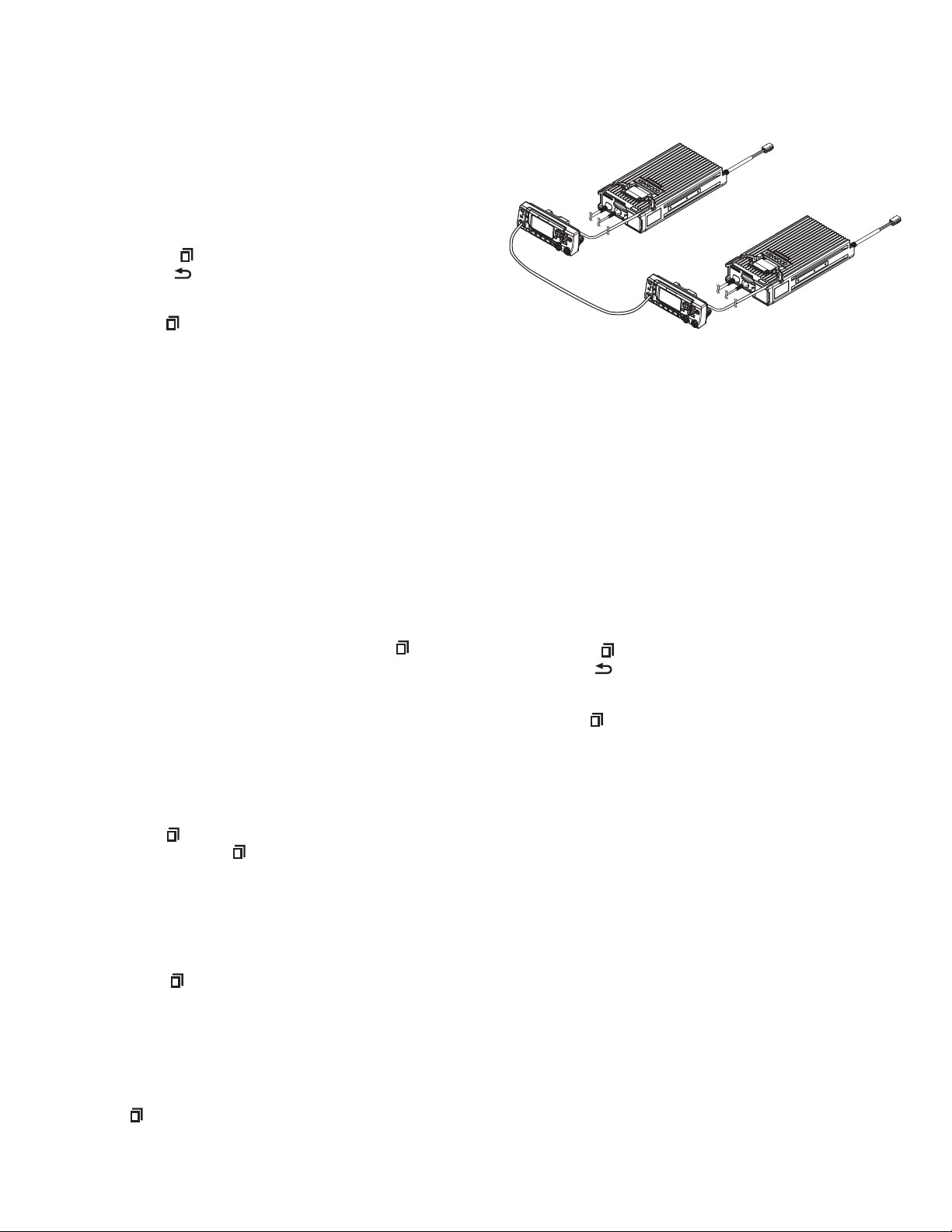
Programming data can be transferred from one transceiver to
another by connecting them via their modular microphone jacks.
The operation is as follows.
The following data cannot be cloned.
• Tuning data
• Embedded message with password
• ESN (Electronic Serial Number) data
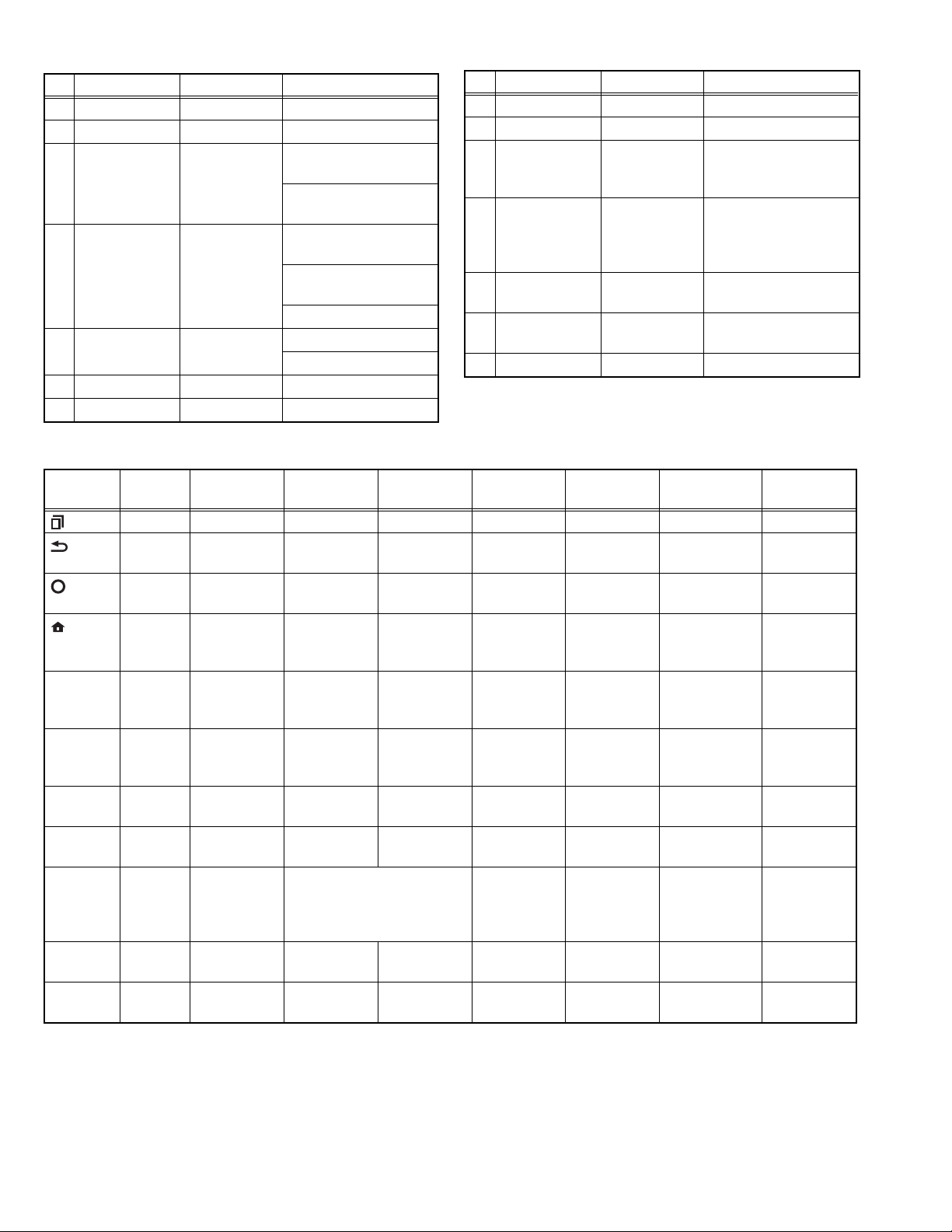
Key guide on the Clone/ Front Panel Programming
Password input screen.
• Confirm ([ ] key): The password confirmation
• Delete ([ ] key): Delete the latest digit from the current
password number (Press and hold to delete all password
numbers)
• Select([ ] key): Determine the latest digit of the password
number.
(1) In the source transceiver, enter the clone mode by using
section “2.2.2 How to Enter Each Mode”. When the Clone/
Front Panel Programming Password is set to the
transceiver, "Input Password" is displayed on the LCD.
If the password is not set, the transceiver displays "CLONE
MODE".
(2) When you enter the correct password, “CLONE MODE” is
displayed, the transceiver can be used as the cloning
source. The following describes how to enter the
password.
(3) There are two methods to enter the password as follows.
- How to enter the password using the MIC keypad;
If one of the keys 0 to 9 is pressed while the “Input
Password” is displayed, the password number is
displayed on the LCD.
Each press of the key shifts the display in order to the
left.
When you enter the password and press [ ] or [*] key,
“CLONE MODE” displayed if the entered password is
correct. If password is incorrect, “Input Password” is
redisplayed.
- How to enter password using the [] and [] keys;
If the [] / [] key is pressed while “Input Password” is
displayed, the Clone/ Front Panel Programming
Password input screen is displayed.
If the [] or [] key is pressed while the clone/ Front
Panel Programming Password input screen is displayed,
the number (0 to 9) blinks on the LCD. When you press
the [ ] key, currently selected number is determined. If
you press the [ ] key after entering password in this
procedure, “CLONE MODE” is displayed if entered
password is correct. If the password is incorrect, “Input
Password” is redisplayed.
(4) Power ON the target transceiver.
(5) Connecting the cloning cable (part No.E30-3382-05) to the
modular microphone jacks on the source and target.
(6) Press [ ] key on the source while the source displays
“CLONE MODE”. The data of the source is sent to the
target. While the target is receiving the data, “PROGRAM”
is displayed. When cloning of the data is completed, the
source displays “END”, and the target automatically
operates in the User mode. The target can then be
operated by the same program as the source.
(7) The other target can be continuously cloned. When the
[ ] key on the source is pressed while the source displays
“END”, the source displays “CLONE MODE”. Carry out the
operation in step (4) to (6).
Note:
• Cannot be cloned if the password (overwrite password) is
programmed to the target.
• “Model name” must be same to clone the transceiver.
Fig.2
2.2.8 Front Panel Programming Mode
If the Front Panel Programming Mode is used, the frequency or
other data of the conventional channel is rewritable only by the
transceiver.
Moreover, the conventional channel can be added.
The following setup items can be changed or added by
using the Front panel programming mode.
• RX/TX Frequency
• Channel Type
• Channel Spacing
• Decode QT/DQT/RAN/NAC, Encode QT/DQT/RAN/NAC
• Talkgroup ID List No.
• Transmit Power
• Channel Name
Key guide on the Clone/ Front Panel Programming
Password input screen.
• Confirm ([ ] key): The password confirmation
• Delete ([ ] key): Delete the latest digit from the current
password number (Press and hold to delete all password
numbers)
• Select ([ ] key): Determine the latest digit of the password
number.
2.2.8.1 How to enter the Front panel programming mode
Press the PF key which is assigned as “Panel Program” by the
FPU, or select the “Panel Program” which is assigned into the
Menu key by the FPU.
If the Clone/Front panel programming Password is not set to the
transceiver, "Panel Program" is displayed on the LCD. If the
Clone/Front panel programming Password is set to the
transceiver, "Panel Program" is displayed on the LCD when you
enter the correct password while “Input Password” is displayed.
2.2.8.2 Data Writing
Before moving to next Zone/Channel, “Keep This Change?”
appears on the LCD, if you select “OK”, the new data is written
to memory. If you select “Cancel”, the new data not be written;
the new data will be erased.
•The setup items for Front panel programming mode are as
follows.
NX-5700HB with
KCH-20R
NX-5700HB with
KCH-20R
Cloning cable
(E30-3382-05)