manuals.online logo
Brands
  1. Home
  2. •
  3. Brands
  4. •
  5. Kenwood
  6. •
  7. Transceiver
  8. •
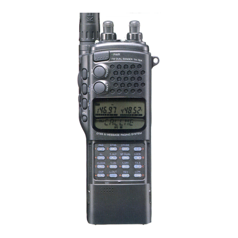
  9. Kenwood TH-75A User manual

Kenwood TH-75A User manual

Other manuals for TH-75A

3

This manual suits for next models

1

Other Kenwood Transceiver manuals

Kenwood UBZ-LH68 User manual

Kenwood

Kenwood UBZ-LH68 User manual

Kenwood TK-3230DX User manual

Kenwood

Kenwood TK-3230DX User manual

Kenwood TM-241A User manual

Kenwood

Kenwood TM-241A User manual

Kenwood Trio TS-520 User manual

Kenwood

Kenwood Trio TS-520 User manual

Kenwood TM-631A User manual

Kenwood

Kenwood TM-631A User manual

Kenwood NEXEDGE NX-720 User manual

Kenwood

Kenwood NEXEDGE NX-720 User manual

Kenwood TH-21A User manual

Kenwood

Kenwood TH-21A User manual

Kenwood TM-621A User manual

Kenwood

Kenwood TM-621A User manual

Kenwood TK-7160 User manual

Kenwood

Kenwood TK-7160 User manual

Kenwood FleetSync TK-890 User manual

Kenwood

Kenwood FleetSync TK-890 User manual

Kenwood TK-2302 User manual

Kenwood

Kenwood TK-2302 User manual

Kenwood TS-820 User manual

Kenwood

Kenwood TS-820 User manual

Kenwood TS-890S Operating manual

Kenwood

Kenwood TS-890S Operating manual

Kenwood TK-3118 User manual

Kenwood

Kenwood TK-3118 User manual

Kenwood TH-225A User manual

Kenwood

Kenwood TH-225A User manual

Kenwood TS-890S User manual

Kenwood

Kenwood TS-890S User manual

Kenwood TR-2600 A User manual

Kenwood

Kenwood TR-2600 A User manual

Kenwood TK-2360 User manual

Kenwood

Kenwood TK-2360 User manual

Kenwood TK 3200U2P - Protalk UHF - Radio User manual

Kenwood

Kenwood TK 3200U2P - Protalk UHF - Radio User manual

Kenwood TM-G707 User manual

Kenwood

Kenwood TM-G707 User manual

Kenwood NX-200GK User manual

Kenwood

Kenwood NX-200GK User manual

Kenwood NX-1000 Series User manual

Kenwood

Kenwood NX-1000 Series User manual

Kenwood TK-705D User manual

Kenwood

Kenwood TK-705D User manual

Kenwood TK-2302 User manual

Kenwood

Kenwood TK-2302 User manual

Popular Transceiver manuals by other brands

City Theatrical SHoW DMX SHoW Baby user manual

City Theatrical

City Theatrical SHoW DMX SHoW Baby user manual

Standart Horizont HX407 owner's manual

Standart Horizont

Standart Horizont HX407 owner's manual

B&G V90S quick start guide

B&G

B&G V90S quick start guide

VictelGlobal ALK300 series Operation manual

VictelGlobal

VictelGlobal ALK300 series Operation manual

Cactus Wireless Flash Transceiver V6 user manual

Cactus

Cactus Wireless Flash Transceiver V6 user manual

Yaesu FT-11R user guide

Yaesu

Yaesu FT-11R user guide

Skanti TRP 5000 instruction manual

Skanti

Skanti TRP 5000 instruction manual

ELECRAFT KX3 Installation and operation guide

ELECRAFT

ELECRAFT KX3 Installation and operation guide

American Lighting DMX512 quick start guide

American Lighting

American Lighting DMX512 quick start guide

Furuno FM-77 Operator's handbook

Furuno

Furuno FM-77 Operator's handbook

Yaesu FT-7B manual

Yaesu

Yaesu FT-7B manual

Mizuho MX-2 Operating & assembly instruction

Mizuho

Mizuho MX-2 Operating & assembly instruction

Blitz MJ-398U instruction manual

Blitz

Blitz MJ-398U instruction manual

Utilicom LongRanger 2050 Operator's manual

Utilicom

Utilicom LongRanger 2050 Operator's manual

Standart HX290UKA Service manual

Standart

Standart HX290UKA Service manual

Altronix Pace1PTM installation guide

Altronix

Altronix Pace1PTM installation guide

Kirisun PT2208 instruction manual

Kirisun

Kirisun PT2208 instruction manual

ELECRAFT KX2 manual

ELECRAFT

ELECRAFT KX2 manual

manuals.online logo
manuals.online logoBrands
  • About & Mission
  • Contact us
  • Privacy Policy
  • Terms and Conditions

Copyright 2025 Manuals.Online. All Rights Reserved.

GOOMNS>)I
144/440MHz
FM
DUAL
BANDER
TH-/75A
144/430MHz
FM
DUAL
BANDER
TH-75A
144/430MHz
FM
DUAL
BANDER
TH-75E
INSTRUCTION
MANUAL
KENWOOD
CORPORATION
@©PRINTED
IN
JAPAN
B50-8275-00(K,
M,
X,
W,
T,
P)(T)
90/12
1110987654321
89/12111098765
CONTENTS
1.
BEFORE
OPERATION
2.
SPECIFICATIONS
and
ACCESSORIES
..
3.
BATTERY
PACK
4.
OPERATION
OPERATING
CONTROLS
...
RECEIVER
OPERATION
Reception,
Frequency
selection,
Frequency
step
selection,
Programable
VFO,
A.B.C.
TRANSMITTER
OPERATION
.
F015:
MEMORY
216
-oO
PWNH
Microprocessor
initialization,
Memory
channel,
Memory
contents,
Memory
entry,
Memory
recall,
Memory
shift
SCAN
Scan
operations,
Hold/resu
g!
Band
scan,
Programmable
band
scan,
Memory
channel
scan,
Double
memory
scan,
Memory
channel
lockout,
Priority
alert
REPEATER
OPERATION..
Transmitter
offset,
Reve
Tone
and
CTCSS
operation,
ea
TONE
ALERT
SYSTEM.
BATTERY
SAVER.........
AUTOMATIC
POWER
OFF.
FAST
SQUELCH
5.
BLOCK
DIAGRAM
and
SCHEMATIC
DIAGRAM
.............
another
sheet
6.
MAINTENANCE
......o.....
ee
eeeeceeceseeeseeeteeeseeenaee
29
In
Case
of
Difficulty
7.
OPTIONAL
ACCESSORIES....................::::cccee
31
CTCSS
unit
TSU-6
1.
BEFORE
OPERATION
Thank
you
for
purchasing
this
new
transceiver.
IMPORTANT:
Please
read
this
instruction
manual
carefully
before
placing
your
transceiver
in
service.
CAUTION:
Long
transmittion
or
extended
operation
in
the
HI
power
mode
might
cause
the
rear
of
this
transceiver
to
get
warm.
Do
not
place
the
transceiver
where
the
heat
sink
(rear
panel)
might
come
in
contact
with
plastic
or
vinyl
surfaces.
Use
of
an
external
antenna
for
fixed
station
is
recommended.
SAVE
THIS
INSTRUCTION
MANUAL.
This
Instruction
Manual
covers
the
following
models.
TH-75A
:
144/440
MHz
FM
DUAL
BANDER
with
CTCSS
unit.
(U.S.A.
and
Canadian
version)
TH-75A
:
144/430
MHz
FM
DUAL
BANDER.
(Other
market)
TH-75E
:
144/430
MHz
FM
DUAL
BANDER.
(U.K.
and
European
version)
The
following
explicit
definitions
apply
in
this
manual:
NOTE
:
If
disregarded,
inconvenience
only,
no
risk
of
equipment
damage
or
personal
injury.
CAUTION:
Equipment
damage
may
occur,
but
not
per-
sonal
injury.
2.
SPECIFICATIONS
2-1.
SPECIFICATIONS
and
ACCESSORIES
2m
Band
70
cm
Band
TH-76A
U.S.A.
version
144
to
148
438
to
450
Bae
eeR
TH-75E
European
and
U.K.
version
144
to
146
430
to
440
TH-75A
Others
144
to
148
430
to
440
MODE
F3E
(FM)
MEMORY
CHANNELS
10+1
I
10+1
FREQUENCY
STEP
(kHz)
5,
10,
18,
20,
12.5,
26
ANTENNA
IMPEDANCE
(0)
50
POWER
REQUIREMENT
6.3~
16
(7.2
VDC
nominal)
13.8V
Approx.
1.4
A
Approx.
1.5
A
i
hg
HI
|
9
V
(with
BT-6)
Approx.
1.2
A
Approx.
1.3
A
S|
cup.
|
mode
7.2
V
(with
PB-5/6/7/9)
‘Approx.
1A
Approx.
1.1A
Ser
LO
transmit
mode
Approx.
0.6
A
Approx.
0.6
A
&
DRAIN
|
Single
|
RECEIVE
mode
with
no
signal_|
Approx.
45
mA
Approx.
50
mA
band
|
BATTERY
SAVER
mode
Approx.
12
mA
Approx.
13
mA
Dual
|
RECEIVE
mode
with
no
signal
Approx.
83
mA
band
|
BATTERY
SAVER
mode
‘Approx.
20
mA
AUTOMATIC
POWER
OFF
mode
Approx.
3
mA
GROUND
Negative
DIMENSIONS
_ |
Projections
not
included
(mm)
58x
179
29.5
(2.3x
7X
1.2
inch)
(WxHxD)
Projections
included
(mm)
74x
193
x40
(2.9x7.6x
1.6
inch)
WEIGHT
(g)___
With
NiCd
Battery
and
Antenna
|
510
(1.1
Ibs.)
OPERATING
TEMPERATURE
=20°C~
+50°C
(—4°F~122°F)
MICROPHONE
IMPEDANCE
2ko
m
13.8V
More
than
5
W
B]
oureur
Hi
[9
V
(with
BT-6)
‘Approx.
3
W
Approx.
2.5
W
|
POWER
7.2
V
(with
PB-5/6/7/9)
Approx.
1.5
W.
Approx.
1.5
W.
FA
to
‘Approx.
0.5
W
<
MODULATION
REACTANCE
f
|
MAXIMUM
FREQUENCY
DEVIATION
(kHz)
+5
SPURIOUS
RADIATION
HI/LO
Less than
—
60
dB/—
50
dB
CIRCUITRY
[DOUBLE
CONVERSION
SUPERHETERODYNE
INTERMEDIATE
|
1st
IF
(MHz)
16.9
59.525
|
FREQUENCY
_[
2nd
IF
(kHz)
455
5
|
SENSITIVITY
12
dB
SINAD
|
Less than
0.16,V
|
Less than
0.18:V
|
SQUELCH
SENSITIVITY
Less than
0.1
.V
@
-6
dB
More
than
12
kHz
SELECTIVITY:
»
anna
Less
than
28
kHz
AUDIO
OUTPUT
POWER
(across
8
@
load
10%
distortion)
More
than
400
mW/at
9
V
NOTES:
1.
Circuit
and
ratings
are
subject
to
change
without
notice
due
to
advancement
in
technology.
2.
Recommended
duty
cycle:
1
minute
Transmis-
sion,
3
minutes
Reception
2-2.
ACCESSORIES
Unpack
your
new
transceiver
carefully,
and
exa-
mine
it
for
visible
damage.
If
the
equipment
has
been
damaged
in
shipment,
notify
the
transporta-
tion
company
immediately.
Save
the
boxes
and
packing
material
for
future
shipping.
The
following
accessories
should
have been
includ-
ed
in
the
box
with
the
transceiver.
Antenna....
T90-0388-05...1
ea.
Belt
Hook
J29-0424-04...1
ea.
Hand
strap.
J69-0312-04...1
ea.
W09-0507-05..1
ea.
NiCd
Battery
pack
(PB-6).
Battery
charger
for
U.S.A.
version
(120V)
adesincavesaseuck
W09-0382-15
for
European
version
(220V)
inidessauaaee
see
WO09-0388-05
for
U.K.
version
(240V)....WO9-0387-05
for
Oceania
version
(240V)
WO09-0386-05
WO09-0385-05
for
other
market
(120V).
Instruction
Manual
..
Warranty
Card....
(U.S.A.,
Canada,
and
European
version)
B50-8275-XX
.1
copy
1
ea.
3.
BATTERY
PACK
3-1.
NiCd
BATTERY
PACK
(PB-6)
This
battery
pack
has
not
been
charged
at
the
factory
in
order
to
provide
you
with
the
greatest
number
of
charge/dis-
charge
cycles.
You
must
charge
the
battery
before
use.
The
battery
pack
will
require
several
charge/discharge
cycles
be-
fore
you
can
expect
to
see
the
maximum
operating
period
between
charges.
If
the
battery
will
be
stored
for
greater
than
2
months
it
should
be
recharged
before
use.
3-2.
RECHARGING
Msxe”
1.
Slide
the
adapter
onto
the
NiCd
battery
pack.
2.
Plug
the
supplied
charger
into
an
AC
outlet.
3.
Do
not
allow
the
battery
to
charge
for
greater
than
15
hours.
The
useful
life
and
battery
performance
will
be
reduced
if
you
exceed
the
recommended
charge
period.
NOTE:
Recharging
should
be
per-
formed
within
an
ambient
temperature
range
of
between
5°C~40°C
(41°F
~
104°F).
Recharging
the
battery
out-
side
of
this
range
may
not
al-
low
the
battery
to
reach
full
charge.
to
AC
outlet
3-3.
MANGANESE
or
ALKALINE
BAT-
TERIES
(Optional
Battery
Case
BT-6)
Install
6
x
R6
(AA)
manganese
or
alkaline
batteries
in
the
bat-
Press
down
on
the
hook
in
the
tery
holder.
Pay
close
atten-
‘Middle
of
the
battery
case
top
*
ty
to
open.
tion
the
battery
polarities
marked
in
the
holder.
We
Hook
recommend
the
use
of
high
|
performance
manganese
bat-
teries
for
the
greatest
operat-
ing
time.
NOTE:
——________
Do
not
install
NiCd
batteries
and
attempt
to
charge
them
with
the
supplied
charger.
There
is
no
battery
protection
circuit
in
the
battery
holder.
3-4.
INSTALLING
THE
BATTERY
PACK
Align
the
grooves
in
the
bat-
Release
button
tery
pack
with
the
transceiver
>
and
slide
the
pack
to
the
right
until
it
locks
in
place.
To
remove
the
battery
pack
push
up
on
the
release
button
and
slide
the
pack
to
the
left.
3-5.
BATTERY
VOLTAGE
LEVEL
METER
The
S
meter
indicates
the
rela-
tive
battery
voltage
during
Manganese
or
Alkaline
transmit.
a
b
Recharge
or
replace
the
bat-
mitexies
teries
when
the
level
reaches
New
myeeg
te
batteries
replace
the
low
indicator.
7
|
Approximate
battery
condition
NiCd
Battery
pack
model
mAh
Vv
Fully
charged
Fully
discharged
ageret
"ag
Ae
PB-6
600
peg
|
600
|
72
”
PB-7
1100
Zz
=f
F
pp-8
|
600
|
12
=A
z
3-6.
OPERATING
TIME
TH-75
series
Transmitting.
Receiving
..
ti
AF
OUTPUT...
Nica
*
Battery
voltage
is
mea:
600
transmission
(Hi).
battery
1
2v
12
mAh
(PB-8)
10
|
NiCd
battery
7.2V
200
mAh
(PB-5)
NiCd
battery
7.2
V
600
mAh
(PB-6)
NiCd
battery
7.2
V
1100
mAh
(PB-7)
Lower
limit
voltage
range
for
transmission
6
4
|
Mengansese
—
Manganese
battery
‘AA
Alkaline
manganese
battery
(BT-6)
_(Low-Power)(BT-6)
battery
(BT-6)
2
°
ens
60
120
180
240
300
(minutes)
We
recommend
use
of
the
NiCd
battery
pack
for
long
trans-
mission
or
extended
operation.
Manganese
battery
(except
Alkaline
manganese
battery)
is
suitable
only
for
LOW
power
transmission.
4.
OPERATION
4-1.
OPERATING
CONTROLS
©
Antenna
connector
Connect
the
antenna
that
is
supplied
to
this
jack.
Twist
to
lock.
@
HI-LO
switch
This
switch
is
used
to
select
the
transmit
output
power.
@
MIC
jack
This
jack
is
used
for
connection
of
an
external
micro-
phone.
The
use
of
an
electret
type
microphone
is
recom-
mended.
Input
impedance
is
2
kQ
and
the
DC
voltage
on
this
ter-
minal
is
approximately
4
V
(max.
3.5
mA).
NOTE:
The
use
of
a
dynamic
microphone
is
not
recommended.
Speaker
sP
Ground
th
5V
MIC
MIC
PTT
PET:
@
Speaker
jack
This
jack
is
used
to
connect
an
external
speaker
or
ear-
phone.
The
recommended
impedance
is
8
Q.
©
VHF
SOL
control
This
control
is
used
to
select
the
desired
SOL
threshold
level
of
the
VHF
frequency
band.
©
VOL
control/Power
switch
The
volume
control
and
power
switch
are
combined.
Rotating
the
control
clockwise
will
turn
ON
the
tran-
sceiver.
Advancing
the
control
further
clockwise
will
in-
crease
the
volume
of
both
bands.
The
BAL
control
proportions
the
volume
among
the
two
bands.
@
UHF SOL
control
This
control
is
used
to
select
the
desired
SQL
threshold
level
of
the
UHF
frequency
band.
BALANCE
control
This
control
proportions
the
total
audio
volume
among
the
two
bands.
MAIN
position
Audio
only
from
the
MAIN
band
Center
position
Equal
audio
from
both
bands
SUB
position
Audio
only
from
the
SUB
band
©
Tuning
control
This
control
is
used
to
select
the
desired
transmit-
ter/receiver
frequency,
memory
channel,
frequency
step,
tone
frequency,
and
scan
direction.
@
F
key
This
key
is
used
to
activate
control
of
the
functions
print-
ed
above
the
various
front
panel
controls.
The
‘’F’’
indi-
cator
will
turn
ON
for
approximately
10
seconds.
You
must
press
the
desired
2nd
function
key
before
the
indi-
cator turns
off.
@
TONE/T.SEL
key
This
key
is
used
to
activate
the
subaudible
tone
encorder.
Pressing
the
key
within
10
seconds
of
pressing
the
F
key
will
switch
to
the
tone
frequency
selection
mode.
The
Tuning
control
can
then
be
used
to
select
the
desired
tone
frequency.
@
SHIFT/REV
key
This
key
is
used
to
select
the
desired
transmitter
offset
direction.
Pressing
the
key
will
cause
the
radio
to
shift
from
one
offset
direction
to
the
other,
i.e.
+
to
—
to
sim-
plex
where
no
indicator
showes.
[—
to
—
—
for
Europe-
an
version
(UHF
band)].
Pressing
the
key
within
10
seconds
of
pressing
the
F
key
will
reverse
the
transmit/receive
frequencise
during
repeater
operations.
If
you
have
selected
simplex
this
key
will
not
function.
@
UP/DWN
(Sub
tuning)
keys
These
keys
are
used
to
select
the
desired
SUB
band
receive
frequency
or
Memory
channel.
Pressing
the
UP
key
within
10
seconds
of
pressing
the
M
key
will
enter
the
upper
limit
for
the
programmable
VFO
tuning
limit
function.
Pressing
the
DWN
key
within
10
seconds
of
pressing
the
M
key
will
enter
the
lower
limit
for
the
programmable
VFO
tuning
limit
function.
©
M/TX.S
key
This
key
and
numeric
key
are
used
to
store
the
displayed
data
into
memory.
Pressing
the
key
within
10
seconds
of
pressing
the
F
key
will
turn
the
TX.STOP
function
ON
and
OFF.
ENT/K.LOCK
key
In
the
VFO
mode
this
key
is
used
to
switch
to
the
direct
keyboard
frequency
entry
mode.
In
the
MR
or
CALL
channel
mode
this
key
is
used
to
trans-
fer
the
contents
of
the
channel
to
the
VFO
mode
(Memory
shift).
Pressing
the
key
within
10
seconds
of
pressing
the
F
key
will
deactivate
all
functions
except
the
PTT,
MONI,
LAMP,
F
then
LOCK
keys.
@
SCAN/DMS
key
This
key
is
used
to start
or
stop
scanning.
Pressing
the
key
within
10
seconds
of
pressing
the
F
key
will
start
or
stop
Double
Memory
Scanning.
CALL
key
This
key
is
used
to
activate
the
Call
channel
function.
@
MICROPHONE
@
BAND/A.B.C.
(Automatic
Band
Change)
key
This
key
is
used
to
exchange
the
contents
of
the
MAIN
and
SUB
band.
When
this
key
is
pressed
within
10
seconds
of
pressing
the
F
key,
the
contents
of
the
SUB
band
will
be
trans-
fered
to
the
MAIN
band
whenever
a
signal
is
received
at
the
SUB
band,
which
is
strong
enough
to
open
the
squelch.
The
contents
of
the
MAIN
band
are
transfered
to
the
SUB
band
at
the
same
time.
@
MHz/STEP
key
This
key
is
used
to
tell
the
microprocessor
that
you
wish
to
increase
or
decrease
the
operating
frequency
in
1
MHz
increments.
During
VFO
operation
pressing
the
key
within
10
seconds
of
pressing
the
F
key
will
switch
to
the
frequency
step
selection
mode.
@
DUAL/DUP
key
This
key
is
used
to
turn
the
SUB
band
ON
or
OFF.
Pressing
the
key
within
10
seconds
of
pressing
the
F
key
will
cause
the
duplex
function
to
activate.
@
1/AL
key
This
key
is
used
to
turn
memory
channel
1
ON
or
OFF.
Pressing
the
key
within
10
seconds
of
pressing
the
ENT
key
will
enter
number
1.
Pressing
the
key
within
10
seconds
of
pressing
the
F
key
will
check
Memory
Channel
1
at
approx.
5
second
inter-
vals.
If
the
channel
is
busy,
a
beep
will
sound.
©
2/T.ALT
key
This
key
is
used
to
turn
memory
channel
2
ON
or
OFF.
Pressing
the
key
within
10
seconds
of
pressing
the
ENT
key
will
enter
number
2.
Pressing
the
key
within
10
seconds
of
pressing
the
F
key
will
turn
the
Tone
Alert
function
ON
or
OFF.
3/CTCSS
key
This
key
is
used
to
turn
memory
channel
3
ON
or
OFF.
Pressing
the
key
within
10
seconds
of
pressing
the
ENT
key
will
enter
number
3.
Pressing
the
key
within
10
seconds
of
pressing
the
F
key
will
turn
the
CTCSS
function
ON
or
OFF.
@
4/TO/CO
keys
This
key
is
used
to
turn
memory
channel
4
ON
or
OFF.
Pressing
the
key
within
10
seconds
of
pressing
the
ENT
key
will
enter
number
4.
Pressing
the
key
within
10
seconds
of
pressing
the
F
key
will
toggle
the
hold/resume
mode
alternately
from
Time
Operated
scan
to
Carrier
Operated
scan.
5/BEEP
key
This
key
is
used
to
turn
memory
channel
5
ON
or
OFF.
Pressing
the
key
within
10
seconds
of
pressing
the
ENT
key
will
enter
number
5.
Pressing
the
key
within
10
seconds
of
pressing
the
F
key
will
turn
the
audio
confirmation
beep
ON
or
OFF.
©
6/CT
V/U
key
This
key
is
used
to
turn
memory
channel
6
ON
or
OFF.
Pressing
the
key
within
10
seconds
of
pressing
the
ENT
key
will
enter
number
6.
Pressing
the
key
within
10
seconds
of
pressing
the
F
key
will
switch
the
CTCSS
function
alternately
between
the
VHF
band
and
UHF
band.
TISAVE
key
This
key
is
used
to
turn
memory
channel
7
ON
or
OFF.
Pressing
the
key
within
10
seconds
of
pressing
the
ENT
key
will
enter
number
7.
Pressing
the
key
within
10
seconds
of
pressing
the
F
key
will
turn
the
Battery
Saver
function
ON
or
OFF.
@
8/APO
key
This
key
is
used
to
turn
memory
channel
8
ON
or
OFF.
Pressing
the
key
within
10
seconds
of
pressing
the
ENT
key
will
enter
number
8.
Pressing
the
key
within
10
seconds
of
pressing
the
F
key
will
turn
the
Automatic
Power
OFF
function
ON
or
OFF.
@
9/LOCK
key
This
key
is
used
to
turn
memory
channel
9
ON
or
OFF.
Pressing
the
key
within
10
seconds
of
pressing
the
ENT
key
will
enter
number
9.
Pressing
the
key
within
10
seconds
of
pressing
the
F
key
will
deactivate
the
Tuning
control
and
all
functions
ex-
cept
the
PTT,
MONI,
LAMP,
and
F
then
K.LOCK
keys.
@
O/L.OUT
key
This
key
is
used
to
turn
memory
channel
O
ON
or
OFF.
Pressing
the
key
within
10
seconds
of
pressing
the
ENT
key
will
enter
number
0.
Pressing
the
key
within
10
seconds
of
pressing
the
F
key
will
turn
the
memory
channel
lock
out
function
ON
or
OFF.
MONITOR
switch
When
operating
in
the
CTCSS
mode
you
can use
this
key
to
determine
if
the
fre-
quency
is
in
use
before
transmitting.
Pressing
the
key
will
disable
the
CTCSS
function
as
long
as
the
key
is
held
®
depressed.
@
Lamp
switch
This
switch
is
used
to
control
the
night
lamp
on
the
display.
The
lamp
will
turn
it-
self
off
automatically
5
seconds
after
the
last
key
operation.
PTT
switch
Press
this
switch
whenever
you
wish
to
transmit.
@
Release
button
Press
this
button
up
to
release
the
battery
pack.
DC
IN
terminal
This
terminal
is
used
for
an
external
pow-
er
supply.
Input
voltage
is
13.8
VDC
nominal.
The
center
is
the
+
side
and
the
sleeve
is
—
side.
CAUTION:
You
should
turn
the
power
switch
OFF
when
connecting
this
terminal.
Pay
close
attention
to
the
polarity.
As
a
precaution,
do
not
remove
the
bat-
tery
pack
when
an
external
power
supply
is
used.
Use
the
KENWOOD
PG-2V
or
PG-3E
op-
tional
cable
for
the
connection.
ee
R
iis
STOP
"9
AIR
LOCK
=cm
aa
298
B99
92
‘ORRSER
®
@
cota
Lee
“EEE
[E>
SAVE
APO
©
©
Ob860
©
@g
Displays
the
selected
transmitter
offset
-+
direction.
@R
ON
when
the
Reverse
function
is
active.
@TX.STOP
ON
when
the
TX.STOP
function
is
active.
@K.LOCK
—_
ON
when
the
K.LOCK
function
is
active.
LOCK
ON
when
the
LOCK
function
is
active.
©
RE
ON
during
transmit.
ON
when
the
Tone
Alert
System
is
active.
The
indicator
will
flash
when
a
signal
is
received.
This
level
meter
indicates
the
relative
receive
input
strength
or
battery
voltage
level
during
transmit.”
c
ON
when
the
SUB
band
frequency
dis-
plays
CALL
channel.
@
M
ON
when
the
SUB
band
frequency
dis-
plays
a
memory
channel.
CTCSS
ON
when
the
CTCSS
function
is
active.
O
Ve
-U
Displays
the
selected
CTCSS
band.
®
Displays
the
operating
frequency
to
the
886.888.
nearest
kHz,
the
frequency
step
size,
or
the
tone
frequency
of
the
MAIN
band.
ON
when
the
Fast
Squelch
function
is
active.
Flashes
when
Scanning.
®
ON
when
the
Tone
function
is
active.
(©)
ON
when
the
Priority
Alert
system
is
active.
®
Co
ON
when
Carrier
Operated
scan
is
selected.
ON
during
duplex
operations.
(0)
ON
when
the
A.B.C.
(Automatic
Band
Change)
function
is
active.
M
ON
when
the
MAIN
band
frequency
dis-
plays
a
memory
channel.