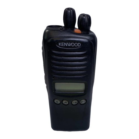
TK-3000
4
Note:
• The data stored in the personal computer must match
Model Name and Model Type when it is written into EE-
PROM.
• Do not press the [PTT] key during data transmission or
reception.
3-3. KPG-22A Description
(PC programming interface cable: Option)
The KPG-22A is required to interface the transceiver with
the computer. It has a circuit in its D-sub connector (KPG-22A:
9-pin) case that converts the RS-232C logic level to the TTL
level.
The KPG-22A connects the SP/MIC connector of the
transceiver to the RS-232C serial port of the computer.
3-4. KPG-22U Description
(USB programming interface cable: Option)
The KPG-22U is a cable which connects to a USB port
on a computer.
When using the KPG-22U, install the supplied CD-ROM
(with driver software) in the computer. The KPG-22U driver
runs under Windows XP, Vista, 7 or 8.
3-5. Programming Software KPG-137D Description
The KPG-137D is the programming software for the
transceiver supplied on a CD-ROM. This software runs un-
der windows XP, Vista, 7 or 8 on a PC. The software on this
disk allows a user to program the transceiver via Program-
ming interface cable (KPG-22A/22U).
Note:
• Use the FPU that matches the market when you first set
the market code and model name/frequency data to the
service unit. The unit set by mistake cannot be restored.
• Receive frequencies listed below may result in the in-
terference of reception due to the harmonics of internal
oscillators. Enter a frequency not listed in the table.
No.
FREQUENCY (MHz)
TK-3000
K,M,M3,M7
TK-3000
M2,M4 TK-3000 M6 TK-3000
E,T2 *1
1 441.59375 403.19375 364.79375 441.59375
2 441.59500 403.19500 364.79500 441.59500
3 441.60000 403.20000 364.80000 441.60000
4 441.60500 403.20500 364.80500 441.60500
5 441.60625 403.20625 364.80625 441.60625
6 460.79375 422.39375 383.99375 460.79375
7 460.79500 422.39500 383.99500 460.79500
8 460.80000 422.40000 384.00000 460.80000
9 460.80500 422.40500 384.00500 460.80500
10 460.80625 422.40625 384.00625 460.80625
11 479.99375 - - 479.99375
12 479.99500 - - 479.99500
13 480.00000 - - 480.00000
*1: Guaranteed frequency range 440~470MHz
REALIGNMENT
1. Modes
Mode Function
User mode For normal use.
PC mode Used for communication between the trans-
ceiver and PC.
Data programming
mode
Used to read and write frequency data and
other features to and from the transceiver.
PC test mode Used to check the transceiver using the PC.
This feature is included in the FPU.
Clone mode Used to transfer programming data from
one transceiver to another.
2. How to Enter Each Mode
Mode Operation
User mode Power ON
PC mode Received commands from PC
Clone mode [PTT]+[Side]+Power ON (Two seconds)
3. PC Mode
3-1. Preface
The transceiver is programmed by using a personal com-
puter, a programming interface (KPG-22A/22U) and FPU-
programming software (KPG-137D: ver. 2.20 or later).
The programming software can be used with a PC. Fig-
ure 1 shows the setup of a PC for programming.
3-2. Connection Procedure
1. Connect the transceiver to the personal computer with
the interface cable.
Note:
• You must install the KPG-22 driver in the computer to use
the USB programming interface cable (KPG-22U).
2. When the POWER is switched on, user mode can be
entered immediately. When the PC sends a command,
the transceiver enters PC mode.
When data is read from the transceiver, the red LED
lights.
When data is written to by the transceiver, the green LED
lights.
User mode
Data programming mode
PC test mode PC tuning mode
PC mode
Clone mode
