AI\
~
,~
-~
~
.f
I
,....
~
~
15-670
CIRCUITDESCRIPTION
OUTLINE
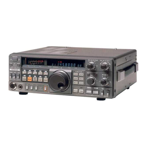
The TS-670 is asingle conversion 4-band transceiver having
an intermediate frequency of 8.83 MHz. In the FM reception
mode double conversion at 455 KHz is employed.
The Phase Locked Loop (PLl) uses adigital variable frequen-
cy oscillator (VFO) control system at a 10 and 100 Hz step
switching rate in all modes but FM, in which 10KHz and
100 KHz switching is automatically selected by the
transceivers microprocessor. Excluding only the FM receiver
second conversion oscillator, all oscillator frequencies
generated in this device are including the carrier injection fre-
quencies controlled by and synthesized from asingle
reference frequency source of 24 MHz.
The main auxiliary functions include two VFOs, 80-channel
memory, frequency specify function, memory scan, program
scan, IF shift, RIT, NB, power control and other useful func-
tions.
RECEPTION CIRCUIT CONFIGURATION
The TS-670 reception system uses asingle conversion at IF
8.83 MHz in SSB, CW and AM modes. In the FM mode, dou-
ble conversion is used with asecond IF at 455 kHz.
The RF stage is divided into 50 MHz, 7 MHz, 21 MHz and
28 MHz, while the stage following the mixer is common.
The signal received by the antenna is fed through the Low
Pass Filter (LPF) (common for both transmission and recep-
tion), which is relay switched according to band, and antenna
relay RL1 on the Filter unit before being input to the RF unit
PA terminal.
The signal is fed through broad-band transformer Tl , RF atte-
nuating relay RL2, 8.83 MHz trap T2 and T3, IF traps L2 to
L4, and for 50 MHz Band, the signal is stepped up by anten-
na coil T4 and T5. It is then amplified by RF amp 01 (2SK74
(l)) and fed through Band PassFilter (BPF)T6 to T8 before
being output from buffer amp 02. HF signals are stepped up
by broadband transformer T9, and then fed through either a
7, 21, or 28 MHz BPF 7 MHz; T12, T15 and T18.
21 MHz; T11, T14 and T17. 28 MHz; TlO, T13 and T16.
It is then amplified by RFamp 03 (3SK74 (l)) before being
output from buffer amp 04.
Both 50 MHz and HF signals are converted abalanced signal
by broad-band transformer T20, then mixed with the local
oscillator by common mixers 05 and 06 (3SK122(l) x 2) to
become an 8.83 MHz intermediate frequency signal T19 is
an 8.83 MHz trap.
This signal is fed through ceramic filter CFl , then amplified by
the first IF amp 07 (3SK73 GR), and fed through Noise
Blanker (NB) gate diode 017 through 020 before being out-
put to the IF unit via the RIF terminal in the SSB, CW and AM
modes. In the FM mode, the signal is first fed through buffer
amp 08, and is then output to the FM unit through the FMI
terminal. The noise blanker samples from the output of
ceramic filter CF1, feeds this through buffer amp 011
(2SK192 (Y)), then amplifies this by 012,013 and 014 the
noise component is detected by diodes 023 and 024 before
driving switching transistor 015 to switch the NB gate.
The NB gate also serves as a blanking circuit to eliminate
Phase Locked Loop (PLl) "click" noise when the Voltage
Controled Oscillator (VCO) resets (09 and 010).
The signal from the RF unit RIFterminal is fed to the IFunit RIF
terminal through matching transformer L1 and through
mode-selected Monolithic Crystal Filters (MCFs), and is then
amplified by IF amps 01 and 04 (3SK73).
The signal in SSB and CW modes is detected by product
detector 026 through 029 (1N60), amplified by audio pre-
amp 07 which is common to each mode, and fed through
squelch switching transistor 08 before being output to the
gain control.
In the FM mode, the signal is detected by diode 025, then
passed through buffer amp 06 before being fed to pre-amp
07.
In FM mode, the signal is mixed, amplified and detected in the
FM unit, then fed through the IF unit FAF terminal before be-
ing input to pre-amp 07.
The audio input to this pre-amplifier is switched by either
030, for the SSB and CW modes, 032 for the AM mode or
031 for the FM mode.
TRANSMISSION CIRCUIT CONFIGURATION
Like the reception system, the transmission system uses
single conversion in the SSB, CW and AM modes, and uses
double conversion in the FM mode.
In the SSB, CW and AM modes, audio from the MIC input ter-
minal is amplified by 034 on the IF unit, then fed through the
mic gain control, and further amplified by 035 before being
input to balanced modulator 036 (AN612).
In the SSB mode, the output from this modulator is Oouble
Side Band, and after passing through the Monolithic Crystal
Filter (MCF) YK-88S3 becomes an SSB signal.
In the AM and CW modes, modulator balance is lost by apply-
ing the OC voltage to pin 1 of this modulator. At this time, the
amount of carrier to be injected is determined by varying the
OC bias current to pin diode 044 (MI204). In the AM mode,
the output from 036 is fed through R5 (680 ohm).
(However, when AM filter YK-88A is mounted, the signal is
also fed through this filter.) In the CW mode, the output is fed
through SSB filter YK-88S3. Each mode signal fed through
the filter is amplified by transmitter IF amp 024, then output
to the RF unit.
In the FM mode, the audio signal fed through mic amp 034
which is commonly used is fed to the FM unit where the signal
is .FM-modulated using the 8831.5 kHz carrier frequency,
the out-put of which is input to NO.1 transmitter balanced
mixers 024 and 025 (3SK122 x 2) of the RF unit.
The switching between the SSB, CW, AM signals and the FM
signal is performed by switching diodes 032 and 038.
The ALC (Automatic Level Control) is performed on transmit-
ter IF amp 042 of the IF unit.
The transmitter signal from the IF unit is mixed with band-
wise VCO output at first transmitter balanced mixers 024 and
3
