manuals.online logo
Brands
  1. Home
  2. •
  3. Brands
  4. •
  5. Kenwood
  6. •
  7. Transceiver
  8. •
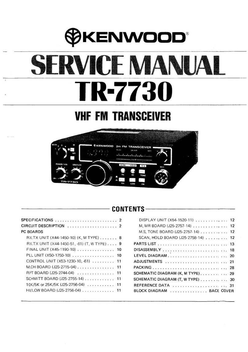
  9. Kenwood TR-7730 User manual

Kenwood TR-7730 User manual

2m
FM
TRANSCEIVER
INTRODUCTION
‘You
are
the
owner
of
our
latest
product,
the
new
TR-7730
transceiver.
Pi
1g
Your
transceiver
in
service.
The
unit
has
been
carefully
engineered
and
manufactured
carefully
before
pla
fe
read
this
instruction
manual
to
rigid
quality
standards,
and
should
give
you
satisfactory
and
dependable
operation
for
many
years.
AFTER
UNPACKING
‘©
Shipping
container:
Save
the
boxes
and
packing
in
the
event
your
unit
needs
to
be
transported
for
remote
operation,
maintenance,
or
service.
©
The
following
explicit
definitions
apply
in
this
manual:
ACCESSORIES
svsseeee
3
Caretully
unpack
your
TR-7730
and
check
that
it
is
sup-
plied
with
the
following
accessories:
Note:
If
disregarded,
inconvenience
only,
no
risk
of
equipment
damage
or
personal
injury:
Caution:
Equipment
damage
may
occur,
but
not
personal
injury.
CONTENTS
FEATURES
......
BEFORE
U!
3
SPECIFICATIONS
..
SECTION
1,
PREPARATION
FOR
USE
1.1
Installation.
SECTION
2,
CONTROLS
AND
TERMINALS.
2.1
Front
panel
2.2
Rear
panel
.
SECTION
3,
OPERATION
..
3.1
Transmitter
precautions...
3.2
Frequency selection
ses
3.3
Priority
of
controls,
3.4
Memory
switch
3.5
Scan
operation.
3.6
TX
Offset
switch
..
3.7
Squelct
3.8
HI/LOW
switch,
3.9
Autopatch
operation.
3.10
TONE
switch..
3.11
Bail
and
Foot
installation.
3.12
Adjustments
.
SECTION
4.
ADDITIONAL
INFORMATION.
SECTION
5.
OPTIONAL
ACCESSORIES.
SCHEMATIC
DIAGRAMS
..
BLOCK
DIAGRAMS......
1
Dynamic
microphone
(with
U/D
switch)
(T90-0313-05).....
2
Mounting
bracket
(A13-0618-22).......
Mounting
boss
(J32-0748-04)
.
Machine
screw
(3¢
x
6)
Machine
screw
(36
12)
..
Pan
head
screw
(6¢
x
8)
Fiat
washer
(66)
Spring
washer
(69).
Flange
nut
(66)
(For
installation,
see
page
6
and
13)
3
Leg
Front
bail
(J02-0420-04)..
esssees]
piece
Bail
mounting hardware
(J21-2676-04)
...
Rear
foot
(J02-0022-05).
4
DC
power
cord
(E30-1
689-05)
5
Fuse
(6A)
(FO5-6021-05)
6
Miniature
plug
(for
external
speaker)
{€12-0001-08)...
eesseeeseeeeeT
POCO
FEATURES
een
2.
Rotary
encoder,
5
kHz
or
10
kHz-step
digital
VFO
system
specifically
designed
for
mobile
operation.
3.
High
/_
RE
amplifier
using
a
iow
noise
dual
gate
MOS
FET.
4,
PLL
circuit
for
direct
VCO
(Voltage
Controlled
Oscillator)
output
at
144
MHz
assures
excellent
spurious
characteristic.
5.
6.
BUSY
and
MEMORY
scan
functions
stop
scan
operation
when
a
signal
is
present.
Five
memory
channels.
Two
different
frequencies
(transmit
and
receive)
are
stored
in
CHS,
permitting
“‘odd-split””
repeater
operation.
7.
Hand
microphone
with
UP-DOWN
switch.
8.
TX
OFFSET
Switch
shifts
frequencies
+600
kHz
for
standard
repeater
operation.
9.
RF
POWER
HI(25
W)
—
LOW
(5
W)
select
switch.
10,
Red
LEO
frequency
display.
11,
S
and
RF
METER
LED
bar
indicator.
12,
External
BACK
UP
terminal.
13.
Extended
frequency
coverage
(143.900~
148.995
MHz)
in
switchable
5
kHz
or
10
kHz
steps,
allowing
simplex
and
repeater
operation
on
many
MARS
frequencies.
BEFORE
USE
‘These
are
factory
adjustments.
cool
this unit
BEFORE
transmitting.
Keep
equipment
away
from heat
and out
of
direct
sunlight.
SPECIFICATIONS
Semiconductors
15
Transistors
46.
FETs
7
Diodes
a1
144,000
to
147.995
MHz
Digital
control,
phase
locked
VCO
Frequency
range.
Frequency
synthesizer
Mode
Antenna
impedance
Power
requirement...
Grounding
Negative
Operating
temperature......
~20°C
to
+60°C
Current
drain
....sse
.0.4A
in
receive
mode
with
no
input
signal
5.5A
in
HI
transmit
mode
(Approx.)
3A
in
LOW
transmit
mode
(Approx.)
Less
than
2.5
mA
for
memory
back
up
(from
power
supply)
47.5
mm
(5-3/4")
wide
51.5
mm
(2°)
high
198.0
mm
(7-3/4")
deep
(projections
excluded)
1.5
kg
(3.3
Ibs)
(Approx.)
Dimensions.
Weight...
(Transmitter
Section}
RF
output
power
(at
13.8
VDC,
50
Pod)...
ssesslll
25
Watts
min.
LOW
5
Warts
approx.
(Adjustable!
-+».Variable
reactance
direct
shift
1s
than
+
20x
10
Modulation...
Frequency
tolerance...
{~10°C~
+502¢)
Spurious
radiation
-HI
Less
then
~
60
48
LOW
Less than
~53
48
5
kHz
Dynamic
microphone
with
PTT,
up,
down,
switche:
Maximum
frequency
deviation
(FM)
Microphone
5009
--.Double
conversion
superheterodyne
1st
IF
10.7
MHz
2nd
IF
455
kHz
Better
than
0.5
nV
for
30
48
S/N
Better
than
0.25
zV
for
12
dB
SINAD
.sMore
than
12
kHz
(—6
dB)
Less than
25
kHz
(—60
d8)
Better
than
60
dB
0.16
pV
(threshold)
‘More
than
2.0
watts
across
8
ohm
load
(10%
dist.)
Intermediate
frequency
..
Receiver
sensitivity
Receiver
selectivity
...
Spurious
response.
‘Squelch
sensitivity
Audio
output...
Note:
Circuit
and
ratings
are
subject
to
change
without
notice
due
to
developments
in
technology.
SECTION
1.
PREPARATION
FOR USE
1.1
INSTALLATION
1.1.1,
Interconnection
Connect
the
antenna
and
power
supply
as
shown
in
Fig.
1-1
for
fixed
station
or
mobile
operation.
1.1.2.
MOBILE
installation
©
Installation
location
Using
the
supplied
mounting
bracket,
install
the
transceiver
under
the
dashboard
or
on
the
side
of
the
console
in
your
car.
Refer
to
Fig.
1-2.
Care
should
be
taken
to
allow
free
circulation
of
air
around
the
heat
sink
of
the
rear
panel.
If
your
car
is
equipped
with
an
electronic
fuel
injector,
the
transceiver
should
be
as
far
from
the
control
equip-
‘ment
as
possible.
©
Antenna
installation
Various
types
of
antennas
for
2
meters
mobile
operation
are
available,
NOTE:
For
gutter-mount
installation,
the
antenna
bracket
must
be
grounded
to
the
car
body
as
shown
in
Fig.
1-2.
Affix
the
antenna
securely,
referring
to
the
antenna
instruc-
tion.
‘©
Power
supply
Connect
the
supplied
power
cord
with
fuse
directly
to
the
battery
terminals.
Connecting
to
the
cigarette
lighter
socket
can
cause
a
poor
connection,
and
excessive
voltage
drop.
©
Back
up
power
for
micro-processor
With
power
supplied
from
battery,
the
micro-processor
keeps
operating
even when
the
power
switch
is
OFF.
In
this
case,
current
drain
is
very
low,
approximately
2mA.
‘The
car
can
be
parked
overnight
with
little
battery
power
consumed.
However,
when
the car
is
to
be
parked
for
a
long
period
‘of
time
(more
than
1
month),
it
is
advisable
to
discon-
ect
the
power
plug.
in
this
case,
the
back
up
function
is,
disabled.
1f
power
is
diconnected,
the
back-up
fonction
is
retained
for
only
1
—
1.5
sec.
If
instantaneous
voltage
drop
at
engine-starting
continues
for
more
than
2
sec,
the
micro
processor
will
be
reset
and
the
memory
cleared.
©
Ignition
noise
The
transceiver
is
designed
to
suppress
ignition
noise;
‘excessive
noise
is
present,
it
may
be
to
use
suppressor
spark
plugs
(with
NOTE:
When
first
connecting
the
power
cable
(with
the
power
switch
off
the
microprocessor
may
not
bein
standby
mode.
Backup
current
‘may
be
2-3
times
greater
than
normal,
and
the
diaplay
decimal
may
flicker.
Turn
on
the
power
to
reset
the
microprocessor.
iam)
1.1.3.
FIXED
STATION
installation
©
Power
supply
‘The
KPS-7
power
supply
is
available
as
an
optional
accessory
and
perfectly
matches
the
design
of
your
transceiver.
B,
INSTALLATION
of
mounting
bracket
nce
va
at
poe
nen
Side
of
Bou
console
RboArd.
Secure
the
mounting
Dracket
with
screws
and
nue
8
through
the
Boor
Mtg
‘The
wanacewar
shoula
be
away
‘The
cable
can
be
inserted:
‘wom
your
knees
(Antenna
TnataTaon)
©—Guer-movotea
wie
antenna
‘Ananna
oracket
B
amove
hepa
to
mere
‘rounding
tothe
ca
boar
Fig.
1-2
Installation
for
Mobile
Operation
*
Connect
Direct
10
te
barter
termina
@ricnns
ts.
1-31
Various
types
of
fixed
station
antennas
are
commercial-
ly
available.
Select
your
antenna
according
to
your
in-
stallation
space
and
application
(DX,
local
ASO,
etc.)
‘Note
that
the
SWR
of
your
antenna
should
be
less
than
1.5,
A
high
SWR
will
cause
the
TR-7730
protective
cir-
cuit
to
operate,
reducing
the
transmit
output
power.
‘The
TR-7730
is
factory
adjusted
to
deliver
the
rated
RF
output
(25
W)
at
about
146
MHz,
where
the
RF
meter
indicates
'“6"
on
the
10-division
scale.
The
RF
meter
will
indicate
about
this
point
when
the
antenna
SWR
is
less
than
1.5.
Back-up
Power
for
Micro-Processor
(memory
hold)
1,
With
power
supplied
directly
from
the
KPS-7,
the
micro
Processor
continues operating
even
when
the
power
switch
is
OFF.
Current
drain
is
very
low,
approximately
2mA.
.
Hf
you
wish
to
retain
the
memories
even
when
the
KPS-7
is
off,
connect
the
(optional)
TK-1
(W09-0008-05)
to
‘the
external
back-up
terminal.
.
In
usual
VFO
operation,
the
kHz
digit
can
not
be
backed-
up.
However,
this
doesn’t
mean
@
mulfunction.
For
in-
stance,
when
the
TR-7730
power
switch
is
turned
on
after
tumed
off
at
the
operating
frequency
of
146.255
MHz,
the
operating
frequency
becomes
146.250
MHz.
‘Standard
voltage:
13.8V
DC
2.
Connection
ot
Current
capacity:
More
than
8A
‘another
OC
source.
Nore
Preteraby.
voltage
should
be
‘scjustable
between
12V
and
tevoc
‘The
regulated
supply
should
be
eawed
witha
built-in
protection
exeuit
for
both
overcurrent
ana
overvltage
cAUTiON:
‘Yao!
antenna
(stacked)
Control
cable
lomm-dectonall
and
Yagi
antenna
(urwdirecnonai)
The
Yag'
antenna
Fig.
1-3
Installation
for
Fixed
Station
Operation
a
Battery
cherger
cannot
be
used,
[SECTION
2.
CONTROLS
AND
TERMINALS
j=
@KENWOOD
4m
FM
TRANSCEIVER
}
a
‘
1,
MEMORY
selector
This
switch
is
used
to
select
memory
channels
“
through
‘"5"*.
The
operating
frequency
can
be
stored
in
or
called
back from
the
channel
selected
by
this
switch.
In
channel
“'5',
two
different
frequencies
(transmit
and
receive)
can
be
stored
for
“odd-split"”
reps
2.
M
switch
This
is
used
to
input
desired
frequencies
to
each
channel
for
memory.
By
pressing
(am)
the
switch,
the
frequency
indicated
on
the
display
is
stored
in
the
selected
channel,
3.
MR
switch
This
is
used
to
recall
memory
frequencies
from
each
channel.
4.
Frequency
display
LEDs
display
the
operating
frequency
in
4
digits
(MHz
—
1
kHz)
5.
BUSY
indicator
This
lamp
will
light
when
the
squelch
is
open
in
receive
mode.
6.
ON
AIR
indicator
A
light
emitting
diode
(L.E.0.)
will
fight
in
the
wansmit
mode.
8
’
oe
7.
RPT
indicator
When
the
TX
OFFSET
switch
is
set
to
+
or
~
position,
this
indicator
lights.
8.
S/RF-meter
This
meter
indicat
transmit
output
(RF).
receive
input
signal
strength
(S)
or
9.
TX
OFFSET
switch
Shifts
the
transmit
frequency
for
repeater
operation
—:
Switches
the
wansmit
frequency
down
600
kHz
from
the
receive
frequency.
S:
Simplex
(receive
and
transmit
frequencies
are
the
same.)
+:
Switches
the
transmit
frequency
up
600
kHz
from
the
receive
frequency,
10.
M.S
(MEMORY
SCAN)
switch
Press
this
switch
and
the
memory
channels
1
~
5
are
scan-
‘ned.
The
scan
operation
stops
at
a
channel
where
signal
is
present.
This
switch
should
be
used
in
conjunction
with
the
SQUELCH
control
(see
page
11)
11.
MIC
connector
(6-pin)
For
connection
of
the
supplied
microphone.
12.
TONE
switch
The
switch
is
for
control
of
a
user
supplied
tol
generator
{not
available
from
TRIO-KENWOOD
13.
HOLD
switch
st
Pressing
this
switch
‘memory
scan.
The
microphone
PTT
switch
is
also
used
to
stop
memory
scan.
14,
HILOW
switch
This
switch
is
used
to
set
transmit
output
power
to
either
26
W
(high)
or
5
W
(low).
.
15.
SCAN
switch
.
Os
this
switch,
scan
operation
starts
ot
the
rate
fected
by
the
STEP
switch,
or
the
same
ap
wixtn
youuse
the
main
dial.
When
a
signal
is
pregent,
sedafifigistops
and
the
BUSY
indicator
lights.
ee
The
SCAN
switch should
be
uss
Kenpanbarrwith
the
SQUELCH
CONTROL
and
MEMORY.
SCAN
ewifeh(pee
page
11).
i=
16.
STEP
switch
Use
this
switch
to
select
the
step
(JM:
5
kHz,
am:
10
kHz)
during
frequency
scan
or
microphone
UP/DOWN
e
Bt
fee
The
squelch
control
is
used
to
eliminate
noise
during
no-
signal
time.
Normally,
this
control
is
adjusted
clockwise
un
Ul
the
noise
disappears
and the
BUSY
indicstor
goes
off
(threshold
level),
19.
POWER/VOL
Power
ON-OFF
switch
and
volume
control
are
combined.
Turning
the
control
fully
counterclockwise
will
turn
the
power
OFF.
Clockwise
rotation
will
increase
the
volume,
In
‘the
power
OFF
position,
about
2mA
current
is
drawn
to
back-up
the
micro-processor,
provided
the
power
cable
is
cdnnectee
x0
@
vormment
power
source.
To
eompotely
Jitele
the
transceiver,
disconnect
the
power
cable.
10
20.
ANT
terminal
Connect
509
for
2
m,
21.
EXT.
SP
terminal
External
speaker
terminal.
Connect
a
8
ohm
spt
the
supplied
plug.
22.
DC
power
cord
Connect
the
supplied
power
cord.
Input
voltage
is
13.8V
DC.
Observe
correct plus
(+:
Red)
and
minus
(—:
Black)
polarity.
23.
Back
up
power
terminal
This
connector
is
used
for
back-up
in
fixed
station
opera-
tion.
The
micro-processor
retains
the
VFO
frequency
memory
function
even
when
the
power
switch
is
turned
OFF,
when
back-up
power
is
supplied.
Use
optional
TK-1
(W09-0008-05)
24,
PTT
switch
Press-to-talk
switch
used
for
transmission.
This
will
also
release
scan
operation.
25.
DWN
switch
This
switch
is
used
to
step
down
the
digital
VFO
frequen-
cy.
26.
UP
switch
This
switch
is
used
to
step
up
the
digital
VFO
frequency.
When
the
DWN
or
UP
switch
is
depressed
continuously
frequency
shifts
rapidly.
SECTION
3.
OPERATION
@
TRANSMITTER
PRECAUTIONS
1,
The
TR-7730
antenna
impedance
is
50
ohms.
Be
sure
to
connect
an
antenna
of
50
ohms
impedance.
2.
Check
the
transmit
frequency
before
operating
to
insure
that
you
do
not
interfere
with
other
stations.
3.
By
pressing
the
microphone
PTT
switch.
The
TR-7730
is
set
in
transmit
mode;
the
ON
AIR
indicator
will
light
‘and
the
meter
indicates
transmit
power.
Hold
the
microphone
at
about
5
cm
when
speaking.
3.2.
FREQUENCY
SELECTION
‘The
TR-7730
uses
a
PLL
synthesizer
circuit
controlled
by
‘micro-processor.
The
VFO
frequency
is
shifted
in
§
kHz
or
10
kHz
steps
by
turning
the
click-type
mein
dial.
‘The
main
dial
is
a
continuous
rotory
selector,
changing
fre-
quency
continuously
from
the
upper
to
the
lower
end
of
the
band.
Operating
frequencies
are basically
turned
by
the
‘main
dial,
Turning
the
dial
to
the
right
will
shift
the
frequen-
cy
up,
and
vice
versa.
The
VFO
frequency
can
also
be
step-tuned
by
the
microphone
UP/DOWN
switch.
The
VFO
frequency
shifts
rapidly
when
the
switch
is
con-
tinuously
depressed.
@
Prioniry
oF
controLs
1.
since
all
the
functions
are
controlled
by
a
micro-
processor,
the
transceiver
must
be
operated
in
the
priority
order
given
in
the
following
Table.
For
example,
the
digital
VFO
will
not
operate
when
the
main
dial
is
turned
during
MR
operation.
Also,
it
will
not
operate
unless
scan
operation
is
released
by
the
HOLD
switch
or
the
microphone
PTT
switch,
even
if
scan
is
stopped
for
8
brief
period
of
time
in
receive
mode.
3.4
MEMORY
SWITCH
Using
this
switch,
commonly
used
frequencies
(repeaters,
etc.)
can
be
stored
in
the
memory.
Frequencies
set
by
the
VFO
are
stored
in
channels
1
through
5
by
using
the
M
‘switch.
Stored
frequencies
can
be
celled-up
by
placing
the
MR
switch
ON.
Two
different
frequencies
(transmit
and
receive)
can
be
‘stored
in
channel
5,
80
the
transceiver
will
operate
on
any
repeater
split.
The
receiver
frequency
is
stored
in
memory
just
as
for
channels
1-4.
To
store
the
transmit
frequency
in
memory,
set
the
transmit
frequency
in
the
receiver
mode
and
then
press
the
M
switch
in
the
transmit
mode.
(See
Fi
3-2)
|
|
3.
4
With
the
PTT
switch
atl
Seoressed,
press
the
M
Seqvence/
Switch
or
on
Operation
Hineiien
Controls
1
Memory
recall
MR ON
2
Memory
sean
MS
ON,
3
‘Scan
operation
‘SCAN,
HOLD
ON
4
'UPIDOWN
operation
|
UP/DOWN
ON.
5
Digital
VEO.
Main
dal
ier,
.
4
ery
Wine
ri
1,
When
@
memory
is
vacant,
the
memory
frequency
is
144.000
Miz.
Fe.34
2.
To
clear
a
frequency
stored
in
memory,
simply
store
a
2.
The
micro-processor
is
programmed
to
operate
in
receive
mode,
except
one
transmit
frequency
is
also
stored
in
memory
channel
‘’5’’.
Note
that
the
main
dial
and
UP/DOWN
controls
do
not
function
during
transmis-
PE
sna
vec
te
tuctory
scat
under
eg
ualty
standards
to
insure
excellent
frequency
Ginearity
and
stability.
Don’t
remove
the
PLL
cover.
new
frequency
in
that
memory
channel.
The
frequency
is
also
cleared
by
setting
the
power
switch
to
OFF
pro-
vided
that
the
TR-7730
is
not
connected
for
backup
‘operation.
3.5
SCAN
OPERATION
‘The
TR-7730
scan
operation
is
classified
into
normal
scan
{scan
stops
at
a
signal
and
restarts
when
the
signal
is
ab-
‘sent)
and
memory
scan
(CH
1~5
Receive).
‘Normal
scan
1.
Set the
squelch
control
to
the
threshold
point
(noise
disappears
at
no
signal
time
and
the
BUSY
indicator
goes
off
2.
Next,
press
the
SCAN
button
to
start
scan
operation.
3.
When
@
signal
is
present,
the
scan
stops.
When
the
signal
drops,
scan
restarts
automatically.
If
you
desire
to
restart
the
scan
before
the
signal
drops,
press
the
SCAN
switch
once
again.
4.
If
you
desire
to
hold
the
frequency
at
which
the
scan
stops,
press
the
HOLD
button
or
press
the
microphone
PTT
switch
ON
momentarily.
Scan
will
be
released
and
the
transceiver
will
return
to
manual
operation.
5,
Scan
speed
is
about
120
mS
for
each
channel,
When
the
scan
button
is
continuously
depressed,
scan
speed
is
doubled.
(Note!
1.
During
sean
operation,
including
temporary
scan
stop,
the
frequency
cannot
be
changed
by
the
main
dial
or
the
microphone
UP/DOWN
switch.
To
change
frequency,
it
is
first
necessary
to
release
the
scan
by
pressing
the
HOLD
button
or
MIC
PTT
switch,
2.
If
the
MR
switch
is
pressed
during
scan
operation,
the
memory
frequency
is
output.
When
this
switch
is
releas-
€4,
scanning
will
not
resume
and
the
transceiver
is
set
in
manual
operation.
3,
When
scanning
in
5
kHz
step,
scan
may
stop
at
the
channel
just
before
the
channel
where
a
signal
arrives.
In
that
case,
depress
the
SCAN
switch
to
tune
the
incom-
ing
signal
‘*Memory
scan
1,
Set
the
squeich
control
to
the
threshold
point.
2.
Next,
press
the
MS
switch
ON
to
start
scan
operation
of
the
memory
channels
1~6.
Frequencies
are
scanned
the
same
as
in
normal
scan
operation.
3,
To
release
the
memory
scan,
set
the
MS
switch
to
OFF.
During
memory
scan
operation,
if
you
desire
to
hold
the
frequency
at
which
the
scan
stops,
press
the
HOLD
but-
ton.
If
you
wish
to
use
any
frequency
other
than
the
12
memory
frequency,
the
scan
operation
should
be
rel
ed
by
setting
the
MS
switch
to
OFF.
3.6
TX
OFFSET
SWITCH
The
TX
OFFSET
switch,
used
for
selecting
simplex
or
repeater
operation,
has
three
positions.
+:
The
transmitter
frequency
is
600
kHz
higher
than
the
_
Feceiver
frequency.
'S:
The
TR-7730
operates
in
the
usual
simplex
mode.
‘That
is,
receive
and
transmit
frequencies
are
the
‘seme.
This
frequency
is
indicated
on
the
digital
fre-
quency
display.
—:
The
transmitter
frequency
is
600
kHz
lower
than
the
receiver
frequency.
NOTE:
OFFSET
is
available
for
both
MEMORY
CH
end
VFO
operation.
3.7
SQUELCH
To
eliminate
the
noise
at
no-signal
condition
turn
the
‘squeich
slowly
clockwise
until
the
noise
disappears
and
the
BUSY
amp
goes
off
(threshold
point).
Adjust
the
VFO
to
an
empty
frequency.
The
BUSY
Jamp
will
light
and
the
spesker
will
operate
when
a
signal
is
received.
The
squelch
control
is
also
used
tor
auto
scan
‘operation
control.
If
the
signal
is
weak
or
fades
during
mobile
operation,
re
just
the
squeich
for
best
operation.
3.8
HI/LOW
SWITCH
For
local
FM
communication,
itis
recommended
that
power
be
reduced
to
eliminate
interference
to
other
stations
and
to
minimize
power
consumption.
By
pressing
the
Hi/LOW
‘switch,
transmit
power
is
reduced
from
25
W
to
about
5
W,
while
the
RF
meter
reading
is
about
2
or
3.
3.9
AUTOPATCH
OPERATION
For
autopatch
operation,
the
optional
autopatch
microphone
MC-46
is
recommended.
r
TONE
SWITCH
This
switch
is
provided
to
control
a
supplied
and
installed
tone
encoder,
TRIO-KENWOOD
does
not
manufacture
or
supply
this
item.
To
install,
refer
to
Fig.
3-3,
4.1
GENERAL
INFORMATION
‘Your
TR-7730
has
been
factory aligned
and
tested
to
Specification
before
shipment.
Under
normal
cir-
cumstances,
the
tranceiver
will
operate
in
accordance
with
these
operating
instructions.
If
your
transceiver
fails
to
work,
contact
the
authorized
dealer
from
which
you
purchased
it
for
quick,
reliable
‘epair.
All
adjustable
trimmers
and
coils
in
your
trensceiver
were
preset
at
the
factory
and
should
only
be
readjusted
by
led
technician
with
proper
test
equipment,
Attempting
service
or
alignment
without
factory
authoriza-
tion
can
void
the
transceiver’s
warranty.
4.2
BATTERY
PRECAUTION:
When
charging
your
vehicle
battery,
or
when
jump-starting
2
dead
battery,
ALWAYS
disconnect
the
power
lead
from
the
back
of
the
transcei
The
following
accessories
are
available
for
more
sop)
}d
operation
of
the
TR-7730.
5-1
Fixed
Station
DC
Power
Supply
KPS-7
The
KPS-7
DC
power
supply
perfectly
matches
the
TR-7730's
design.
It incorporates
a
circuit
tor
protecting
the
transceiver
against
shorted
output
and
overload.
5-2
Autopatch
Microphone
MC-46
For
autopatch
operation,
the
autopatch
microphone
MC-46
with
UP/OOWN
switches
is
recommended.
SECTION
4.
ADDITIONAL
INFORMATION
SECTION
5.
OPTIONAL
ACCESSORIES
4.3
ORDERING
SPARE PARTS
When
ordering
replacement
or
spare
parts
for
your
equip-
‘ment.
be
sure
to
specify
the
following
'®
Model
and
serial
number
of
your
transceiver,
Schematic
umber
of
the
part.
Printed
circuit
board
number
on
which
the
part
is
located.
Part
number
and
name,
it
known,
and
quantity
desired,
No
5-3
External
Speaker
SP-40
Designed
for
mobile
operation,
Styling
and
tone
quality
match
the
TR-7730
pertectly,
cc
$
5-4
External
Speaker
SP-120
Designed
for
fixed
station
operation.
Styling
and
tone
qual
ty
match
the
TR-7730
perfectly.
5-5
Charger
TK-1
This
charger
is
used
as
a
Back-up
power
supply
when
the
main
power
supply
is
off
for
extended
periods.
Model
TR-7730
No.
—
ofPurohese
ff
Dealer
——______
—_—____
—_____
Se,
A
product
of
TRIO-KENWOOD
CORPORATION
17-5,
2-chome,
Shibuya,
Shibuya-ku,
Tokyo
150,
Japan
Ser
TR
Rete
WOOO
Con
ein
GATIONS,
ING.
Taio
KENWOOO
COMMUNICATIONS,
GmbH
D-6374
Steinbach
TS.
industriestrasse
BA,
West
Germany
FRID-KENWOOD
AUSTRALIAIPTY.
LTD.
@
30
Whiting
Street,
Artarmon,
Sydney
N.S.W.
Australia
2064
(©
15205
PRINTED
IN
JAPAN
850-3911.00
(7)
@
BLOCK
DIAGRAM

Other manuals for TR-7730

2

Other Kenwood Transceiver manuals

Kenwood TK-885 User manual

Kenwood

Kenwood TK-885 User manual

Kenwood TS-820S User manual

Kenwood

Kenwood TS-820S User manual

Kenwood TS-530S User manual

Kenwood

Kenwood TS-530S User manual

Kenwood TK-2260EX User manual

Kenwood

Kenwood TK-2260EX User manual

Kenwood TK-260 User manual

Kenwood

Kenwood TK-260 User manual

Kenwood TM-251A User manual

Kenwood

Kenwood TM-251A User manual

Kenwood TH-D72A User manual

Kenwood

Kenwood TH-D72A User manual

Kenwood TM-733A User manual

Kenwood

Kenwood TM-733A User manual

Kenwood TK-5310 K4 User manual

Kenwood

Kenwood TK-5310 K4 User manual

Kenwood TK-8360H User manual

Kenwood

Kenwood TK-8360H User manual

Kenwood TJ-2402 User manual

Kenwood

Kenwood TJ-2402 User manual

Kenwood TH-26A User manual

Kenwood

Kenwood TH-26A User manual

Kenwood TS-811A User manual

Kenwood

Kenwood TS-811A User manual

Kenwood TS-530S User manual

Kenwood

Kenwood TS-530S User manual

Kenwood TH-255A User manual

Kenwood

Kenwood TH-255A User manual

Kenwood TK-760 User manual

Kenwood

Kenwood TK-760 User manual

Kenwood TH-26A User manual

Kenwood

Kenwood TH-26A User manual

Kenwood ProTalk NX-P500 User manual

Kenwood

Kenwood ProTalk NX-P500 User manual

Kenwood TS-120S User manual

Kenwood

Kenwood TS-120S User manual

Kenwood TH-41A User manual

Kenwood

Kenwood TH-41A User manual

Kenwood TS-830S User manual

Kenwood

Kenwood TS-830S User manual
Kenwood TR-751A User manual

Kenwood

Kenwood TR-751A User manual

Kenwood TM-241A User manual

Kenwood

Kenwood TM-241A User manual

Kenwood TK-3107 User manual

Kenwood

Kenwood TK-3107 User manual

Popular Transceiver manuals by other brands

MiLAN Micro Twist MIL-10P installation guide

MiLAN

MiLAN Micro Twist MIL-10P installation guide

ELECRAFT K3 installation instructions

ELECRAFT

ELECRAFT K3 installation instructions

Alinco DR-130T Modification

Alinco

Alinco DR-130T Modification

Telos Zephyr Xstream user manual

Telos

Telos Zephyr Xstream user manual

Alinco DJ-100 Service manual

Alinco

Alinco DJ-100 Service manual

Dynascan L88+ instruction manual

Dynascan

Dynascan L88+ instruction manual

NHK Bigear type 2 instruction manual

NHK

NHK Bigear type 2 instruction manual

Ten-Tec R4020 manual

Ten-Tec

Ten-Tec R4020 manual

Ebyte E70-915T14S user manuel

Ebyte

Ebyte E70-915T14S user manuel

CYP COH-TR6 Operation manual

CYP

CYP COH-TR6 Operation manual

Intek M-490 Plus owner's manual

Intek

Intek M-490 Plus owner's manual

Consilium SRT Technical manual

Consilium

Consilium SRT Technical manual

Radioddity Xiegu X6100 extended manual

Radioddity

Radioddity Xiegu X6100 extended manual

Swann 260 Operation and maintenance

Swann

Swann 260 Operation and maintenance

PRESIDENT Lincoln II owner's manual

PRESIDENT

PRESIDENT Lincoln II owner's manual

Midland CT990 Instruction guide

Midland

Midland CT990 Instruction guide

Ranger Communications RCI-2950 DX manual 

Ranger Communications

Ranger Communications RCI-2950 DX manual 

Laird CL4790 Hardware integration guide

Laird

Laird CL4790 Hardware integration guide

manuals.online logo
manuals.online logoBrands
  • About & Mission
  • Contact us
  • Privacy Policy
  • Terms and Conditions

Copyright 2025 Manuals.Online. All Rights Reserved.