Before
applying
power
For
the
U.S.A.
and
Canada
Important!
Units
shipped
to
the
U.S.A.
and
Canada
are
designed
for
operation
on
120
volts
AC
only.
For
the
United
Kingdom
Important!
Units
shipped
to
the
U.K.
are
designed
for
operation
on
240
volts
AC
only.
The
mains
plug
must
be
removed
from
the
wall
socket
prior
to
any
internal
examination.
The
wires
in
this
mains
lead
are
coloured
in
accordance
with
the
following
code:
BUG
os
iocdececadsselstessecsbedvtctostieveessaccebasenys
Neutral
BROW)
scat
ssussGezcondectovesaiicatcsvnsonschotsesnonncs
Live
The
wires
in
this
mains
lead
must
be
connected
to
the
terminals
in
the
plug
as
follows:
Wire
colour
Plug
terminal
marking
BUG:
tenets
Qieteveveazatedeleteosccbisbarsosnecaxekes
N
or.
Black
BROW
Adis
cccpvacavexcocarsvisaredversactaueesseveses
L
or
Red
Blue
to
Neutral
Plug
Notes;
1.
lf
a
13-amp
plug
is
used,
this
must
be
fitted
with
a
13-amp
fuse.
2.
If
a
3-pin
plug
with
earthing
contact
is
used,
no
wire
must
be
connected
to
the
E
terminal.
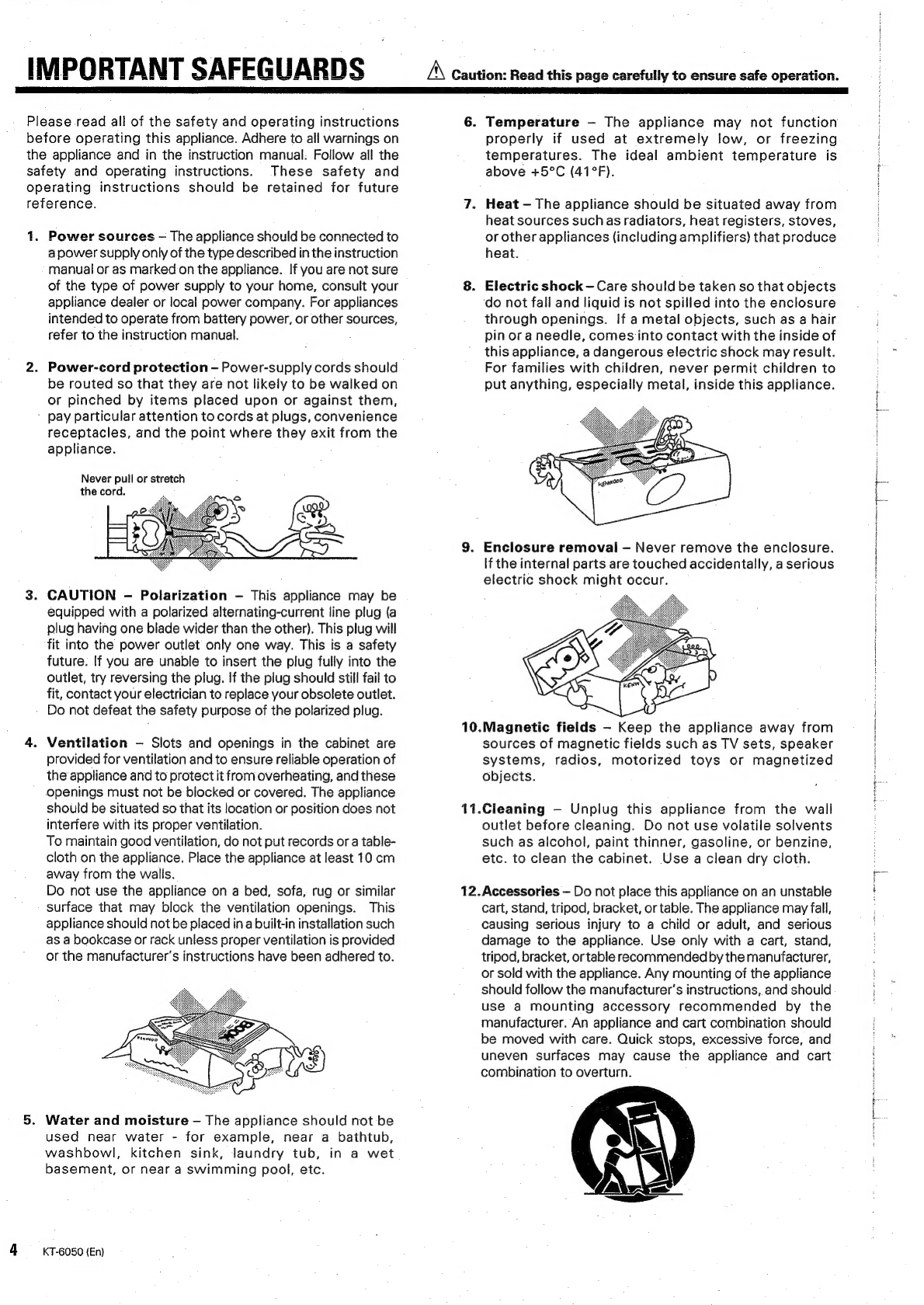
Safety
precautions
A
Caution:
Read
this
page
carefully
to
ensure
safe
operation.
For
Australia
and
Europe
Important!
Units
shipped
to
Australia
are
designed
for
operation
on
240
V
AC
only.
Units
shipped
to
Europe
are
designed
for
operation
on
230
V
AC
only.
For
other
countries
important!
Units
shipped
to
countries
other
than
the
above
countries
are
equipped
with
an
AC
voltage
selector
switch
on
the
rear
panel.
Refer
to
the
following
paragraph
for
the
proper
setting
of
this
switch.
AC
voltage
selection
This
unit
operates
on
110-120
or
220-240
volts
AC.
The
AC
voltage
selector
switch
Type
A
or
Type
B
on
the
rear
panel
is
set
to
the
voltage
that
prevails
in
the
area
to
which
the
unit
is
shipped.
Before
connecting
the
power
cord
to
your
AC
outlet,
make
sure
that
the
setting
position
of
this
switch
matches
your
line
voltage.
If
not,
it
must
be
set
to
your
voltage
in
accordance
with
the
following
direction.
AC
voltage
selector
switch
<_
TypeA
(I
AC110-
«>
AC
220-
120V~
240
V
~
—_—_
—_
Type
B
EERE
UH
AC
110-
120V~
AC
220V~
AC
230-240V~
Move
switch
lever
to
match
your
line
voltage
with
a
small
screwdriver
or
other
pointed
tool.
Note:
Our
warranty
does
not
cover
damage
caused
by
excessive
line
voltage
due
to
improper
setting
of
the
AC
voltage
selector
switch.
WARNING:
TO
PREVENT
FIRE
OR
ELECTRIC
SHOCK,
DO
NOT
EXPOSE
THIS
APPLIANCE
TO
RAIN
OR
MOISTURE.
CAUTION
“RISK
OF
ELECTRIC
SHOCK”
DO.NOT
OPEN
CAUTION:
TO
REDUCE
THE
RISK
OF
ELECTRIC
SHOCK,
DO
NOT
REMOVE
COVER
(OR
BACK).
NO
USER-SERVICEABLE
PARTS
INSIDE,
REFER
SER-
VICING
TO
QUALIFIED
SERVICE
PERSONNEL.
THE
LIGHTNING
FLASH
WITH
ARROWHEAD
SYMBOL,
WITHIN
AN
EQUILATERAL
TRIANGLE,
IS
INTENDED
TO
ALERT
THE
USER
TO
THE
PRESENCE
OF
UNINSULATED
“DANGEROUS
VOL-
TAGE"
WITHIN
THE
PRODUCT'S
ENCLOSURE
THAT
MAY
BE
OF
SUFFICIENT
MAGNITUDE
TO
CONSTITUTE
A
RISK
OF
ELECTRIC
SHOCK
TO
PERSONS.
THE
EXCLAMATION
POINT
WITHIN
AN
EQUILATERAL
TRIANGLE
IS
INTENDED
TO
ALERT
THE
USER
TO
THE
PRESENCE
OF
IMPORTANT
OPERATING
AND
MAINTENANCE
(SERVICING)
IN-
STRUCTIONS
IN
THE
LITERATURE
ACCOMPANYING
THE
APPLIANCE.
KT-6050
(En)
3