
RA 19-1U 041323 i
TABLE OF CONTENTS
SECTION PAGE
SECTION 1 - INTRODUCTION
1.1 Scope of Manual ..................................................................................................................................... 1-1
1.2 General Description................................................................................................................................. 1-1
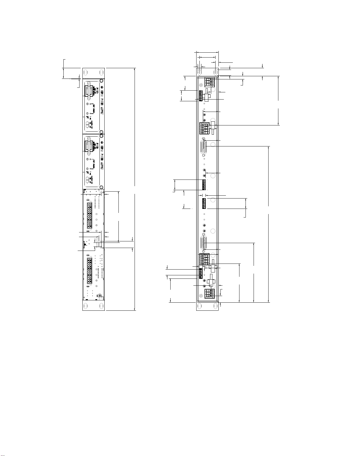
1.3 Mechanical.............................................................................................................................................. 1-1
1.4 Electrical.................................................................................................................................................. 1-1
1.5 Safety...................................................................................................................................................... 1-2
1.6 RoHS Compliance................................................................................................................................... 1-2
1.7 Accessories............................................................................................................................................. 1-3
1.8 Options.................................................................................................................................................... 1-3
SECTION 2 - INSTALLATION
2.1 Unpacking and Inspection....................................................................................................................... 2-1
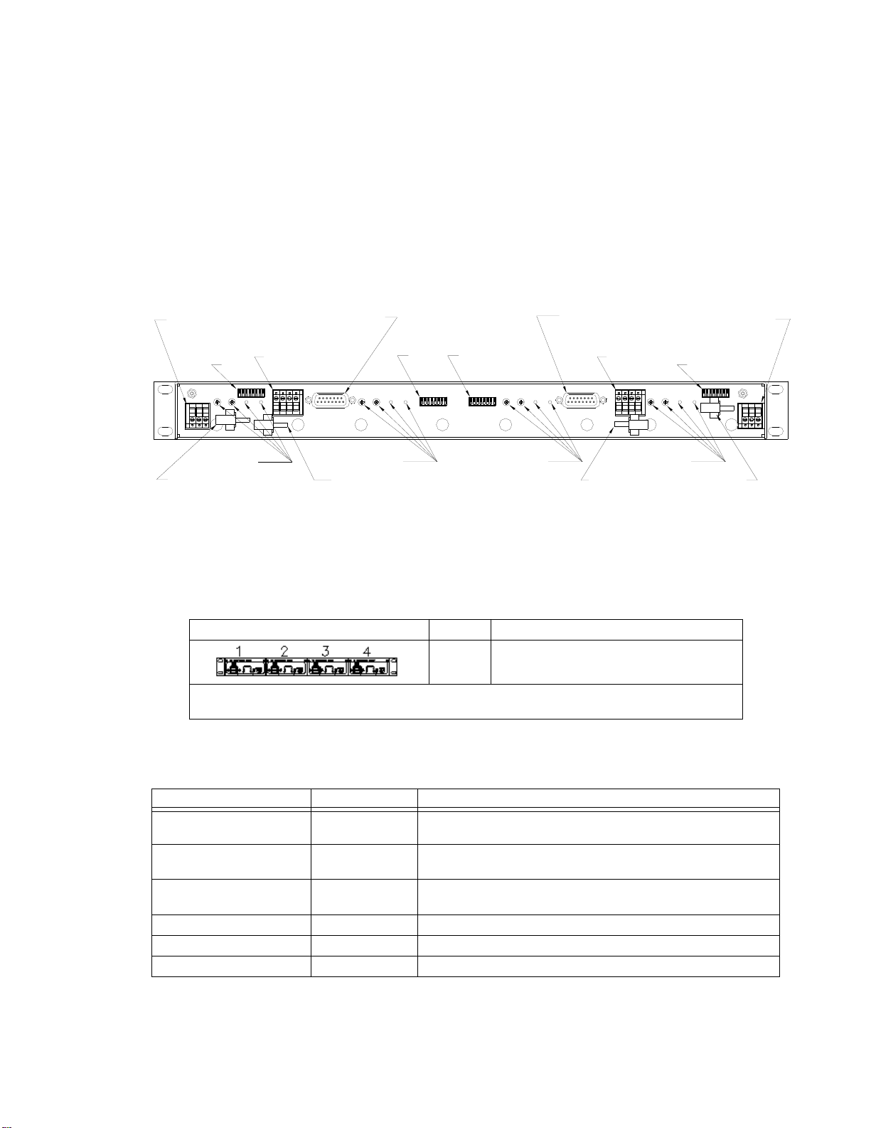
2.2 Configuring the Rack Adapter................................................................................................................. 2-1
2.3 Rack Adapter Keying Instructions ........................................................................................................... 2-1
2.3.1 Establishing Key Positions................................................................................................................. 2-2
2.4 Slot Configuration.................................................................................................................................... 2-2
2.4.1 Independent Operation...................................................................................................................... 2-3
2.4.1.1 Independent Operation - Local Sensing Using Rear Panel DIP switches ................................... 2-4
2.4.1.2 Independent Operation - Local Sensing Using External Wiring................................................... 2-5
2.4.1.3 Independent Operation - Remote Sensing .................................................................................. 2-6
2.4.2 Parallel Operation.............................................................................................................................. 2-7
2.4.2.1 Parallel DC OUTPUT Connections.............................................................................................. 2-7
2.4.2.2 Parallel Current Share Connections ............................................................................................ 2-7
2.4.2.2.1 Parallel Current Share - Rear Panel DIP Switches....................................................................2-8
2.4.2.2.2 Parallel Current Share - External Wiring....................................................................................2-9
2.4.2.3 Sense Connections for Parallel Configurations ........................................................................... 2-10
2.4.2.3.1 Parallel Configuration Using DIP Switches to Connect Sense Lines in
Parallel and External Wires to Configure Local Sensing........................................................2-11
2.4.2.3.2 Parallel Configurations using External Wires to Connect Sense Lines
in Parallel and External Wires to Configure Local Sensing....................................................2-12
2.4.2.3.3 Parallel Configurations using DIP Switches to Connect Sense Lines in
Parallel and External Wires to Configure Remote Sensing....................................................2-13
2.4.2.3.4 Parallel Configurations using External Wires to Connect Sense Lines
in Parallel and External Wires to Configure Remote Sensing................................................2-14
2.4.3 Series Operation................................................................................................................................ 2-15
2.4.4 Alarm Configurations......................................................................................................................... 2-17
2.4.4.1 N.O. Alarm Line (Close on Failure).............................................................................................. 2-17
2.4.4.1.1 Close on Failure Using Rear Panel Dip Switches......................................................................2-17
2.4.4.1.2 Close on Failure Using External Wiring at I/O Mating Connector..............................................2-19
2.4.4.2 N.C. Alarm Line (Open on Failure) .............................................................................................. 2-20
2.4.4.2.1 Open on Failure Using Rear Panel Dip Switches......................................................................2-20
2.4.4.2.2 Open on Failure Using External Wiring of I/O Mating Connector...............................................2-21
2.5 Current Monitoring (-1URC and -1URY Models only) ............................................................................. 2-22
2.6 Remote On-Off (-1URX and -1URY Models only)................................................................................... 2-23
2.7 Terminations............................................................................................................................................ 2-24
2.8 Cooling.................................................................................................................................................... 2-24
2.9 Installation............................................................................................................................................... 2-24
2.9.1 Installing 1U HSF Power Supplies..................................................................................................... 2-24
2.10 Wiring Instructions................................................................................................................................... 2-24


B User manual")


