KEPCO P220 User manual

P220 Printer
User's Manual
990383 06/19/17
KESSLER-ELLIS PRODUCTS
10 Industrial Way East
Eatontown, NJ 07724
800-631-2165 • 732-649-7100
Fax: 732-649-7099


– Page 1 –
DIP Switch Settings
Look at the numbers and letters in the
area indicated in the illustration. If the last
letters are “US”, use the “US” tables below.
If the last letters are “STD”, use the “STD”
tables.
CAUTION:
Be sure to replace the DIP switch cover
before using the printer.
SW Function On Off
1 Printing mode Right side up
printing mode
Normal print-
ing mode
2 Receive buffer capacity 40 bytes 4 KB
3 Handshaking XON/XOFF DTR/DSR
4 Word length 7 bits 8 bits
5 Parity check Yes No
6 Parity selection Even Odd
7 Transmission speed 4800 bps 9600 bps
8BUSY condition Receive buffer
full
Receive
buffer full or
Ofine
US
Serial (DIP Switch 1) Serial (DIP Switch 2)
*: If you set DIP Switch 1-1 to On (Right side up printing mode), make sure to set DIP Switch 1-2 to Off (Receive buffer
capacity: 4 KB).
SW Function On Off
1 Print column 42/35 40/33
2 For internal use only
(autocutter)
Enabled Disabled
3Pin 6 reset signal Used Not used
4Pin 25 reset signal Used Not used
5Undened - -
6 For internal use only
(ash memory rewriting)
Enabled Disabled
7Undened - -
8 Serial interface selection Memory
switch
DIP switch
Serial Interface Settings
Note:
The printer interface settings are set at the factory for communication with KEP Flow
Computers. This provides a "plug-and-play" scenario in which neither the printer nor
ow computer serial interface settings need to be set in order for them to communicate.
If you are connecting the printer to a different device, you may need to change the serial
interface settings for proper communication. Check the required settings of your device
and use the Serial Interface DIP Switch Tables below to change the settings.
Dip Switch Location
1. Locate DIP switch cover on bottom of
printer.
2. Remove screw securing DIP switch cover.
3. Remove DIP Switch cover to access
switches.
DIP Switch Tables
4. Set Switches to desired position.
5. Reinstall cover and reinstall screw snugly.
6. Cycle the power for the new DIP switch
settings to take eect.

– Page 2 –
SW Function On Off
1 Data receive error Ignored Prints “?”
2 Receive buffer capacity 40 bytes 4 KB
3 Handshaking XON/XOFF DTR/DSR
4 Word length 7 bits 8 bits
5 Parity check Yes No
6 Parity selection Even Odd
7 Transmission speed 4800 bps 9600 bps
8BUSY condition Receive buffer
full
Receive buf-
fer full or
Ofine
STD
Serial (DIP Switch 1) Serial (DIP Switch 2)
SW Function On Off
1 Print column 42/35 40/33
2For internal use only
(autocutter) Enabled Disabled
3Undened - -
4 Serial interface selection Memory switch DIP switch
5Undened - -
6For internal use only
(ash memory rewriting)
Enabled Disabled
7 Pin 6 reset signal Used Not used
8 Pin 25 reset signal Used Not used
25 pin D-SUB
female connector
on printer
12345
6789
9 pin D-SUB female
connector at KEP
ow computer (FC)
Printer Pin
Number
Printer
Pin Name
2 TXD
3 RXD
6 DSR
7 Ground
20 DTR
5 CTS
4RTS
FC Pin
Number
FC Pin
Name
1 CTS
2 TXD
3 RXD
5 Ground
7RTS
Serial Port Connectors
Panel Mount ST2 Series Wall Mount
25 pin D-SUB
female connector
on printer
6 pin terminal block
connector at KEP
ow computer (FC)
Printer Pin
Number
Printer
Pin Name
2 TXD
3 RXD
6 DSR
7 Ground
20 DTR
5 CTS
4RTS
FC Pin
Number
FC Pin
Name
1 TXD
2 RXD
3 Ground
4 Bias
5 CTS
6MP (+8V)
Typical Cable Connections
DB25 DB9
2 1
3 2
4 3
7 5
DB25 TB
2 1
3 2
4 3
7 5

– Page 3 –
Serial Port Connectors
MS716
25 pin D-SUB
female connector
on printer
6 pin terminal block
connector at KEP
ow computer (FC)
Printer Pin
Number
Printer
Pin Name
2 TXD
3 RXD
6 DSR
7 Ground
20 DTR
5 CTS
4RTS
FC Pin
Number
FC Pin
Name
1 TXD
2 RXD
3 Ground
4 MP
5 CTS
6 Do Not
Use
MS748
25 pin D-SUB
female connector
on printer
6 pin terminal block
connector at KEP
ow computer (FC)
Printer Pin
Number
Printer
Pin Name
2 TXD
3 RXD
6 DSR
7 Ground
20 DTR
5 CTS
4RTS
FC Pin
Number
FC Pin
Name
1 TXD
2 RXD
3 Ground
4 Bias
5 CTS
6MP (+8V)
ST1 Series Wall Mount
25 pin D-SUB
female connector
on printer
6 pin terminal block
connector at KEP
ow computer (FC)
Printer Pin
Number
Printer
Pin Name
2 TXD
3 RXD
6 DSR
7 Ground
20 DTR
5 CTS
4RTS
FC Pin
Number
FC Pin
Name
1 TXD
2 RXD
3 Ground
4 MP
5 CTS
6 Do Not
Use
Typical Cable Connections
DB25 TB
2 1
3 2
4 3
7 5

– Page 4 –
P220 Specications
dpi: dots per 25.4 mm (dots per inch); lps: lines per second; lpi: lines per 25.4 mm (lines per inch)
*1: Be sure to use a safety-standards-applied power source that meets the following specications.
Rated output: 24 V/2.0 A or more, Maximum output: 240 VA or less
Printing method 9-pin serial impact dot matrix method
Print font Font (standard) Font A: 7 × 9, Font B: 9 × 9
Column capacity
(columns)
7 × 9/9 × 9:
76 mm: 40/33
69.5 mm: 36/30
57.5 mm: 30/25
Character size (W ×H)
(standard)
1.2 × 3.1 mm/1.6 × 3.1 mm (not including horizontal spacing)
Character set 95 Alphanumeric, 48 International,128 × 12 Graphic
Characters per inch
(standard)
(3 half dot spacing)
Font A (7 × 9): 16 cpi, Font B (9 × 9): 13.3 cpi
Paper Dimensions (mm) 57.5 ±0.5, 69.5 ±0.5,
76 ±0.5
Normal paper (mm) Thickness: 0.06~0.085 (1 sheet)
Pressure-sensetive paper Thickness: 0.05~0.08 (1 sheet), total thickness must be 0.14
mm or less.
Number of copies: Original 1 sheet + one copy sheet
Ribbon cassettes ERC-38 (B) Black life: 3,000,000 characters
ERC-38 (B/R) Black/Red life: Black 1,500,000/Red
750,000 characters
Life based on continuous printing at 25°C {77°F}
Printing speed (Paper width 76 mm) 4.7 lps (40 columns, 16 cpi)
Interface RS-232 or IEEE 1284
Receive buffer 4 KB or 40 bytes
Power supply*1 24 VDC ±7%
Cash drawer function 2drives
Temperature Operating 0~50°C
Storage –10~50°C, without paper and ribbon cassette
Humidity Operating 10~90%, must be no condensation
Storage 10~90%, must be no condensation, without paper and ribbon
cassette
Overall dimensions (mm) 160 × 248 × 138.5 (W × D × H)
Mass (approx.) 2.3 kg

– Page 5 –
Important Safety Information
This section presents important information intended to ensure safe
and eective use of this product. Read this section carefully and store
it in an accessible location.
Key to Symbols
The symbols in this manual are identied by their level of importance,
as dened below. Read the following carefully before handling the
product.
WARNING:
Warnings must be followed carefully to avoid serious bodily injury.
CAUTION:
Cautions must be observed to avoid minor injury to yourself or damage to your
equipment.
Safety Precautions
WARNING:
Shut down your equipment immediately if it produces smoke, a strange odor, or
unusual noise. Continued use may lead to re. Immediately unplug the equip-
ment and contact your dealer or a service center for advice.
Never attempt to repair this product yourself. Improper repair work can be dan-
gerous.
Never disassemble or modify this product. Tampering with this product may
result in injury or re.
Be sure to use the specied power source. Connection to an improper power
source may cause re.
Do not allow foreign matter to fall into the equipment. Penetration by foreign
objects may lead to re.
If water or other liquid spills into this equipment, do not continue to use it. Con-
tinued use may lead to re. Unplug the power cord immediately and contact your
dealer or a service center for advice.
If you open the DIP switch cover, be sure to close the cover and tighten the screw
after adjusting the DIP switch. Using this product with the cover open may cause
re or electric shock.
Do not use aerosol sprayers containing ammable gas inside or around this
product. Doing so may cause re.

– Page 6 –
CAUTION:
Do not connect cables in ways other than those mentioned in this manual.
Different connections may cause equipment damage and burning. Be sure to set
this equipment on a rm, stable, horizontal surface. Product may break or cause
injury if it falls.
Do not use in locations subject to high humidity or dust levels. Excessive humid-
ity and dust may cause equipment damage or re.
Do not place heavy objects on top of this product. Never stand or lean on this
product. Equipment may fall or collapse, causing breakage and possible injury.
Take care not to injure your ngers on the manual cutter
• When you remove printed paper
• When you perform other operations such as loading/replacing roll paper
To ensure safety, unplug this product before leaving it unused for an extended
period.
Before moving the product, unplug it and unplug all cables connected to it.
Safety Label
The caution labels on the product indicate the following precautions.
WARNING:
Do not connect a telephone line to the drawer kick out connector; other-
wise, the printer and the telephone line may be damaged.
CAUTION:
During printing or after printing, the print head can be very hot.
Notes on Usage
❏Do not install the printer in a dusty place.
❏Protect the printer from impact.
❏Cords or other foreign objects must not be caught on the printer.
❏Do not apply excessive force to the printer case.
❏ Do not place food or beverages such as coee on the case of the
printer.
Notes on Installation
❏When using the printer, be sure that the printer is installed hori-
zontally.

– Page 7 –
❏Wall Mount option is available, you can hang it on a wall, using
the optional hanging bracket set, P220WMB.
Note:
To hang the printer on a wall, see Appendix A at end of this manual.
Notes on Connecting the Power Supply Unit
Be sure to use the correct power supply unit as listed below:
Note:
The “AC adapter, C,” which is packed with the alphanumeric model, cannot
be used with the multilingual* model. Be sure to use the “PS-180” with the
multilingual* model. If the “AC adapter, C,” packed with the alphanumeric
model, is connected to the multilingual* model by mistake, the printer might
not operate correctly. For example, printing might stop before all the lines are
printed or the printer might print the same line repeatedly.
*Multilingual means the printer model that can print any one of the following: Japanese Kanji, Simplied
Chinese, Traditional Chinese, Thai characters, or Korean characters.
Purpose of This Manual
This manual provides information to operators of the P220 to describe
basic operations to enable safe and correct use of the printer.
Restriction of Use
When this product is used for applications requiring high reliability/
safety, such as transportation devices related to aviation, rail, marine,
automotive, etc.; disaster prevention devices; various safety devices,
etc.; or functional/precision devices, etc.; you should use this product
only after giving consideration to including fail-safes and redundan-
cies into your design to maintain safety and total system reliability.
Because this product was not intended for use in applications requir-
ing extremely high reliability/safety, such as aerospace equipment,
main communication equipment, nuclear power control equipment,
or medical equipment related to direct medical care, etc., please make
your own judgment on this product’s suitability after a full evaluation.
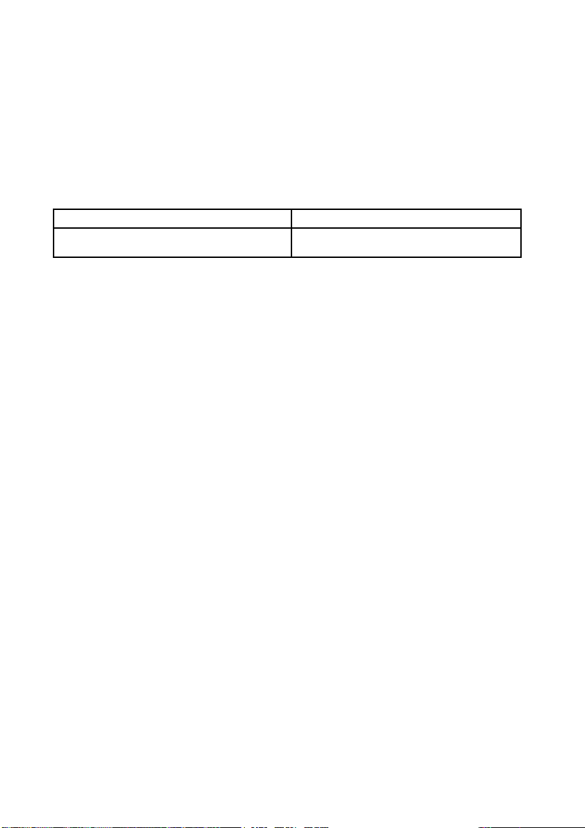
P220 alphanumeric model P220 multilingual* model
“AC adapter, C” (packed with the alphanumeric model)
or “PS-180” (option)
“PS-180” (packed with the multilingual* model)

– Page 8 –
Unpacking
The following items are included for the standard specication printer. If any
item is damaged, contact your dealer.
❏Printer
❏Roll paper
❏Exclusive ribbon cassette [ERC-38]
❏AC adapter (May not be included with the printer.)
Control Panel (LEDs and Buttons)
See illustration B.
LEDs
POWER (POWER)
Lights when the power is on and is o when the power is o.
ERROR (ERROR)
Lights when the printer is oine (when the roll paper is at the end, or
the roll paper cover is open). O when the printer operates correctly.
Flashes when an error occurs. (See the Troubleshooting section.)
PAPER OUT (PAPER OUT)
Lights when roll paper is out or nearly out.
Buttons
FEED (FEED)
FEED (FEED) feeds the roll paper.
Note:
Paper cannot be fed by using this button when a paper out is detected.
A B
1
3 4 2
1. Roll paper
cover
2. Ribbon cassette
cover
3. Control panel
4. Power supply
switch

– Page 9 –
Power Supply Switch and Power Supply Switch Cover
The power supply switch is on the front of the printer. Press the power supply
switch to turn on the printer.
Power Supply Switch Cover
You can use the enclosed power supply switch cover to make sure that the
power supply switch is not accidentally pressed. Just press the cover into
place to install it. If you need to turn the power supply switch on or o with
the cover attached, you can insert a thin tool into one of the holes in the cover
to operate the switch. See illustration C.
WARNING:
If an accident occurs when the power supply switch cover is attached, immediately un-
plug the power supply cable to avoid re.
If you are going to store the printer or leave it unused for a long time, turn it
o using the power supply switch on the printer.
C

– Page 10 –
Inserting and Replacing the Ribbon Cassette
CAUTION:
The print head becomes very hot during printing. Allow it to cool before you replace the
ribbon cassette.
CAUTION:
Never turn the ribbon cassette’s feed knob in the opposite direction of the arrow marked
on the cassette; otherwise the ribbon cassette may be damaged.
Note:
1. Open the ribbon cassette cover by using the tabs on the sides of the cover,
as shown in illustration D.
2. Turn the knob two or three times in the direction of the arrow, as shown in
illustration E.
3. Insert the ribbon in the position shown in illustration F and push
the ribbon cassette down until it clicks.
Note:
Make sure the ribbon is installed between the print head and the platen without wrin-
kles or creases.
DE
F 4. Again turn the ribbon cassette’s knob
2 or 3 times in the direction
of the arrow and close the ribbon cas-
sette cover.
CAUTION:
Be careful not to touch the print head with your
ngers when turning the ribbon cassette knob
because the print head is hot and you might be
burned.
When you replace the ribbon cassette, lift the
left side of the ribbon cassette rst; then lift
the whole ribbon cassette.

– Page 11 –
Inserting Roll Paper
CAUTION:
Be sure to use roll paper that meets the specications.
Be sure not to touch the manual cutter. Otherwise your ngers might be injured.
1. Using scissors, cut the leading edge of the roll paper, as shown in illustra-
tion G.
2. Turn on the printer and open the roll paper cover by using the tab, as
shown in illustration H.
3. Insert the roll paper, as shown in illustration J.
Note:
Note the direction the paper comes o the roll, as shown in the illustration G.
When using 2-ply roll paper, be sure that the top and bottom sheets are aligned at the
paper exit. See illustration G-a.
5. Pull out a small amount of roll paper and close the roll paper cover; then
tear o the paper with the manual cutter.
G-a
H
G
Note:
Do not open the roll paper cover during printing or paper feeding.
When using the printer, be sure to cut the roll paper with the manual cutter after
paper feeding is complete.
J

– Page 12 –
Replacing Roll Paper
1. Open the roll paper cover by using the tab, as shown in illustration H.
2. Remove the used roll paper core.
3. Insert new roll paper. See the section “Inserting Roll Paper”.
H

– Page 13 –
ERROR (ERROR) LED is ashing or lit
❏The print head temperature may be too high or low. Wait until the
print head cools or warms and the printer resumes printing auto-
matically.
❏Make sure that the roll paper cover is properly closed.
❏A paper jam has occurred. To remove the jammed paper, see the
instructions below.
❏ Turn o the power, wait several seconds, and then turn it on again.
If the error remains, contact your supervisor or a qualied service
person.
Removing jammed paper
CAUTION:
The print head becomes very hot during printing. Allow it to cool before you
reach into the printer.
1. Open the roll paper cover by using the tab, as shown in
illustration H. (Page 11)
2. Remove the jammed paper.
3. Re-insert the roll paper and close the roll paper cover.
*Multilingual means the printer model that can print any one of the following: Japanese Kanji, Simplied
Chinese, Traditional Chinese, Thai characters, or Korean characters.
No lights on the control panel
Check the power supply cable connections and the power outlet.
The power supply unit that can be used with the
P220 alphanumeric model
The power supply unit that can be used with the
P220 multilingual* model
“AC adapter, C” (packed with the alphanumeric model)
or “PS-180” (option)
“PS-180” (packed with the multilingual* model)
Troubleshooting
Printing stops before all the lines are printed or the printer prints the same line
repeatedly
If the correct power supply unit is not used, the printer cannot operate cor-
rectly. Make sure the correct power supply unit is connected to the printer,
referring to the table below:

– Page 14 –
Ordering Information:
EXAMPLE P220 N
Series
P220 Impact Receipt Printer
Options
N = NEMA 4X Wall Mount Enclosure with sub-panel
& duplex outlet
Accessories
P220WMB = Wall Mount Bracket for P220 Printer
P2CA25M9ML6 = 6’ Serial Cable for SUPERtrol I, SUPERtrol ILE,
LEVELtrol II, SUPERtrol II
P2CA25MFLL6 = 6’ Serial Cable for MS716 or any Flow Computer
with RS232 terminal block
P220PR-1P = Paper Roll for P220 Printer; Single-ply Impact 3"
width x 165' length, Single roll.
P220PR-2P = Paper Roll for P220 Printer; Two-ply Impact, 3"
width x 100' length. 1st copy is white, 2nd copy is
yellow. Single roll.
P220INK-B = Black Ink Fabric Ribbon
PC12-24DC = Power Converter 12VDC input, 24VDC output
Warranty:
Two-year limited warranty in the U.S. and Canada

– Page 15 –
1
2
4
3
4 1
3
2
1
2
4
3
4 1
3
2
Appendix A
How to Install the Printer on a Wall with the P220WMB
P220WMB is a option for the P220 printer, with it you can install a P220 on a wall. This section
describes how to install wall hanging P220.
A.1 The Procedure
A.1.1 Precautions
❏Static electricity may cause cut paper to adhere to the printer case.
(This static electricity will not aect the operation of the printer.)
A.1.2 Unpacking
Open the package and conrm that it contains all of the parts listed in the illustration. If any
parts are missing or damaged, please contact your dealer for assistance.
wall-mount (note: screws for
wall-mount not included; see the
installation section.) brackets (2 pieces)
screws for brackets (3×12)
(4 pieces)
roll paper holder for
hanging bracket
cam
control panel sheets
Please attach the appropriate sheet.
screws (3×10) screws (3×6) (5 pieces) Note:
4 of the screws are used for
attaching the brackets
Depending on the conditions during storage and shipping, some rust may form around the
edges of the wall-mount or brackets. This may be removed with sandpaper.

– Page 16 –
A
84mm
48mm
A.1.3 Installation
Before installation, be sure that the printer and all equipment connected to the printer is turned
o. Detach all cables from the body of the printer.
A.1.3.1 Installing the wall-mount
CAUTION:
The weight of the printer is approx. 2.3 kg. In order to insure that the wall-mount can properly support
the weight of the printer, please secure it with screws appropriate to the type of wall the wall-mount is
installed on. A screw with 4 mm diameter and length of 12 mm or more is recommended. The thickness of
the wall should be 10 mm or more.
Be sure to fasten the wall-mount securely to the wall with a screw in each of the ten holes.
Before attaching the wall-mount, make sure enough space remains
around the printer.
Make sure that there is enough space for opening the printer cover.
Attach the wall-mount to the wall in the position illustrated to the right
(with the area marked A at the top), and fasten securely with ten screws.
These screws are not included; please use screws appropriate to the type
of wall being used.
A.1.4 Afxing the operation panel sheet
When you mount the printer on the wall, the operation panel on the printer will be upside
down. Therefore, operation panel sheets in the correct direction for wall mounting have been
enclosed.
Align the FEED switch mark on the operation panel sheet with the FEED switch mark on the
printer operation panel and ax the operation panel sheet to the printer.
A.1.5 Changing the roll-paper detector position
Two types of screws are used with the P220WMB: 3×6 and 3×10. The longest screw (3×12) will
not be used.
1. Open the roll paper cover.
For a model that does not have a roll-paper near-end detector and does not need a change in
paper width, jump to step 7. For a model that does not have a roll-paper near-end detector
and needs a change in paper width, jump to step 3

– Page 17 –
cable
2. Loosen the detector adjustment screw a little bit by using a tool such as a coin and then
loosen the screw gently by hand as until it stops. It must not be removed completely.
detector ad-
justment screw
3. Remove the two screws of the roll paper guide.
roll paper
guide
For a model that does not have a roll-paper near-end detector , jump to step 6.
4. Rotate the detector lever on the roll paper guide to change its direction.
Note:
After the direction of the detector lever is changed, be sure that the cable is connected to the connector
rmly.
detector lever
5. Tighten the detector adjustment screw.
6. Align the hole on the roll paper guide with the hole on the roll paper holder to match your
roll paper width and then tighten the screw (3×10).
Note:
You will not use one of the two screws that have been removed when the roll paper guide is removed.
Please store it as an extra screw in case you need it.

– Page 18 –
76 mm 70 mm 58 mm
holder
dowel
hole
roll paper
guide
roll paper
7. Align the hole on the roll paper holder for hanging bracket with the dowel on the roll paper
guide. (For a model that needs a change of paper width, the hole to be used will be dierent
to match your roll paper width.)
Putting the screw (3×6) in the hole on the roll paper holder for hanging bracket makes it
easier for you to tighten the screw in the next step.
76 mm 70 mm 58 mm
roll paper holder for
hanging bracket
8. Tighten the screw (3×6) to x the roll paper holder for hanging bracket and the base frame.
Table of contents
Other KEPCO Printer manuals