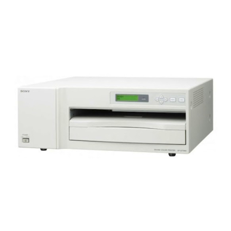
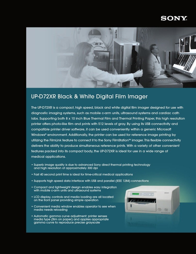
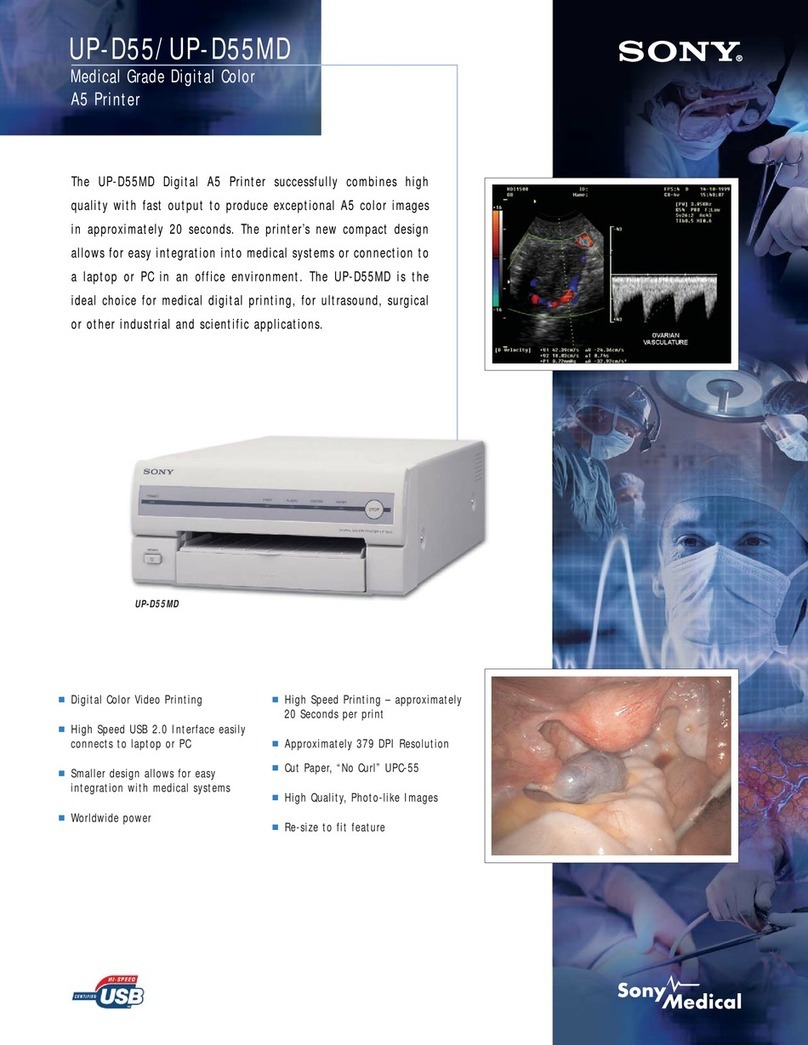
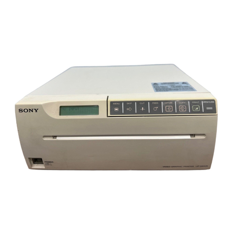
Sony UP-890CE User manual

SONTYTY.
UP-890CE
UP-890MD
SERVICE
MANUAL

AFETY
RELATED
COMPONENT
WARNING
Components
identified
by
shading
and
A
marked
on
the
schematic
diagrams
and
parts
list
are
critical
to
safe
operation.
Replace
these
components
with
SONY
parts
whose
part
numbers
appear
as
shown
in
this
manual
or
in
supplements
published
by
SONY.

CONTENTS
Section
Page
1.
GENERAL
1-1.
Specifications...
ecseecetereereretseensseneneneeneeees
4
1-2.
Location
and
Function
of
Parts...
5
1-8.
OVOPVIOW
0...
ecececeeteesreennseenseesennaeesnaeeaaenecsensnaeteas
6
1-4.
COMMECTION
2.0...
eee
eeeeseetesereeneeseeeneeeteatenssesenseenee
6
1-5.
Before
Printing
............eseseeeseeseeerenectseeseeseseeee
7
1-6.
Loading
Paper...
cceseseeeseeereeseseenenseeeneeneens
9
1-7.
PIMtING.
oo.
eee
eects
eeceteeeeeseneeteeeetenensensnsentnseenenees
10
1-8.
PreCAUtiONS
.......
ee
sceeeceeeeeseeceaseeeenteseecenenssens
12
1-9.
On
the
Type
of
Paper...
ceeseseeeteeeteees
13
1-10.
Troubleshooting
..........ccccceeeseseeseeetereeeseeerecees
14
2.
DISASSEMBLY
2-1.
Removing
the
Top
Cover........eecrscesececceses
15
2-2.
Removing
the
Door
Panel
and
Front
Panel
Unit...
esessscssseesseeerseseeereseees
15
2-3.
Removing
the
MA-19
Board.........
cess
16
2-4.
Removing
the
Mechanism
Block
.................+
16
2-5.
Removing
the
Shield
Case
and
Switching
ReQulator
...........cccecceeeessnseeeeeseees
17
2-6.
Removing
the
Thermal
Head
.............
18
3.
ADJUSTMENTS
3-1.
Head
Voltage
Adjustment...
eessesecsees
19
3-2.
Brightness
Contrast
Adjustment...............:+
19
3-3.
Motor
Speed
Adjustment
..........--ceeeeeeetees
20
4.
DIAGRAMS
4-1.
Circuit
Boards
Location
.........
cesses:
21
4-2.
BlOCK
DiaQrarn
.........cccesesceceteeeneeeteseeeneteesnenes
22
4-3.
Printed
Wiring
Boards
and
Schematic
Diagrams
...........sseeeseseeeeerereerees
25
4-4,
S@MICONAUCTOSS
«0...
ce
eeeseesereereeteetecseneeeneeeees
39
Section
Page
5.
CIRCUIT
DESCRIPTION
5-1.
Video
Circuit...
ees
ssseceeesneenteeseretseneeerseee
46
5-5-1.
Operation
........ceccsssscsessecsecerenenseesssensenneneees
46
5-2.
Oscillation
Circuit
0...
eseeesceeereesneeneeenees
47
5-3.
Peripheral
Circuit
10103
............ceseseeeeeees
48
5-3-1.
Operation
description
...........ceeeesereesees
48
5-4.
System
Control
Section
..........eecseseeeeeneees
51
5-4-1.
Memory
write
(FETCH)
signals
from
the
Print
KOY....eceseeteeeteneeetsatensenees
51
5-4-2.
From
memory
writing
till
screen
PIII
0...
eeesessceeceetenencceeenetenentenseereesoneens
52
5-4-3.
MOE
St
on.
.ceecesesccssccesssnceeesssneeseserereerssensaees
54
5-5.
Motor
Drive
S@ction
0.0...
cccesesscesseseeseennersees
55
5-5-1.
Platem
Motor
ou...
cceecesscccessseeeentesterereeteeeens
55
5-5-2.
Head
U/D
motor
and
DOOR
motor........
55
5-6.
Thermal
Head
Section
...........cesessseereceseees
56
5-6-1.
COnmfiguration
.........ccsccseseeesssereeeeseerersesateres
56
5-6-2.
Timing
Chatto...
.cesseseseseneeeeeereecectseenees
56
5-6-3.
Basic
OPeration
ou...
ccsceceescrerereereeereseneees
57
5-6-4.
Stair
GENeration
20...
eccecseeeenesteeseeeeees
57
5-6-5.
Temperature
compensation..........seee
58
6.
EXPLODED
VIEWS
6-1.
Chassis
S@CtiON
00...
ccscsseeseteeeteecerrteeeseseees
59
6-2.
Print
Mechanism
Section
(1)...
61
6-3.
Print
Mechanism
Section
(2)...
63
7.
ELECTRICAL
PARTS
LIST
.............:
ee
65

F
UP-890CE/890MD
SECTION
1
GENERAL
1-1.
SPECIFICATIONS
Thermal
head
Thin-film
thermal
head
(with
built-in
drive
IC)
1024-dot
drive
Gradation
256
Resolution
(in
WIDE
|
mode)
EIA:
970
x
490
dots
CCIR:
970
x
582
dots
Print
size
(in
NORM
and
WIDE
|
mode)
STD
mode
EIA:
95
x
72
mm
CCIR:
95
x
71
mm
SIDE mode
EIA:
127
x
96
mm
CCIR:
127
x
95
mm
Printing
speed
(in
STD
and
NORM
mode)
About
3.9
seconds/screen
(aspect
ratio
4:3)
Picture
memory
786
K
x
6
bits
InpuVoutput
connectors
VIDEO
IN
(BNC)
EIA
or
CCIR
Composite
video
signals
1.0
Vp-p,
75
ohms/high-impedance
(EIA/
CCIR
automatically
discriminated)
VIDEO
OUT
(BNC)
EIA
or
CCIR
Composite
video
signals
1.0
Vp-p,
75
ohms,
loop-through/EE
switchable
REMOTE
(stereo
minijack)
“8
ii
1
|
GND
2
PRINT
SIGNAL
(TTL)
Input
of
LOW
pulse
over
100
msec.
initiates
print.
3
PRINT
BUSY
(TTL)
Goes
HIGH
during
printing.
20
|
Others
This
section
is
extracted
from
instruction
manual.
Power
requirements
and
consumption
120
V
AC,
50/60
Hz,
1.5
A
(UP-890MD)
220
to
240
V
AC,
50/60
Hz,
0.8
A
(UP-890CE)
Dimensions
Approx.
[54
x
106
x
303
mm
(w/h/d)
(6%
x
4%
x
12
inches)
Mass
Approx.
3.5
kg
(7
Ib
11
oz),
Main
unit
only
Supplied
accessories
Paper
roll
(UPP-1
LOHA)
(1)
BNC
-
BNC
connecting
cable
(1)
AC
power
cord
(1)
Head
cleaning
sheet
(1)
Remote
commander
RM-91
(1)
supplied
with
UP-890MD
only
Design
and
specifications
are
subject
to
change
without
notice.

1-2.
LOCATION
AND
FUNCTION
OF
PARTS
For
details,
refer
to
the
pages
indicated
in
parentheses.
{1]
Power
ON/OFF
switch
and
indicator
Turns
the
power
on.
The
indicator
is
tit
while
the
power
is
on.
CS)
Printing
size
selector
(13)
Selects
the
printing
size.
STD
(standard)/SIDE
selector
(13)
Selects
the
printing
direction.
&e
CONTR
(contrast)
control
(15)
Adjusts
the
contrast
of
the
print-outs.
@
THRU/EE
selector
(15)
Selects
the
video
signal
output
from
the
VIDEO
OUT
connector.
THRU:
Input
signals
are
directly
output
to
the
video
monitor.
FE:
Input
signals
are
output
to
the
video
monitor
after
being
processed
by
the
printer's
circuitry.
Others
[6]
BRIGHT
(brightness)
control
(15)
Adjusts
the
brightness
of
the
print-outs.
COPY
button
(14)
Prints
another
copy
of
the
previous
print-out.
PRINT
button
(12)
Prints
the
picture
currently
displayed
on
the
video
monitor.
The
picture
displayed
when
you
press
the
PRINT
button
is
stored
in
memory.
(9)
PAPER
EMPTY
indicator
Lights
when
the
printer
is
out
of
paper.
OPEN/CLOSE
button
(10,
14)
Opens
or
closes
the
door.
Also,
stops
printing
midway.
iy)
Paper
feeder
and
cutter
Cuts
the
printing
paper.
REMOTE
connector
(5)
Connect
the
RM-¥91
remote
commander
for
controlling
print
operation
from
a
distance.
The
RM-91
remote
commander
is
supplied
with
UP-890MD
only.
GAMMA
selector
(6)
Changes
the
print
mode
to
that
for
high-
density
printing
paper.
The
selector
is
effective
when
the
PAPER
TYPE
selector
is
set
to
Tlor1V.
{os}
PAPER
TYPE
selector
(6)
Sets
the
type
of
paper.
[4]
DIP
SW
(switches)
(7
-
9)
Sets
the
print
modes
and
functions.
VIDEO
IN
(input)
connector
(BNC
type)
(5)
Connect
to
the
video
output
connector
of
the
video
equipment.
[6]
VIDEO
OUT
(output)
connector
(BNC
type)
(5)
Connect
to
the
video
input
connector
of
the
video
monitor.
The
output
signal
type
depends
on
the
setting
of
the
THRU/EE
selector.
AC
IN
(AC
power
input)
connector
(5)
Connect
to
a
wall
outict
using
the
supplied
AC
power
cord.
Equipotential
terminal
Fquipped
only
with
the
UP-890CE/890MD.
Others
|
23

4
1-3.
OVERVIEW
Introduction
The
UP-880/890CE/890MD
is
a
black
and
white
video
graphic
printer
that
can
be
used
to
print
images
displayed
on
video
monitor.
Clear,
consistent
print
quality
*
High
definition,
10.2
dots/mm
printing
using
a
thermal
head
with
high-speed
drive
IC.
*
256
gradations
of
black
and
white.
Fast
printing
*
You
can
make
a
single
print-out
in
about
3.9
seconds
in
STD
and
NORM
mode.
*
You
can
make
a
maximum
of
11
copies
of
the
same
image
continuously.
Two
way
printing
direction
and
five
printing
sizes
selectable
*
The
printing
direction
selector
on
the
front
panel
enables
you
lo
print
in
vertical
and
horizontal
directions.
¢
The
printing
size
control
on
the
front
panel
enables
you
to
select
five
kinds
of
printing
size.
DIP
switches
to
optimize
the
printer
*
You
can
make
print-outs
starting
either
from
the
bottom
or
top
of
the
image
by
setting
the
DIRECTION
DIP
switch.
*
You
can
set
the
print-out
aspect
ratio
to
4:3
or
1:1
by
setting
the
ASPECT
DIP
switch.
*
You
can
set
the
range
to
be
printed
by
setting
the
SCAN
DIP
switch.
*
You
can
save
your
paper
by
setting
the
POSTFEED
DIP
switch
(paper
saving
function).
Automatic
video
signal
discrimination
The
type
of
input
signal,
black
and
white
(EIA
or
CCIR)
or
input color
(NTSC
or
PAL),
is
automatically
discriminated
and
printed
in
same
duration
and
size.
Alarm
buzzer
The
alarm
buzzer
prevents
you
from
making
any
misopcration.
Easy
and
quick
paper
loading
You
can
load
paper
just
by
opening
the
paper
lid
with
the
OPEN/CLOSE
button
and
placing
the
paper
roll.
1-4.
CONNECTION
*
Turn
off
the
power
to
each
device
before
making
connection.
*
Connect
the
AC
power
cord
fast.
RM-91
remote
Color/lack
and
white
commander”
e
video
monitor
Video
equipment
to
video
oulput
Connecting
cable
connector
(not
supplied)
Supplied
coaxial
to
video
input
connecting
cable
connector
(BNG
—+
BNC)
to
REMOTE
lo
VIDEO
IN
Px
=
10
VIDEO
OUT
to
AC
IN
fo
wall
outlet
Supplied
AC
power
cord
*
The
RM-91
remote
commander
is
supplied
with
UP-890MD
only.
Preparation
5

1-5.
BEFORE
PRINTING
LLL
aaa
OT
Ee
A
eT
Setting
the
Type
of
Paper
Setting
the
DIP
Switches
Set
the
PAPER
TYPE
selector
to
the
type
of
paper
to
be
used.
Set
the
DIP
switches
according
to
the
required
print
mode.
Before
setting
the
DIP
‘The
use
of
paper
other
than
Sony
may
result
in
reduced
printer
performance
and
switches,
turn
the
power
off,
Change
the
settings
using
a
small
pointed
tool
such
as
poor
print
quality.
a
small
screwdriver.
The
factory
settings
are
as
follows.
Type
of
paper
PAPER
TYPE
switch
position
UPP-110S
|
(Normal)
UPP-110HD
Il
(High
density)
UPP-110HA
!V
(Enhanced)
on
Parti
oor
AtMore
i
onew
NN
i
APER
P
<-viDEO—
GAMMA
TYPE
Louw
Luv
SW-ON|SW-OFF
O
OFF
FEED
[ON
[OFF
|
When
you
use
the
UPP-110HA
or
UPP-110HD
ERRUEFONGEE
Seal
When
you
set
the
PAPER
TYPE
selector
to
I
or
IV,
set
the
density
gradation
with
To
interrupt
the
printing
under
way
and
print
a
new
picture
when
you
press
the
GAMMA
selector.
the
PRINT
button
during
printing,
set
this
switch
to
ON.
1:
Soft
gradation
To
disregard
that
the
PRINT
button
is
pressed
during
printing
and
continue
Hi:
Standard
the
printing
under
way,
set
to
OFF.
IV:
Hard
gradation
If
you
press
the
PRINT
button
during
printing
in
OFF
mode,
the
alarm
buzzer
will
sound.
[2]
POSTFEED
ON/OFF
switch
To
feed
out
extra
blank
paper
once
a
picture
has
been
printed,
set
this
switch
to
ON.
To
save
paper
by
feeding
only
a
short
length
of
paper
after
printing
a
picture,
set
(o
OFF.
You
can
make
more
print-outs
per
roll
of
printing
paper,
but
you
have
to
take
out
and
cut
the
paper
yourself,
6
|
Preparation
Preparation
|
7

er
ASPECT
4:3/1:1
switch
(8][9]
SCAN
NORM/WIDE
I/WIDE
2
switch
Normally
keep
this
switch
set
to
4:3.
When
the
aspect
ratio
of
the
vidco
Sets
the
print-out
range.
The
print-out
range
is
widened
in
the
NORM,
WIDE
signal
is
1:1,
set
to
Ist.
1,
and
WIDE
2
order.
The
print-out
will
be
longer
than
a
print-oul
made
at
4:3.
To
print
only
the
image
displayed
on
the
standard
screen
size
of
the
video
monitor,
set
the
SCAN
switch
[9]
to
NORM
(OFF).
To
print
when
the
signal
scans
beyond
the
edge
of
the
standard
monitor
screen,
set
the
SCAN
switch
[9]
10
WIDE
1
(ON)
or
the
SCAN
switch
[8]
to
WIDE
2
(OFF).
When
you
set
the
SCAN
switch
{8]
to
the
WIDE
2
position,
WIDE
2
is
selected
regardless
of
the
setting
of
the
SCAN
switch
[9]
position.
an
N
LI
bel
{|
7
i
-
t
i)
PSs
FE
milk
1
CI
=
CSN
«
q
ory
5
@.
8
He
|
|
Hd
4
BEN,
H
HH
:
f
co
ORS
Zi
a
AJ
Ati
as,
ry
[4]
MEMORY
FRAME/FIELD
switch
Normally
keep
this
switch
set
to
FRAME
(ON).
When
Printing
fast-moving
pictures
(such
as
a
ball
being
thrown),
the
print-out
may
blur.
If
this
happens,
set
lo
FIELD.
The
print-out
definition
will
be
poorer
but
less
blurred.
RESERVED
switch
[5]
IMAGE
POSI/NEGA
switch
Keep
this
switch
set
to
ON.
Normally
keep
this
switch
set
to
POST
ON).
To
make
negative
print-outs,
set
;
to
NEGA
(OFF).
iia
[i]
INPUT
B&W/COLOR
switch
Set
this
switch
to
B
&
W
(ON)
when
the
signal
to
be
printed
is
black
and
[6]
MIRROR
NORM/REV
switch
white.
Set
to
COLOR
(OFF)
when
the
signal
is
color.
Normally
keep
this
switch
set
to
NORM
(ON).
‘To
print
the
right
and
left
ane
sides
reversed,
set
to
REV
(OFF).
75Q
ON/OFF
switch
Set
this
switch
to
OFF
when
a
video
monitor
or
other
video
equipment
is
DIRECTION
NORM/REV
switch
connected
to
the
VIDEO
OUT
connector.
Selects
whether
the
top
or
bottom
of
the
screen
is
to
be
printed
first.
Set
to
ON
when
nothing
is
connected
to
the
VIDEO
OUT
connector.
;
Normally
keep
this
switch
set
to
NORM
(ON).
Printing
is
done
from
the
When
you
connect
two
printers
to
one
video
equipment,
set
the
75Q
switch
of
bottom
of
the
screen.
To
start
printing
from
the
top
of
the
screen,
set
to
REV
one
of
the
printer
to
ON,
and
the
other
to
OFF,
(OFF),
AEA
an
ity
lina
Ra?
8
|
Preparation
Preparation
|
9

1-6.
LOADING
PAPER
3
Place
the
paper
roll
in
the
printer.
*
Do
not
fold
the
paper
or
touch
the
printing
surface.
Dust
on
the
printing
surface
will
result
in
poor
print
quality.
*
After
loading
the
paper
roll,
pull
out
and
cut
off
the
first
15
to
20
cm
(6
to
TA
inches)
to
remove
any
slack.
¢
Use
only
UPP-110
series
paper
(p.
19).
*
Set
the
PAPER
TYPE
selector
according
to
the
paper
type
(p.
6).
Loading
1
Press
the
power
ON/OFF
switch
to
turn
on
the
printer,
Place
the
paper
with
the
thermo-sensilive
side
(printing
side)
up.
A
Pull
out
the
first
15
to
20.
cm
(6
to
7%
inches)
of
the
paper
to
remove
any
slack
in
the
roll.
|
2
Press
the
OPEN/CLOSE
button
to
open
the
paper
lid.
5
Press
the
OPEN/CLOSE
button
to
close
the
paper
lid.
You
can
also
close
the
paper
lid
simply
by
pushing
it.
10
|
Preparation
Preparation
|
11

1-7.
PRINTING
Before
making
print-outs
*
Are
the
connections
correct?
(p.
5)
*
Is
the
paper
roll
loaded
properly?
(p.
10).
*
Is
the
paper
type
set
correctly?
(p. 6).
*
Are
the
DIP
switches
set
correctly?
(p.
7
—
9)
*
Is
the
print
source
being
input?
WEL
Cave
Madeley
cele)
cy
1
Press
the
power
ON/OFF
switch
to
turn
on
the
printer.
The
power
indicator
lights.
PAPER
EMPTY
indicator
2
Make
sure
that
the
PAPER
EMPTY
indicator
is
not
lit.
IF
iL,
load
paper.
3
Select
the
printing
direction
and
size.
See
“Selecting
the
Printing
Direction”
and
“Selecting
the
Printing
Size”
on
the
next
page.
4
when
the
piclure
you
want
to
print
is
on
the
video
monitor,
press
the
PRINT
button,
The
printer
makes
a
print-out
of
the
picture
displayed
at
the
instant
you
press
the
PRINT
button.
12
|
Operation
Selecting
the
printing
direction
You
can
select
the
vertical
or
horizontal
direction
using
the
STD/SIDE
selector.
To
print
in
the
vertical
direction,
set
to
STD.
To
print
in
the
horizontal
direction,
set
to
SIDE.
STD
Tih
SIDE
[aac
|
STD
iD
SIDE
2
<x
Selecting
the
printing
size
NORMAL
SMALL
¢
a,
ZOOM
1.
5x
wees)
-200
2x
Priting
size
You
can
print
in
small
or
large
size.
Also
you
can
enlarge
the
center
of
the
picture
by
1.5
or
2
times.
Control
position
(mode)
Vertical
(STD)
_
Horizontal
(SIDE)
NORMAL
ABC
©
an)
<x
SMALL
O}O
ABC
|]
ABC
a}a
2]
8]
LARGE
PP
f
N
O
aa
<
ZOOM
1.5X
(>
UY
an
<l
i]
Mm
Operation
ZOOM
2X
[
=
13

14
To
print
in
SMALL
mode
Press
the
PRINT
button
twice,
When
you
press
the
PRINT
button
once,
the
buzzer
sounds.
The
printer
starts
printing
after
the
PRINT
button
is
pressed
twice.
Stopping
printing
midway
Press
the
OPEN/CLOSE
button
while
printing
or
while
copying.
The
printer
stops
printing.
To
stop
printing
and
print
another
picture
displayed
on
the
video
monitor
To
do
this,
the
DIP
switch
fil
(INTERRUPT)
must
be
set
to
ON
(p.
7).
Press
the
PRINT
button
while
printing
or
copying.
The
printer
stops
printing
and
starts
printing
the
picture
displayed
al
the
instant
you
press
the
PRINT
button.
Making
copies
of
the
last
print-out
Operation
Press
the
COPY
button.
The
printer
makes
a
copy
of
the
last
print-out.
The
last
print-out
is
retained
in
the
printer's
memory
until
you
press
the
PRINT
button
again
or
turn
the
power
off.
To
copy
in
different
sizes
You
can
copy
the
last
print-out
in
different
sizes.
Before
pressing
the
COPY
button,
select
the
printing
size
as
described
in
“Selecting
the
Printing
Size”.
*
If
you
press
the
COPY
button
immediately
after
turning
the
power
on,
the
alarm
buzzer
will
sound
as
nothing
is
stored
in
memory.
*
In
SMALL
mode
(p.
13),
if
you
press
the
COPY
button
after
you
have
pressed
the
PRINT
button
only
once,
the
alarm
buzzer
will
sound
and
the
printer
will
not
copy.
To
make
multiple
copies
of
the
same
print-out
Press
the
COPY
button
as
many
times
as
necessary
(maximum
1}
copies
including
the
fitst
print-out)
while
printing
or
copying
the
first
print-oul.
Each
time
you
press
the
COPY
button,
the
short
buzzer
sounds.
To
stop
copying
midway
Press
the
OPEN/CLOSE
button.
Adjusting
the
Contrast
and
Brightness
You
can
adjust
the
contrast
and
brightness
of
the
print-out.
1
Sct
the
THRU/EE
selector
to
EE.
You
can
check
the
adjusted
picture
on
the
video
monitor.
CONTR
BRIGHT
2
Adjust
the
brightness
with
the
BRIGHT
control
and
the
contrast
with
the
CONTR
control
while
watching
the
picture
on
the
video
monitor.
Adjusting
the
contrast
CONTR
Weaker
(@)
Stronger
Adjusting
the
brightness
BRIGHT
Darker
Brighler
To
directly
input
the
video
signal
from
the
video
equipment,
which
is
connected
to
the
printer,
to
the
video
monitor
Set
the
THRU/EE
selector
to
THRU.
The
video
signal
is
directly
input
to
the
video
monitor
without
being
processed
by
the
printer's
circuitry.
Operation
|
15

|
=é
LS)
|
16
1-8.
PRECAUTIONS
On
the
safety
*
Check
the
operating
voltage
before
operation.
Operate
the
unit
only
with
a
power
source
specified
in
“Specifications”.
*
Stop
operation
immediately
if
any
liquid
or
solid
object
falls
into
the
cabinet.
Unplug
the
unit
and
have
it
checked
by
qualified
personnel.
+
Unplug
the
unit
from
a
wall
outlet
if
you
will
not
be
using
it
for
a
tong
time,
Disconnect
the
power
cord
by
grasping
the
plug.
Never
pull
the
cord
itself.
*
Do
not
disassemble
the
cabinet.
Refer
servicing
to
qualified
personnel
only.
*
Do
not
touch
the
cutting
blade
of
the
printer.
*
Connect
the
power
plug
of
the
printer
to
a
wall
outlet
having
protective
earth
terminal.
The
safety
earth
should
be
properly
established.
On
operation
Do
not
turn
the
power
off
while
the
printer
is
printing.
The
thermal
head
may
be
damaged.
On
printer
carriage
On
installation
Others
Do
not
carry
and
move
the
printer
when
the
paper
roll
is
placed
in
the
printer.
Doing
so
may
cause
malfunction.
*
Place
the
printer
on
a
level
and
stable
surface
during
operation.
*
Do
not
install
the
printer
near
heat
sources.
Avoid
locations
near
radiators
or
air
ducts,
or
place
subject
to
direct
sunlight
or
excessive
dust,
humidity,
mechanical
shock
or
vibration,
*
Provide
adequate
air
circulation
to
prevent
heat
build-up.
Do
not
place
the
printer
on
surfaces
such
as
rugs,
blankets,
elc.,
or
near
materials
such
as
curtains
and
draperies.
ae
a
a
a
TER
I
IS
SE
ERR
Cleaning
the
cabinet
Do
not
use
strong
solvents
to
clean
the
printer.
Thinner
or
abrasive
cleansers
will
damage
the
cabinet.
Cleaning
the
thermal
head
If
the
print-out
is
dirty
or
white
stripes
appear
on
the
print-outs,
clean
the
thermal
head
using
the
supplied
cleaning
sheet.
1
Press
the
power
ON/OFF
switch
to
turn
on
the
printer.
Others
17

1-9.
ON
THE
TYPE
OF
PAPER
*
Use
only
the
Sony
UPP-110
scries
paper.
The
use
of
other
paper
may
result
in
reduced
printer
performance
and
poor
print
quality.
*
The
following
lypes
of
paper
are
available.
Printing
density
Type
of
paper
TYPE
|
(Normal)
UPP-110S
TYPE
II
(High
density)
UPP-110HD
TYPE
IV
(Enhanced)
UPP-110HA
3
Insert
the
cleaning
shect,
with
the
black
surface
facing
down,
into
the
groove
Type
of
paper
in
the
paper
lid.
Insert
into
groove.
Cleaning
shee
(supplied)
Storing
paper
4
press
the
OPEN/CLOSE
button
and
keep
it
pressed.
The
paper
lid
closes
and
the
printer
starts
cleaning
the
head.
When
the
buzzer
sounds
and
the
printer
starts
ejecting
the
cleaning
sheet,
release
the
OPEN/CLOSE
button.
When
the
buzzer
sounds.
release
the
Keep
the
bulton
pressed.
bulton.
5
Remove
the
cleaning
sheet.
*
Do
not
press
the
PRINT
or
COPY
button
while
the
cleaning
sheet
is
in
the
printer.
*
Clean
the
head
only
when
necessary.
If
you
clean
the
head
too
often,
it
may
cause
malfunction.
18
|
Others
*
Store
unused
or
printed
paper
in
a
cool,
dark
place
(below
30°C
or
86°F).
We
recommend
that
you
store
printed
paper
in
a
polypropylene
pouch.
*
Do
not
store
unused
or
printed
paper
in
hot
or
humid
place.
*
Do
not
leave
unused
or
printed
paper
in
direct
sunlight
or
other
bright
place
for
extended
periods.
*
Do
not
allow
any
volatile
organic
solvent
or
vinyl
chloride
to
touch
the
printed
paper.
Alcohol,
plastic
tape
or
film
will
fade
the
print-out.
*
To
attach
printed
paper
to
another
piece
of
paper,
use
double-sided
adhesive
tape,
or
water-based
or
solid
glue.
*
Do
not
stack
printed
paper
on
or
under
a
diazo
copy
sheet.
The
print-out
may
become
discolor
in
black.
Olhers
19

1-10.
TROUBLESHOOTING
Symptom
Cause/remedy
White
specks
on
first
few
When
printing
with
a
newly
inserted
roll
of
paper,
print-outs.
dust
on
the
surlace
of
the
paper
may
cause
white
specks
on
the
print-outs.
+
Feed
the
paper
by
pressing
the
OPEN/CLOSE
button
until
clean
paper
appears.
Printing
does
not
start
when
you
press
the
PRINT
button.
+
Paper
is
not
fed.
>
\s
the
paper
slack?
+
Is
the
power
turned
on?
-
+
Are
all
connections
correct?
(p.
5)
+
Did
you
press
the
PRINT
button
twice
in
SMALL
mode?
+
When
the
alarm
buzzer
sounds:
+
Has
the
thermal
head
overheated?
»
Is
the
video
signal
of
the
picture
input?
+
Is
the
paper
loaded
correctly?
*
Paper
is
fed,
but
printing
does
not
start.
>
Is
the
paper
loaded
with
the
thermo-sensitive
side
up?
Black
borders
or
missing
portions
around
the
print-
oul.
Paper
jam
This
may
result
according
to
the
video
signal
input
to
the
printer.
»
Change
the
setting
of
the
SCAN
switches
(DIP
switches
[8],
(9]).
(p.
9)
+
Open
the
paper
lid
by
pressing
the
OPEN/
CLOSE
bulton,
then
pull
the
jammed
paper
slowly
and
remove
it.
+
There
is
condensation
within
the
unit.
+
Moving
the
unit
suddenly
from
a
cold
place
to
a
warm
place
often
results
in
condensation
forming.
In
the
event
of
condensation
forming,
remove
the
paper,
turn
off
the
power
and
leave
the
unit
for
about
one
to
two
hours.
Printout
is
dirty.
The
thermal
head
is
dirty.
+
Clean
the
thermal
head
with
the
supplied
head
cleaning
sheet.
(p.
17)
The
printer
stops
printing
when
it
prints
continuously
black
pictures.
This
is
likely
to
occur
when
the
printer
prints
continuously
15
or
more
black
pictures.
In
such
a
case,
the
buzzer
sounds.
This
is
because
that
the
protective
circuit
works
against
heat
build-up
of
the
thermal
head.
Stop
printing
for
a
while.
While
lines
or
smalt
letters
on
the
screen
are
not
printed
clearly.
ts
the
INPUT
switch
(DIP
SWITCH
(ii)
settoB&
W
when
the
input
signal
is
a
black
and
white
signal?
(p.
9)
Small
squares
appear
over
the
whole
screen.
Is
the
INPUT
switch
(DIP
switch
{Iq])
set
to
COLOR
when
the
input
singal
is
a
color
signal?
(p.
9)
The
print-out
is
too
dark
or
too
light.
*
Is
the
75Q
switch
(DIP
switch
(f)
set
correctly?
(p.
9)
+
ls
the
GAMMA
selector
set
correctly?
(p.
6)
The
print-out
seems
stretched.
The
ASPECT
switch
(DIP
switch
(3))
is
set
to
1:1.
>
Set
to
4:3.
(p.
8)
Others
|
24

UP-890CE/890MD
SECTION
2
DISASSEMBLY
2-1.
REMOVING
THE
TOP
COVER
1)
Remove
the
top
cover
in
Pd
yeas
w)
the
direction
indicated
by
(M3
case
setscre
are
anaw:
9-2.
REMOVING
THE
DOOR
PANEL
AND
FRONT
PANEL
UNIT
@
Push
down
the
lock
arm
in
the
direction
of
arrow
®,
move
the
rail
in
the
direction
of
arrow
©,
and
release
the
lock.
(Open
the
slide
tray
in
the
direction
of
arrow
Vite
Flat
electric
wires
&
(from
7-pin
connector
(CN2)
and
10-pin
connector
(CN301)
on
the
<>
MA-19
board)
@
Screws
(BVTT3X6)
Slide
tray
@
Two
hooks
ca
VA
screws
(BVTT3X6)
@
Remove
the
front
panel
in
—S=—_—Y
arrow
©).
ca
panel
the
direction
indicated
by
eae,
eo

2-3.
REMOVING
THE
MA-19
BOARD
@
Disconnect
the
nine
connectors.
Four
screws
(CN51,
CN101,
CN102,
CN201,
(screw
M3
with
tooth
W)
CN202,
CN303,
CN304,
CN305,
a
Screws
(B3X8)
and
CN306)
ea
©
Four
screws
(screw
M3
with
tooth
W)
@
two
screws
(screw
M3
with
tooth
W)
‘
Rear
panel
D
Remove
the
MA-19
board
in
the
direction
indicated
by
the
arrow.
2-4.
REMOVING
THE
MECHANISM
BLOCK
@
Remove
the
power
switch
rod
in
the
direction
indicated
by
@
Remove
the
rod
stopper.
the
arrow.
\
Four
screws
(BVTT3X6)
~4¢—

2-5.
REMOVING
THE
SHIELD
CASE
AND
SWITCHING
REGULATOR
Three
screws
(BVTT3X6)
©
Remove
the
switching
regulator
in
the
direction
indicated
by
arrows
®
and
©.
Four
screws
(PS3X6)
—417—

2-6.
REMOVING
THE
THERMAL
HEAD
eas
(a
screws
(BVTT3X6)
“\
@
Remove
the
spring
holder
in
the
direction
indicated
by
the
arrow.
(Remove
the
spring
holder
in,
the
direction
indicated
by
the
arrow
taking
care
not
to
lose
compression
coil
springs
(B)
and
(S).)
Compression
coil
spring
(B)
N-pin
flat
wire
7}
(tor
FPC
connector)
©
Head
shaft
—
18—

UP-890CE/890MD
SECTION
3
ADJUSTMENTS
Measuring
Equipment
Required
1.
Oscilloscope
2.
Frequency
counter
3.
Color-bar
pattern
generator
(1410
:
NTSC
and
1411
:
PAL
signal
generator)
4.
Digital
multimeter
3-1.
HEAD
VOLTAGE
ADJUSTMENT
‘
Input
signal
:
NTSC
or
PAL
signal
(1410
or
1411
signal
generator)
-Turn
on
the
POWER
switch
while
pressing
the
and
buttons
at
the
same
time.
@
RV901
Switching
regulator
Note:
Do
not
release
the
switch
until
the
buzzer
sounds.
-
For
printing-out,
press
the
button.
‘Set
DIP
switches
1
through
12
to
ON
(lower
position),
and
set
DIP
switch
1
to
OFF.
-Use
the
UPP-110HA
paper.
‘Adjust
the
paper-type
slide
switch
to
the
right
edge
(IV).
Fig.
1
Adjust
RV201
to
make
the
17-step
gradation
signal
smooth
as
shown
in
Fig.
1.
3-2.
BRIGHTNESS
CONTRAST
ADJUSTMENT
-
Input
signal
:
10-step
signal
@
RV1i/C-2
(MA-19)
(1410
or
1411
signal
generator)
-
Set
the
and
@
RV1/C-2
(MA-19)
control
knobs
to
the
center
position.
Rv2
TP4
fe)
®
®
RV1
|
|
tie

3-3.
MOTOR
SPEED
ADJUSTMENT
‘
Input
signal
:
Color-bar
(1410
or
1411
signal
generator)
-
Press
the
button
to
measure
the
waveform
at
pin
©
of
connector
CN3.
‘Set
DIP
switches
1
through
12
to
ON
(lower
position).
‘Use
the
UPP-110HA
paper.
Note:
Do
not
adjust
while
a
print
blank
strip
is
fed.
@
RV201/C-3
(MA-19)
}-—
750+
20Hz
—+|
CN3
©
—
20
—
Other manuals for UP-890CE
2
This manual suits for next models
1
Table of contents
Other Sony Printer manuals

Sony
Sony DPP-EX5 User manual

Sony
Sony UP-D897 User manual

Sony
Sony UP55MD User manual

Sony
Sony DPP--SV77 User manual

Sony
Sony UP-895 User manual

Sony
Sony UP-D75 User manual

Sony
Sony UPD25MD User manual

Sony
Sony UP-D23MD User manual

Sony
Sony DPP FP70 - Picture Station Photo Printer User manual

Sony
Sony UP-980 User manual