Kera SELENA HY-4 Series User manual

1
SELENA
Multifunctional
LED CLOCK
series HY-4 and HY-6
Rev. V19
KERA Technologies Inc.
www.ledclocks.com

2
INDEX
PAGE
Features...... ........................................................................................................ 3
Installation... ........................................................................................................ 4
Power Connection................................................................................................ 4
IR Remote Control................................................................................................ 5
REMOTE CONTROL KEYS description............................................................... 5
Function Setup Procedure.................................................................................... 6
LIST OF FUNCTIONS.......................................................................................... 7
Clock Setup. ...................................................................................................... 12
Initiating Remote Control operation.................................................................... 12
Time/Date Setup ................................................................................................ 12
Display Mode Setup .......................................................................................... 12
Date/Text and ZONE Text Display .................................................................... 13
Wake-Up Alarm Clock Setup.............................................................................. 14
Up/Down Stopwatch Timer and Event Counter.................................................. 15
Cycling Up/Down Timer Setup ........................................................................... 16
External Inputs for Up/Down Stopwatch Timer and Event Counter.................... 18
Programmable Multi-Event Timer....................................................................... 20
Internal Control Relay......................................................................................... 21
Internal Control Relay Wiring.............................................................................. 21
External Alarm Siren / Buzzer wiring.................................................................. 22
Master - Slave Synchronized System Clock Network........................................ 24
Power Line Carrier Sync Signal.......................................................................... 24
2-Wire Sync System .......................................................................................... 25
ASCII Time Code protocol.................................................................................. 28
Minute Impulse Sync System............................................................................. 29
BCD Time Code Synchronization Slave/Receiver.............................................. 29
Master - Slave Sync Signal Range Extender-Repeater...................................... 29
Multi-zone Clock System.................................................................................... 30
Temperature Monitoring and Control.................................................................. 31
Min/Max Temperature Memory .......................................................................... 32
Programmable Multi-Event Heat/Cool Thermostat............................................. 32
Electrical Specifications...................................................................................... 37
Warranty...... ...................................................................................................... 39

3
Features
♦ Super/Ultra Bright LEDs
♦ Red/Green//Blue/Yellow display
♦ Digital Clock in 12 or 24 hour or Military format
♦ Day/Date/Month/Year alternating display option
♦ Day/Date/Month/Year Text display option
♦ Julian Day display option
♦ Synchronized Master/Slave Clock System
♦ Variety of ASCII Time Code and BCD sync protocols
♦ Twisted Pair Wired, Wire-less or Power Line Sync.
♦ Multi-Zone Clock
♦ Digital Up/Down Presettable Timer ( 99Hrs:59Min:59Sec )
♦ Digital Looping Up/Down Presettable Timer
♦ Automatic Up/Down Timer recovery after power failure
♦ Digital Stopwatch with 1 sec. and 1/100 sec. resolution
♦ Digital Up/Down Presettable Event Counter
♦ External Timer and Counter inputs interface option
♦ Daily Wake-Up Alarm Clock
♦ Weekly Programmable Timer 32 events/day/week
♦ Digital Inside Thermometer
♦ Digital Outside Thermometer
♦ Min/Max Temperature Memory
♦ High/Low Temperature Alarm
♦ Digital Thermostat
♦ Programmable Heat / Cool Thermostat 32 events/day/week
♦ Internal Alarm Buzzer
♦ Internal 10Amp Control Relays
♦ Infra Red Remote Control
♦ RS-232 and RS-485 communication and Sync.
♦ Power Line Communication and Sync.
♦ 10-Year Battery Backup option
♦ 14-Day Battery-Less Self-recharging backup standard
♦ Permanent Alarm / Event Schedule Memory
♦ Auto-Dimming Display option
♦ Automatic Daylight Savings correction

4
INSTALLATION
NOTE: Before installation, determine the correct voltage rating required for the particular clock model.
The Clock may be installed using special ceiling mounting kit or on a wall as per attached installation drawing
and instructions.
Models for use as desk top should be plugged into the power line outlet using the attached power cord
extending from the back side.
Keep the clock away from water, excessive heat, moisture and dust or chemically aggressive environment.
POWER Connection
NOTE: Before installation, determine the correct voltage rating required for the particular clock model.
Make sure that all power is disconnected.
Please observe local electrical code requirements while installing the power connections.
For models with the power cord just plug it into available power outlet.
For models With the Power Screw Terminal follow the instructions:
1. Locate the power screw terminal marked “POWER LINE” on the back panel of the enclosure.
2. Connect the Power Line wires, including the Ground wire, to the corresponding terminals and tighten
the screws securely.
If the Ground wire or the Ground Terminal is not available, leave that terminal unconnected.
Power Terminal
Power Fuse
POWER LINE
5
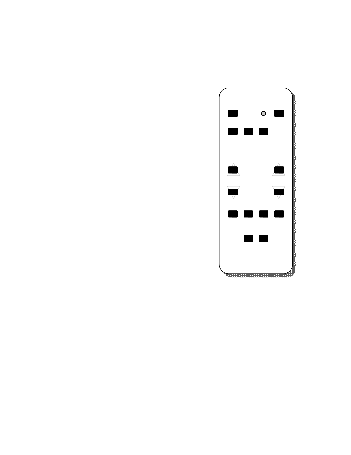
IR Remote Control
All operation and settings are accomplished by means of the Remote Control. The SELENA dedicated Remote Control is
recommended, however most RCA TV compatible remotes will function properly. Use the reference list and drawing below to
determine the function of the keys used to operate the clock.
List of REMOTE CONTROL keys
SELENA Remote key RCA Remote key
MUTE MUTE
TALK POWER
CLK TV
AP1 CABLE
AP2 VCR
UP VOLUME UP
DN VOLUME DOWN
NXT CHANNEL UP
FUN CHANNEL DOWN
SET REW
STRT PLAY
SCAN FF
CLR REC
STOP STOP
HOLD PAUSE
REMOTE CONTROL KEYS description
MUTE 1. Activates the Programming Mode by pressing the MUTE key 5 times within appx. 3 seconds.
2. MUTE internal Alarm Buzzer.
TALK Initiate spoken announcement ( optional )
CLK Press it before operating other keys to put the Remote in the clock communication mode.
AP1 Appliance Type 1 remote operation mode
(not used in regular clock operation)
AP2 Appliance Type 2 remote operation mode
(not used in regular clock operation)
UP 1. Increments the count during data preset in clock, timer/counter or temperature presets modes.
2. In the Function Selection Mode increments the number of the Function selected for (de)activation.
3. In the Normal Operation Mode displays MAX TEMPERATURE MEMORY content.
DN 1. Decrements the count during data preset in clock, timer/counter or temperature presets modes.
2. In the Function Selection Mode, decrements the number of the Function selected for (de)activation.
3. In the Normal Operation Mode displays MIN TEMPERATURE MEMORY content.
MUTE TALK
CLK AP1 AP2
FUN
NXTUP
DN
SELECTCOUNT
CLR
STOP HOLD
SET STRT SCAN
P
R
O
G

6
SELECT NXT 1. After invoking the remote programming mode (by pressing the MUTE 5 times), ACTIVATES
Clock/Temperature data preset mode.
2. During data preset, MOVES the cursor to the next position.
3. During Hi/Lo Temperature Alarm data preset, MOVES to the next alarm data preset.
4. In Function Preset Mode, TOGGLES to Activate/Deactivate selected function.
5. Changes the display brightness when Manual Brightness Control Enabled (Fn 24).
SELECT FUN 1. After invoking the remote programming mode (by pressing the MUTE 5 times), ACTIVATES the
Functions Selection Mode.
2. During the data preset, ADVANCES the screen to the next display function (time, date, temperature
etc...) for preset.
SET INITIATES the PRESET of Timers/Stopwatch/Thermostat or Counter and text in clocks with text display.
STRT STARTS/RESTARTS the Timer/Stopwatch/Counter.
In the Programmable Thermostat mode initiates AUTOmatic control.
SCAN RESUMES the display scrolling ( alternating ) mode during regular operation.
CLR Clears or Resets specific data.
1. RESETS the Temperature to the current temperature reading while MIN/MAX Temperature or
Programmable Thermostat is on display, .
2. RESETS the latch while Hi/Lo Temperature Alarm is pending and Latched Alarm Mode is activated
(will operate only if temperature is outside Alarm range).
3. CLEARS data to 0 in some Counter/Timer preset modes.
STOP HALTS the Timer/Stopwatch/Counter operation.
In the Programmable Thermostat mode initiates MANUal control.
HOLD 1. HALTS the display scrolling ( alternating ) mode at the current display during regular operation.
2. SAVES the preset data into memory for the programmable event Timers and Thermostat.
NOTE, that many keys may be operating only in certain conditions of the display or functions selected. Some keys may not be
active depending upon the model and installed options.
FUNCTION SETUP Procedure
If other programming was performed previously, wait at least 10 seconds for the time-out of the previous mode.
All clock Functions and Options ( See “LIST OF FUNCTIONS” ) can be enabled or disabled by selecting them within the
Function Preset Mode. If not in the Programming Mode already, remember to first initiate the Programming mode by pressing
the MUTE key 5 times within appx. 3 seconds.
Always before using the Remote Control, remember to press the CLK key on the remote to set it to the clock mode.
1. To initiate Function Preset Mode press the FUN key.
2. Using the UP or DN keys select the Function ID Number to be (de)activated ( See “LIST OF FUNCTIONS” ).
3. Enable/Disable the selected function by pressing the NXT key until a DOT in the lower-right corner of the display
comes ON/OFF. When the DOT is OFF, the Function is disabled.
4. Wait for several seconds without pressing any keys. The clock will resume regular operation.
NOTE, that some functions may not be available in your particular clock model depending upon the installed options. In such
case any attempt to enable these functions will be ignored by the system.

7
LIST OF FUNCTIONS
In the Function Selection Mode the display of Functions is preceded by text “Fn” followed by the Function ID Number.
FUNCTION
ID NUMBER
Fn 0 INSIDE TEMPERATURE thermometer display with presettable Lo/Hi Alarm and Min/Max Memory.
The Clock may have an internal or external temperature sensor that monitors the local temperature. Also See Fn 27.
Fn 1 OUTSIDE TEMPERATURE thermometer display with presettable Lo/Hi Alarm and Min/Max Memory.
An EXTERNAL temperature sensor can be connected to the screw terminal accessible on the back panel of the
clock’s enclosure. The sensor may be located up to several hundred feet (meters) away from the clock by extending
its wiring with any type of a 2-conductor cable.
Fn 2 MONTH:YEAR.WEEKDAY display ( 7 segments )
Fn 3 HOURS:MINUTES.SECONDS display ( 7 segments )
Fn 4 HOURS:MINUTES.WEEKDAY display ( 7 segments )
Fn 5 DATE:WEEKDAY.MONTH display ( 7 segments )
Fn 6 DATE:MONTH.YEAR display ( 7 segments ). Also used to display JULIAN DAY when Fn 44 is enabled.
Fn 7 HOURS:MINUTES.SECONDS Presettable Timer/Stopwatch or Up/Down Event Counter Display when selected.
Start, Stop and Reset of the Timer or Counter is accomplished by operating Remote Control keys or optional
External Inputs Terminals hardware ( see Fn 36 ).
Fn 8 12 HOUR time display format.
When this function is not enabled, the default format is 24 hour. In the 6-digits clocks, when this function is enabled,
the “seconds” display may be set to show text “AM/PM” if the function Fn 84 is also enabled.
Fn 9 6-DIGITS display format.
This function is available only when 6-digit display is installed.
Fn 10 INVERTED display MODE (used for 4 digits displays ).
This function causes the display to be inverted 180 degrees so that the clock can be rotated upside-down.
Fn 11 Enable for Preset of Sync Frequency for Power Line Carrier sync. Also used for Protocol Format Selection bit 0 for
ASCII Time Code or Protocol Selection bit 0 for Minute Impulse sync mode
This function is also used when clock is configured for operation in Master/Slave System Clock Network ( see
section “MASTER/SLAVE SYSTEM CLOCK NETWORK” ).
Fn 12 Enable for Colon Blinking when sync detected for Power Line Carrier sync. Also used for Protocol Format Selection
bit 1 for ASCII Time Code (also see Fn 11) or Protocol Selection bit 1 for Minute Impulse sync mode.
Fn 13 Enable to select Hard Wired sync signal for systems similar to Power Line Carrier Sync but without frequency. Also
used for Protocol Format Selection bit 2 for ASCII Time Code or Protocol Selection bit 2 for Minute Impulse sync
mode (also see Fn 11 and Fn 12).
Fn 14 24 HOUR SYSTEM SYNC mode.
This function is used when clock is configured for operation as a slave in Master/Slave System Clock Network.
When function is not selected, default is 12 hour sync mode.
Fn 15 CELSIUS or FAHRENHEIT units selection for all temperature displays.
Fn 16 CONTROL RELAY LATCHING enable during LO/HI Temperature Alarm and Timer/Counter Alarm.
When this function is enabled, the relay will remain latched in OFF state when Alarm is detected even after
temperature returns to normal. To reset the latched state back to ON, press CLR key (twice) on the remote, while
temperature is within NON-ALARM range.
Fn 17 ALARM BUZZER enable during LO/HI Temperature Alarm and Timer/Counter ALARMS.
NOTE that when Wake-Up Alarm is set by disabling Fn 39, the Alarm Buzzer is always enabled.
Fn 18 LOW/HIGH Temperature and Timer ALARM Relay Action.
1. In Low/High Temperature Alarm mode:
When set, this function enables the internal relay to be switched OFF when the Temperature ALARM occurs and

8
ON when there is NO ALARM condition.
When this function is NOT SELECTED the internal relay will ONLY be switched OFF in response to the HIGH
Temperature or Timer ALARM and ON when the Temperature is LOWER than the PRESET for HIGH ALARM
even if it is lower than the preset LOW ALARM.
2. In Timer/Stopwatch Alarm mode:
When set, this function enables internal relay to be switched OFF when the Timer is NOT Active or when the Timer
ALARM occurs (count-down finished). Internal relay will be switched ON when the counting is pending.
When this function is NOT SELECTED the internal relay will ONLY be switched ON when the Timer ALARM occurs
(counting finished),
Fn 19 Temperature display with Decimal Point.
Fn 20 MIN/MAX Temperature Memory display Enable.
Fn 21 BCD Time Code Slave receiver Enable. (compatible with Simplex BCD code for 50Hz and 60Hz line)
Fn 22 POWER LINE FREQUENCY BASED AUTO-CORRECTION Enable. Adjusts automatically to 50/60Hz line.
Fn 23 POWER LINE CARRIER SYNC Enable. Requires the Master clock signal presence in the power line.
( Also see Fn 11,12,13,14 )
Fn 24 MANUAL BRIGHTNESS CONTROL Enable.
When set, this function allows for manual control of the display brightness by activating the “NXT” key. Once set, the
brightness level will be memorized even if this function is subsequently disabled.
Fn 25 AUTO-DIMMING BRIGHTNESS CONTROL Enable (optional ).
Fn 26 INVERTED SECONDS display for 6 digits model.
Fn 27 INTERNAL TEMPERATURE PROBE selection for operation in Thermostat modes and Temperature Min/Max
memory functions. If not enabled, the EXTERNAL sensor is used.
Fn 28 LOOPING TIMER ENABLE. For both UP and DOWN counting the timer/counter will reset and restart itself
automatically upon reaching the PRESET value.
Fn 29 Hi/Lo Temperature Alarm Display Enable.
Fn 30 Hi/Lo Temperature Control and Alarm Mode Enable.
Fn 31 EVENT UP/DOWN COUNTER mode selection. (Function Fn 39 must also be enabled)
When selected, this function enables the Counter of Pulses presented at the COUNTER INPUT terminal if the
External Counter/Timer Inputs are enabled (by Fn 36) or “Clocked“ by the remote control UP and DOWN buttons if
the external inputs are not enabled.
Counter Result (count) display is enabled by Fn 7.
The Counter operates as UP-COUNTER when the preset count is equal 000000 or as UP and DOWN-COUNTER
when the preset is different than 000000 but will not allow for clocking down from count 000000.
NOTE that in the EVENT COUNTER mode the range is 9999 if 6-digit display format is not selected (see Fn 9 ).
Fn 32 2-WIRE (RS232/485) MASTER CLOCK Mode for synchronized system. (also see Fn 46,53,54,55,59 )
When enabled, this mode will cause the clock to function as a Synchronized System Master Clock.
See also functions Fn 33 and Fn 34 .
NOTE: This mode may only be used when the External Communication is installed. A 2-conductor (twisted pair)
cable or another sync configuration should be connected in a network with a Master Clock present and setup as a
transmitter.
Fn 33 2-WIRE (RS232/485) SLAVE clock Mode in DISPLAY REPEAT synchronized system.
All display data will be copied as sent from Active Master clock display in real time. Time data will not be updated in
Slave clock unless Function Fn 34 is also enabled.
Only the clock Preset/Programming mode can override this mode.
NOTE: This mode may only be used when the External Communication terminals are installed. A 2-conductor
(twisted pair) cable or another sync configuration should be connected in a network with a Master Clock setup as
transmitter using SELENA Time Sync protocol.
Fn 34 2-WIRE (RS232/485) SLAVE clock Mode in TIME synchronized system. (also see Fn 46)
Only time data will be synchronized in this mode. All other local options and modes may be still selected.
NOTE: This mode may only be used when the External Communication terminals are installed. A 2-conductor
(twisted pair) cable or another sync configuration should be connected in a network with any type of a PC or a

9
Master Clock present as a transmitter.
Fn 35 STOPWATCH in 1/100 resolution Mode.
This option should be used only when External Inputs Terminals are installed (see Fn 36) .
Fn 36 TIMER/COUNTER Control by EXTERNAL Signals or Contacts ( switches ).
When selected, this function enables External Dry Contact to control the Up/Down Timer or Counter operation.
A Dry Contact must be wired to the INPUT terminals. For this function to control Up/Down Timer the TIMER/
STOPWATCH mode (Fn 39) AND for Counter operation the Event Up/Down Counter option (Fn 31) must be
enabled.
Automatic periodic or persistent display of TIMER or COUNTER readings is enabled by selecting Fn 7. Otherwise,
each time the Timer/Counter is Started, Stopped or Reset, the display will switch automatically to that function.
Many configurations of Timers/Counters are possible using this option. Consult the manual text for details. Also see
Fn 28, 35, 79.
Fn 37 TIMER RELAY Control.
When this function is set, the Internal Relay is controlled by Count-Down Timer/Counter and NOT by LOW/HIGH
Temperature Alarm.
Also see description for Fn 18.
Fn 38 MINUTES:SECONDS display resolution in Timer/Stopwatch mode.
Timer/Stopwatch range is 59min:59sec.
When this function is not set, Timer/Stopwatch default display is HOURS:MINUTES .
Fn 39 TIMER/STOPWATCH mode. (not daily/weekly timers) (See also Fn 31 for Event Counter mode)
When selected, this function enables TIMER/STOPWATCH mode of operation.
Timer operates as UP-TIMER when preset time is equal 0:00.0 (0 hours:0 minutes.0 seconds) or as DOWN-TIMER
when preset is different than 0:00 unless Fn 79 is set for UP timer with a preset limit. Also see Fn 28.
When the function Fn 39 is NOT ENABLED the default is WAKE-UP ALARM Timer mode. It operates then in
HOURS:MINUTES format and allows for presetting of ONE Alarm Time to be repeated every day.
See also Fn 38 and Fn 37.
Fn 40 ALTERNATING DISPLAY SEQUENCE EQUAL SPLIT.
When selected, this function will set equal display persistence periods for each of possible seven display modes as
setup by enabling any combination of functions Fn 0 to Fn 7.
Fn 41 SET TEMPERATURE DISPLAY PERSISTENCE LONGER THAN the CURRENT TIME DISPLAY.
When selected, this function will make the External Temperature (see Fn 1) to be displayed longer than the Current
Time Display (see Fn 3).
Each of possible seven display modes is setup by enabling any combination of functions Fn 0 to Fn 7.
Fn 42 ENABLES automatic HALT of UP/DOWN Timer during Power Failure ( optional ).
This option can be used only if the function Fn 42 is installed and Enabled.
When AC Power Line fails, the Up/Down Timer will recover in HALT mode after power returns. In effect, the timer
will lose the time elapsed during the power failure but the last valid count will be restored.
Fn 43 ENABLES automatic RECOVERY of UP/DOWN Timer after Power Failure ( optional ).
When AC Power Line fails, the Up/Down Timer will recover after power returns without loss of elapsed time and will
continue counting in a mode as operating before power failed.
Fn 44 JULIAN DAY mode selection for display enabled by Fn 6 ( optional ).
For 4 digit displays the format is: “dDDD” where “DDD” is Julian Day reading from 1 to 365 (366 for leap years).
For 6 digit displays, 2 youngest digits will indicate the current year.
Fn 45 MILITARY TIME FORMAT with leading zeroes.
Fn 46 ASCII Time Code protocol selection for Master-Slave communication. Please also see description for Fn 32, 33, 34,
11, 12 and 13.
Fn 47 Minute Impulse synchronization mode. See also Fn11 and Fn12 for protocol selection.
Fn 48 WEEKLY PROGRAMMABLE TIMER, 32 EVENTS PER DAY FOR 7 DAYS repeated each week.
When selected, this function will enable the programming and operation of up to 32 events/day for each day of
week separately. The timer will control internal Alarm Buzzer and Relay as enabled by functions Fn 17 and Fn 37.
Fn 49 TIMER / COUNTER End-of-Count Alarm ( Buzzer or Relay ) persistence limited to 3 seconds.
Fn 50 MULTI-ZONE Master Enable ( synch transmitted once per minute for all zone slaves)

10
Fn 51 MULTI-ZONE Slave Enable ( slaves synchronized once per minute to the signal from the master )
Fn 52 WEEKLY PROGRAMMABLE THERMOSTAT,
HEAT/COOL with AUTO SWITCH-OVER,
32 EVENTS PER DAY separate for each of 7 DAYS, repeated each week.
When selected, this function will enable the programming and operation of up to 32 events/day for each day of
week separately. The thermostat will control up to 2 internal relays; one for Heating and the other for Air-
Conditioning control, or 1 relay for either Heating or Cooling ( A.C. ).
Fn 53 MASTER-SLAVE SYNC SIGNAL RANGE EXTENDER-REPEATER function. See description in the manual.
Fn 54 Time Slot Channel selection bit 0 for RANGE EXTENDER ( see Fn 53 ).
Fn 55 Time Slot Channel selection bit 1 for RANGE EXTENDER ( see Fn 53 ).
Fn 56 RESERVED FOR SYSTEM CONFIGURATION , AFFECTS THE SECONDS DISPLAY ( DO NOT ALTER )
Fn 57 STOPWATCH AS PERIOD TIMER with automatic restart of UP TIMER when the External Start input is activated.
NOTE that this option will work ONLY when the EXTERNAL TIMER INPUTS are installed and enabled by Fn 36.
The display will show only steady reading of the last test and is updated each time the START input is activated.
Fn 58 External STOP input works like HALT in the STOPWATCH TIMER mode. The timer will be “HALTed” only and can
be resumed by reactivating the START input. This feature may be used as a TIMER ENABLE input. NOTE, that this
option will work ONLY when the EXTERNAL TIMER INPUTS are installed and enabled by Fn 36.
Fn 59 300 BPS Communication speed selection for RS232 and RS485 . (If not selected then 9,600 BPS is used)
Fn 60 DAYLIGHT SAVING AUTOCHANGE ( CANADA, USA and MEXICO )
Fn 61 RESERVED FOR SYSTEM CONFIGURATION. CONTROLS ANALOG TEST LIKE TEMPERATURE AND
AUTODIMMING ( DO NOT ALTER ).
Fn 62 TOTAL DISABLE of REMOTE CONTROL.
(TOTAL Lock-out)
All subsequent COMMUNICATION with clock via the Remote Control may be disabled by enabling this function (to
prevent unauthorized operation).
Fn 63 PARTIAL DISABLE of REMOTE CONTROL.
(PARTIAL Lock-out)
All subsequent PRESETS of CLOCK TIME and FUNCTIONS via the Remote Control may be disabled by enabling
this function (to prevent future tampering with the presets).
Other communication like Timers and dimming will still remain accessible.
To regain the control via the remote, the supply power has to be removed for a few seconds or an optional hardware keypad
must be activated at least once. The clock will then respond to the remote control for appx. 33 seconds allowing for the
removal of this Lock-Out if necessary.
Fn 64 DATE / TEXT display mode selection bit 0 ( see Fn 85 )
Fn 65 DATE / TEXT display mode selection bit 1 ( see Fn 85 )
Fn 66 DATE / TEXT display mode selection bit 2 ( see Fn 85 )
Fn 67 to Fn 71 RESERVED
Fn 72 to Fn 74 TIMERS in the TEXT display section ( see Fn 85 )
Fn 75 to Fn 77 TEMPERATURE in the TEXT display section ( see Fn 85 )
Fn 78 JULIAN DAY in the TEXT display section ( see Fn 85 )
Fn 79 REAL TIME CLOCK in the TEXT display section ( see Fn 85 )
Fn 80 TIME ZONE / Customer TEXT DISPLAY ( see Fn 86 )
Fn 81 to Fn 83 RESERVED
Fn 84 AM/PM text indicator enable for 12 hour format of clock time display in 6-digits clocks ( see Fn 8 )

11
Fn 85 DATE / TEXT , ZONE TEXT and other text formats display ENABLE
Fn 86 TIME ZONE / Customer TEXT DISPLAY preset ENABLE ( see Fn 80 )
Fn 87 UP Timer/Stopwatch with a PRESET value. When enabled, will cause the timer to count up from 00:00:00 and stop
at the preset value. Alarm relay and/or buzzer activation at the end of the count-up is possible ( see Fn 16,17,18 and
Fn37 ). Cycling (looping) timer mode is also available ( see Fn 28 ).
Fn 88 to Fn 95 RESERVED

12
CLOCK SETUP
After the clock has been powered down for longer than 2 weeks the time keeping system may have to be preset to the current
time and date.
NOTE:
If a 10 Year Lithium Battery Backup option is installed, the clock will preserve the correct timekeeping for up to appx.
10 year period.
Such battery should be replaced at least once every 10 years, even if no power down occurred.
If a Battery-Less option is installed, each power down period may last up to at least 14 days. It will recharge itself
automatically within several minutes when power is restored.
INITIATING REMOTE CONTROL operation
NOTE that the Remote Control may have been locked-out by enabling the function Fn62 or Fn63.
Irrespective of any previous settings, the clock will always accept the Remote Control commands for a period of
appx. 33 seconds following each power up and this period is extended by further 33 seconds whenever a valid key on
the remote is used.
During that initial period the functions Fn62 and/or Fn63 may be disabled to cancel the Remote Control lock-out.
Always before using the Remote Control, remember to press the CLK key to set it to the clock mode.
If the Remote Control is Enabled and the power has been present for longer than appx. 33 seconds, press the MUTE key 5
times within appx. 3 seconds period to initiate the clock PROGRAMMING mode. This mode time-out is extended by further
33 sec. each time a valid key is pressed. If that timer expires, the MUTE button has to be activated again 5 times (within appx.
3 seconds) to restart the programming mode.
TIME / DATE SETUP
After the power-up the clock may display the text: “SEt” if the internal backup ran “out of charge” or the clock was not
previously set. If however the time is still correct, the clock will resume regular operation.
After initiating the clock PROGRAMMING mode as described above, perform the following:
1. Press the NXT key to initiate the Clock Time Preset Mode and with UP and DN keys set the time minutes and hours.
2. Using the FUN key scroll to the display screen with month and year, and with UP and DN keys set the current data.
3. Using the FUN key scroll to the display screen with date and month, and with UP and DN keys set the current date.
4. Using the FUN key scroll to the display screen with day-of-week and with UP and DN keys set the current day.
5. Wait for several seconds without pressing any keys. The clock will resume regular operation.
NOTE: During programming use the “NXT” key to move the cursor when needed.
NOTE, that the clock Seconds are RESET to 00 each time a preset of the clock time minutes is
performed or the “CLR” key is pressed during the real time clock preset.
DISPLAY MODE SETUP
Several Clock Display modes can be enabled/disabled by enabling/disabling the corresponding Functions: Fn 0 to Fn 7. Go to
the Function Preset Mode ( See “LIST OF FUNCTIONS” ) by following the steps listed in “FUNCTION SETUP Procedure”.
When more than one display mode is enabled the clock will display these screens in an ALTERNATING fashion. For example:
if Fn 3, Fn 2 and Fn 1 are enabled, the display will start with HOURS:MINUTES display followed by MONTH:YEAR display,
followed by EXTERNAL TEMPERATURE display and all over again: HOURS:MINUTES display followed by ... etc...etc...
NOTE, that the Real Time Clock mode (Fn 3), when alternating with other displays, always persists on the display the longest
(appx. 15 sec) while other displays will each remain on for shorter periods (appx 4 sec). This persistence split may be altered
by enabling the functions Fn 40 and / or Fn 41 .
If only one display mode is enabled, it will remain on the display all the time.

13
All three Time Formats are available on all SELENA clocks.
Function Fn 8 can be used to select between the 12 and 24 hour format.
To select the Military Time format, enable the function Fn 45.
To select the display of AM or PM text indicator in the 6-digit clock,
enable the functions Fn 8 and Fn 85.
HALTING the ALTERNATING DISPLAY
User may (ON DEMAND) HALT the alternating display by pressing the HOLD key at any time. The format currently on display
will remain active until either a programming mode is initiated or a SCAN key is depressed. Similarly, whenever the Timer/
Counter START, STOP or RESET is performed externally via the remote, the display will switch to the timer/counter mode.
Press the SCAN key to return to other displays.
NOTE: when the function Fn 62 is enabled, ALL COMMUNICATION with the clock via the remote control is DISABLED. To
regain the remote control access remove the power momentarily and disable Fn 62 within 33 seconds.
( Also see Function Fn 63 ).
DATE / TEXT and ZONE Text display ( Optional Feature )
This TEXT option may be activated by enabling the Function Fn 85.
In clocks with the optional Alpha Numeric text display installed, several modes for displaying of the current date and other text
modes may be selected by enabling the functions as per the table below:
Fn64 Fn65 Fn66
Mode “0” 0 0 0 no date display
Mode “1” 1 0 0 FRI-OCT-12
Mode “2” 0 1 0 OCT-12-FRI
Mode “3” 1 1 0 12-OCT-FRI
Mode “4” 0 0 1 FRI-12-OCT
Mode “5” 1 0 1 12-OCT-2007
Mode “6” 0 1 1 OCT-12-2007
Mode “7” 1 1 1 2007-12-OCT
Mode “8” Fn 72 HH-MM-SS ( timer or counter ) ( also see Fn 35,38,39, )
Mode “9” Fn 73 TIMER MM-SS ( timer ) ( also see Fn 35,38,39, )
Mode “10” Fn 74 DDD-HH-MM ( timer or counter ) ( also see Fn 35,38,39, )
Mode “11” Fn 75 IN 25 C ( or 77 F ) ( also see Fn 0 and Fn 1 )
Mode “12” Fn 76 OUT 25 C ( or 77 F ) ( also see Fn 0 and Fn 1 )
Mode “13” Fn 77 TEMP 25 C ( or 77 F ) ( also see Fn 0 and Fn 1 )
Mode “14” Fn 78 DAY 245 ( Julian day of the year )
Mode “15” Fn 79 HH-MM-SS AM/PM ( real time clock ) ( also see Fn 8, 45, 84 )
Mode “16” Fn 80 TIME ZONE / Customer TEXT DISPLAY ( also see Fn 86 )
NOTE 1: If the Functions Fn 64,65,66 are set to 000, the Date Text will not be displayed. However the other text modes may
still be activated and will display in an alternating manner if more than one is enabled.
NOTE 2: In order to make any Text display alternate with the current Date Text, enable one of the Modes “1” to “7” and
ALSO enable any number of the other Functions listed above.
NOTE 3: The alternating text display can be “halted” at any time by pressing the HOLD key. The alternating display can
then be subsequently resumed by pressing the SCAN key at any time.
NOTE 4: The alternating text display is “halted” automatically whenever any of the clock programming modes is initiated.
To resume the alternating display press the SCAN key at any time.
IMPORTANT ! Some TEXT modes may NOT be available in some clock models.
ZONE TEXT Setup
SELENA clocks equipped with the alphanumeric TEXT display option can display any custom programmed text, for instance
the time ZONE name. The text is stored in a permanent memory and will remain there until changed, even without power.
To Enable the ZONE TEXT PRESET mode, enable the function Fn 86.

14
NOTE, that the clock programming mode DOES NOT HAVE TO BE ACTIVATED to program the ZONE TEXT.
1. Press the SET key to initiate the ZONE TEXT Preset Mode.
The left-most character in the Text display section will begin to flash.
NOTE, that if the character has been previously set as “ “ ( space) it may not show as flashing. Continue to the next
step.
2. Press the UP or DN key to preset the character.
Use the NXT key to move the flashing cursor to the next position.
3. When finished programming of all characters, press the MUTE key to store the entire text in the internal memory.
4. To DISABLE the text preset mode, disable the function Fn 86.
When this function is disabled, the SET key will not activate the text preset mode, but can be used normally for all
other timer/counter modes.
WAKE -UP ALARM CLOCK Setup
SELENA can be set to function as an Alarm Clock and perform presettable Wake-up Alarm each day until disabled.
To enable the WAKE-UP ALARM mode, make sure that the functions Fn 39, 31 and all other Timer/Counter and Thermostat
modes are DISABLED.
In this mode only HOURS:MINUTES can be set and during the preset the display will always operate in the 24-hour format.
NOTE that the programming mode DOES NOT HAVE TO BE ACTIVATED to preset the Wake-Up Alarm which may be
performed at any time during the normal clock operation (if Stopwatch or other programmable timers are Not Enabled).
1. Press the SET key to initiate WAKE-UP ALARM Preset Mode.
2. Using the UP and DN keys preset the Alarm HOURS and MINUTES.
Use the NXT key to move from minutes to hours and back.
NOTE. To reset the time to 0:00 press the CLR key.
3. When finished, wait for several seconds without pressing any keys. The clock will resume normal operation and a
DOT in the lower-right corner of the display will begin flashing. This is an indication that Alarm is preset and active.
NOTE that the Wake-Up Alarm may be activated at any time during the normal clock operation by pressing the SET key.
If the preset Alarm Time is satisfactory, wait for few seconds for the display to return to regular operation. Slow flashing of the
lower-right decimal point will indicate that the alarm is activated.
TO CANCEL the Wake-Up Alarm, press the STOP key at any time during the normal clock operation. The lower-right decimal
point will switched off in response.
IMPORTANT.
Whenever the function Fn 39 is enabled, the WAKE-UP ALARM will be automatically deactivated until Fn 39 is disabled
again. However, the Wake-Up Alarm preset time will remain unchanged in the memory.
TO SILENCE the Wake-Up Alarm, press the MUTE key at any time while the alarm buzzer is sounding. The Buzzer will be
silenced and the Alarm deactivated.
In order to reactivate the alarm for the next day, press the SET key as described previously.
The Soft Wake-Up Alarm Buzzer feature controls the buzzer sound to come on less frequently at the beginning and becomes
more frequent as the alarm continues. This makes the wake-up alarm buzzer less annoying.
The Wake-Up Alarm Buzzer active period is limited to 4 minutes unless silenced or cancelled sooner.

15
UP/DOWN STOPWATCH TIMER and EVENT COUNTER
SELENA can be used to function as a presettable UP/DOWN STOPWATCH TIMER AND EVENT COUNTER with an Alarm
Buzzer and Internal Relay Control.
To enable the UP/DOWN STOPWATCH TIMER mode, make sure that the function Fn 39 is ENABLED. For the Up/Down
Event Counter mode, the function Fn 31 MUST also be enabled.
There are two possible timer formats:
1. MINUTES:SECONDS format when function Fn 38 is enabled.
2. HOURS:MINUTES format when function Fn 38 is disabled.
NOTE that in the 6-digit display models the SECONDS are also operational.
NOTE, that the programming mode DOES NOT HAVE TO BE ACTIVATED to preset the Up/Down Timer/Counter, which may
be performed at any time during the regular clock operation.
ATTENTION: In ALL TIMER MODES with 4-digit display and when the MINUTES:SECONDS display format (Fn 38) is
NOT SELECTED, the following will occur:
During the FIRST hour of the count UP or the LAST hour of the timer count Down, the display of Hours:Minutes will switch to
Minutes:Seconds to allow the user to monitor the time with better accuracy.
To Preset the COUNT UP/DOWN STOPWATCH TIMER or EVENT COUNTER:
NOTE: If the function Fn87 is NOT ENABLED, the Count-Down operation of the Timer is selected by presetting the START
TIME as different than 00:00(.00). Otherwise it will function as a Count-Up Timer. The Event counter can count Up or Down
independent of the preset but will not go DOWN past the 000000 count ( unless the function Fn28 for “looping” timer is
enabled ).
1. Press the SET key to initiate UP/DOWN TIMER/COUNTER Preset Mode.
NOTE, that the display will automatically switch to the Timer/Counter Mode and will show the last preset.
2. Using the UP and -DN keys preset Timer HOURS and MINUTES (or Counter Initial count) or leave it unchanged.
Use the NXT key to move from minutes to hours or seconds (or count digits) and back if necessary.
NOTE: To reset the time/count to 00:00 (:00) press CLR key.
3. When finished, wait for several seconds without pressing any keys. The clock will resume the normal operation.
To START the COUNT-DOWN STOPWATCH TIMER or COUNTER:
NOTE: When the TIMER PRESET is different than 00:00(.00) and the Fn87 is Disabled, the timer will operate in the
COUNT-DOWN mode.
1. Press STRT key at any time during normal clock operation. In the Event Counter mode, press DN key.
2. The previously preset start time/count will be automatically loaded in and the Timer will begin the Count Down.
3. To HALT the timer press STOP key. The count-down will be halted (suspended). No effect in Event Counter mode.
4. To Resume the timer press STRT key. The count-down will be resumed. No effect in Event Counter mode.
5. When the Time or the Count 00:00.00 is reached, the timer will stop. Alarm Buzzer (if enabled by Fn 17) will sound
and the Alarm Relay will operate (as selected by functions Fn 18 and Fn 37).
6. To RESET the Timer/Counter at any time press SET key. To reset the relay in the Counter mode the CLR key may
also be used.
NOTE:
The clock DOES NOT have to remain in the Timer Display mode to continue the Up/Down Timer operation. During the Count-
Down a DOT in the lower-right corner of the display will be rapidly flashing if the display is in the Real Time Display mode.
If it is in the Timer Display mode, the Colon Dots will flash rapidly instead. This is an indication that the TIMER is operating.
In the HALT timer mode the colon will flash rapidly pausing every several seconds.
NOTE: In the Counter mode the colon is extinguished.

16
To START the COUNT-UP STOPWATCH TIMER or COUNTER with 00:00 preset:
NOTE: When Fn 87 is NOT enabled and the TIMER PRESET is 00:00(.00), the Timer will operate in the COUNT-UP
mode.
1. Press STRT key at any time during normal clock operation. In the Event Counter mode, press the UP key.
2. The preset 00:00.00 time will be automatically loaded in and the Timer will begin the Count Up.
3. To HALT the timer press STOP key. The count-up will be halted (suspended). No effect in Event Counter mode.
4. To Resume the timer press STRT key. The count-up will be resumed. No effect in Event Counter mode.
5. To RESET the Timer/Counter at any time press SET key.
To START the COUNT-UP STOPWATCH TIMER or COUNTER with ANY preset:
NOTE: When Fn 87 is enabled, the TIMER may be PRESET to ANY value within the timer range. the Timer will operate in
the COUNT-UP mode and will stop at the preset value. Each time the START is activated, the timer will jump to 00:00 and
continue counting up to the preset value.
To set up this timer, follow the procedure for operation of the Count-Down timer/counter.
NOTE:
1. The Alarm Buzzer and the Internal Relay can be controlled by the Timer while in the Count-Up mode only if Fn 17 is
also enabled. Also see Function Fn 49 for how to set short time Buzzer or Relay ON period.
2. The clock DOES NOT have to remain in the Timer Display mode to continue the Up/Down Timer operation.
During counting a DOT in the lower-right corner of the display will be rapidly flashing if the display is in the Real Time
Display mode.
If it is in the Timer Display mode, the Colon Dots will flash rapidly instead.
This is an indication that the TIMER is operating. In the HALT mode the colon will flash rapidly pausing every several seconds.
Note, that when the clock is a part of a synchronized Master-Slave network, the flashing colon or flashing dot feature for timers
may not function the same way.
CYCLING ( LOOPING ) UP/DOWN STOPWATCH TIMER ( automatic Reset and Restart )
This function may be used either with the remote control or when the external inputs for Start, Stop, Reset are installed (see
Fn36 ).
By enabling the function Fn 28, the timer may be set to the LOOPING mode of operation. In this mode, once STARTed, the
timer/stopwatch will continue counting down ( or UP if function Fn 87 is also enabled ), until it reaches 00:00 in the count-down
mode or the PRESET value in the count-up mode. At this point it will reset itself to the starting value and continue counting.
This process can be interrupted at any time by activating the STOP or SET ( RESET ) key ( or external input ).
NOTE, that in this mode the internal buzzer and/or relay CAN also be controlled by the timer. See the functions Fn 17, 37, 49.
At each “expiry” of the timer, the internal buzzer ( Fn17 ) and/or the internal relay ( Fn37 ) may be enabled to become active
for a short period ( 3 to 5 seconds when Fn49 is also enabled ) or until the MUTE or the SET button is pressed on the remote
( or until the external RESET input is activated ).
Please note, that when the remote control is used to operate the timer or when Fn 58 is enabled and the external START/
STOP/RESET inputs are used, the timer can be “HALTed” at any point and then restarted.
UP / DOWN TIMER RECOVERY after the Power Failure ( Optional Feature )
When the function Fn 43 is Enabled, the Up/Down timer can recover the lost time and continue counting as if the power was
present all the time.
When the function Fn 42 is also Enabled, the lost time will not be taken into account and the timer will restart in the HALT
mode after the power returns. To continue counting, press START key on the remote ( or activate the external START input ).
This option may not be available on standard clock models unless specifically ordered.
1/100 SECOND RESOLUTION for UP TIMER/STOPWATCH ( Optional Feature )
This function may be used only when the external inputs for Start, Stop, Reset are installed.
Enable the function Fn 36 and Fn 35. Note, that this option can only be used in 6 digit displays to show Min:Sec:1/100 sec.

17
AUTORESTART for UP TIMER / STOPWATCH ( Optional Feature )
This function may be used only when the external inputs for Start, Stop, Reset are installed ( Optional Feature ).
Enable the functions Fn 36 and Fn 57.
NOTE: The 1/100 second resolution mode may also be activated by enabling the function Fn 35 if the display has 6 digits.
In the Autorestart mode, the timer will start counting UP when the START input is activated and will automatically STOP and
RESTART each time the START input is reactivated. At each RESTART, the display will show the “most recent count”
between the two starts. Activating the STOP input will stop the timer permanently until the START input is activated again.
The Autorestart mode can be used to “measure” the time periods between periodically occurring events ( the START input
activations ).
18
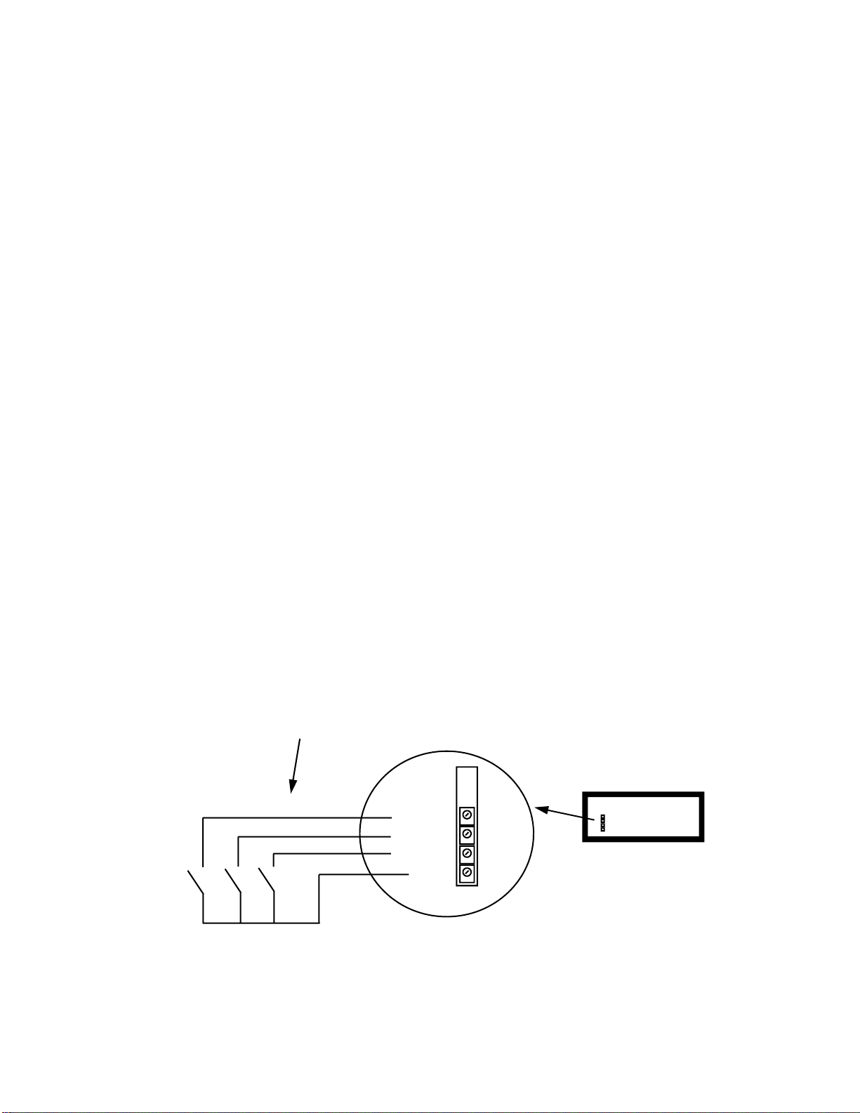
EXTERNAL START/STOP/RESET INPUTS FOR UP/DOWN TIMER/STOPWATCH
and EVENT COUNTER ( Optional Feature )
The SELENA timers and event counters may be set up to use external inputs for Start, Stop (count UP, count Down) and
Reset. These inputs are available via the screw terminal block accessible at the back panel ( if installed ).
To activate the External Inputs for the Up/Down Timer/Stopwatch or Event Counter, enable the function Fn 36.
CAUTION: External inputs may be connected to DRY CONTACTS ONLY. Any voltage carrying signals connected to those
inputs may cause irreversible damage. However, in special applications it is possible to apply a voltage within the range from
0 to +5V between the Common (0V) and any of the external control inputs if an external current limiting resistor is also used.
The Timer activated via the external inputs behaves in a similar fashion as when it is operated using the Remote Control unit.
However, note the following:
1. The Timer or Counter initial count may be preset only via the remote control (after pressing the SET key).
2. A) If the Function Fn58 is NOT ENABLED, activating the START input will start the timer only if it was previously
RESET either by activating the external RESET input, or via the remote control, by pressing the SET key.
In the Event Counter mode (Fn31), the count will be incremented by 1.
B) If the Function Fn58 is ENABLED, activating the START input will start or restart the timer only if the STOP
(HALT) input is NOT activated.
In the Event Counter mode (Fn31), activating the UP input will increment the count by 1.
3. A) If the Function Fn58 is NOT ENABLED, activating the STOP input will stop the timer and it may only be
restarted from the beginning after activating the RESET input or pressing the SET key on the remote.
B) If the Function Fn58 is ENABLED, activating the STOP (HALT) input will “halt” the timer.
C) If the Function Fn58 is ENABLED, and the START input is permanently activated, then the STOP (HALT)
input may be used as the “DISABLE” for the timer for as long as this input remains activated.
In the Event Counter mode (Fn31), activating the DN input will decrement the count by 1.
NOTE: If the internal buzzer is enabled (Fn17) it will be activated whenever the count reaches 0000 while counting
down. The MUTE key or the SET key on the remote, or external RESET input may also be used to silence the
buzzer ( or reset the internal relay ).
4. If the Function Fn 7 is not set as the exclusive display screen mode, pressing STRT, STOP or SET key on the
remote will bring the Timer display on screen. Similarly, activating the external RESET input will have the same
effect.
5. When the External Inputs are enabled (by enabling the function Fn 36), only the SET key on the remote may
activate the timer or counter preset. The STRT and STOP keys on the remote are not operational in this mode.
Common
RESET
STOP / DN
START / UP
WIRING OF EXTERNAL DRY CONTACT SWITCHES FOR TIMER/COUNTER OPERATION
BLACK
Colors of wires if Cables
supplied with the clock
RED
WHITE
GREEN
START / UP
STOP / DN
RESET

19
Common
RESET
STOP / DN
START / UP
STANDARD OPTION
WIRING OF EXTERNAL DRY CONTACT SWITCHES FOR TIMER/COUNTER OPERATION
WITH THE STOP INPUT OPERATING AS THE TIMER / COUNTER ENABLE / DISABLE
( NORMALLY ENABLED )
OPEN = COUNT ENABLED
CLOSED = COUNT DISABLED
RESET
JUMPER
Common
RESET
STOP / DN
START / UP
SPECIAL OPTION
WIRING OF EXTERNAL DRY CONTACT SWITCHES FOR TIMER/COUNTER OPERATION
WITH THE STOP INPUT OPERATING AS THE TIMER / COUNTER ENABLE / DISABLE
( NORMALLY DISABLED )
CLOSED = COUNT ENABLED
OPEN = COUNT DISABLED
RESET
JUMPER
STOP / DN

20
PROGRAMMABLE MULTI-EVENT TIMER ( Optional Feature )
Programmable event timer modes allow for presetting of time instances (hours and minutes of the day for each day of the
week) at which the internal buzzer and/or relay may be activated in order to control the operation of some external devices
and/or sounding an Alarm.
The duration of each event is also individually programmable. There may be up to 32 events per day and each day of the
week may be programmed with a different schedule.
The programmable multi-event timer may be selected by enabling the function Fn48.
Each event time occurrence and event duration period (alarm period) may be programmed. In addition, each event can be
marked to perform OPTIONAL activation of a COUNT-UP or COUNT-DOWN timer that will run and display until the next
event.
All programmed data is stored in the internal, permanent memory which is retained even without supply power.
MULTI-EVENT TIMER PROGRAMMING
The Multi-Event Timer may be programmed at any time during the regular clock operation and DOES NOT require invoking of
the clock programming mode.
1. Press SET key at any time during normal clock operation.
Display will show the Weekday and the Event number for that day.
2. The Event number will flash rapidly to indicate that it is active for selection. Use UP and DN keys to select the event
number for that day.
3. To move cursor to the Weekdays press NXT key.
Use UP and DN keys to select the day and press NXT key. Display will show: du:xx (or: dxxx)where “xx” (or
“xxx”)is the duration period in seconds for the Alarm event being programmed.
NOTE that when duration is set to 59 seconds, the relay ( or buzzer ) will remain energized (if enabled by function
Fn37) until the next occurring Alarm with the duration programmed as different than 59 seconds.
4. Using UP and DN keys, set the required Alarm duration period in seconds. When satisfied, press NXT key.
5. The display will show the hour and the minute (HH:MM) of the event that day. Using UP and DN keys preset the
required time of the event. To move the cursor press NXT key.
6. The display will show: OP zz , where “zz” is the additional option that can be activated at the time of the event.
Using UP and DN keys preset the required option of the event. The available options are as follows:
Option “00” = no options.
Option “01” = count UP timer to be started automatically and count UP the time until the next event .
Option “02” = count DOWN timer to be started automatically and count DOWN the time until the next event .
7. When satisfied with the preset time and duration, press HOLD key to store the data in memory.
MAKE SURE that this is done WHILE either the duration or the Alarm Hours:Minutes is on display. If it is not
done so, the OLD data shall be restored in the program memory.
8. Display will flash text: “Strd“ momentarily to indicate that the Alarm data has been stored in memory.
9. Press NXT key to go back to Step 2 in order to continue programming of other Alarm events
or
Wait a few seconds for the system to return to the Normal Operating Mode. The Event Timer schedule will be
executed automatically.
NOTE that the order in which the clock is searching for active alarms is from event “00“ thru event “31“. The search is
performed at 00 seconds of each minute of real time. First encountered active alarm shall be executed and further search shall
be aborted until next minute of real time clock reading. Therefore, if more than one event for the day is identical with any
other, only the younger (in order) event number shall be executed. This may have application in deactivating unused alarm
events by setting them as identical to the highest used event number for the day.
To Enable the Internal Relay operation during the Timer Alarm periods, enable the function Fn37 (see FUNCTION
SETUP Procedure section). Also see Function Fn 49 for how to set short time Buzzer or Relay ON period.
To Enable the Internal Buzzer operation during the Timer Alarm periods, enable the function Fn17 (see FUNCTION
SETUP Procedure section). Also see Function Fn 49 for how to set short time Buzzer or Relay ON period.
To SILENCE THE BUZZER ONLY without affecting the RELAY during a pending Alarm, press MUTE key.
To SILENCE THE BUZZER or DEACTIVATE the ALARM RELAY during a pending Alarm, press the SET key and wait a few
Other manuals for SELENA HY-4 Series
1
This manual suits for next models
1
Table of contents
Other Kera Clock manuals


