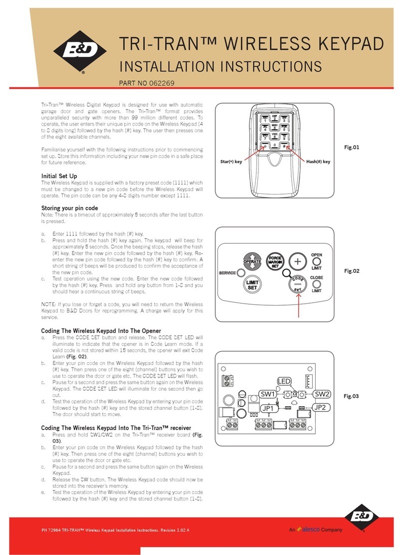
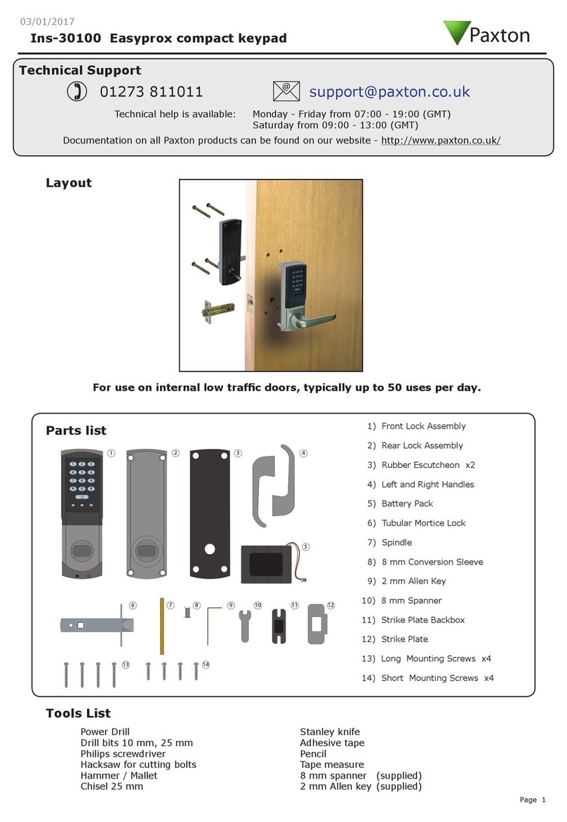
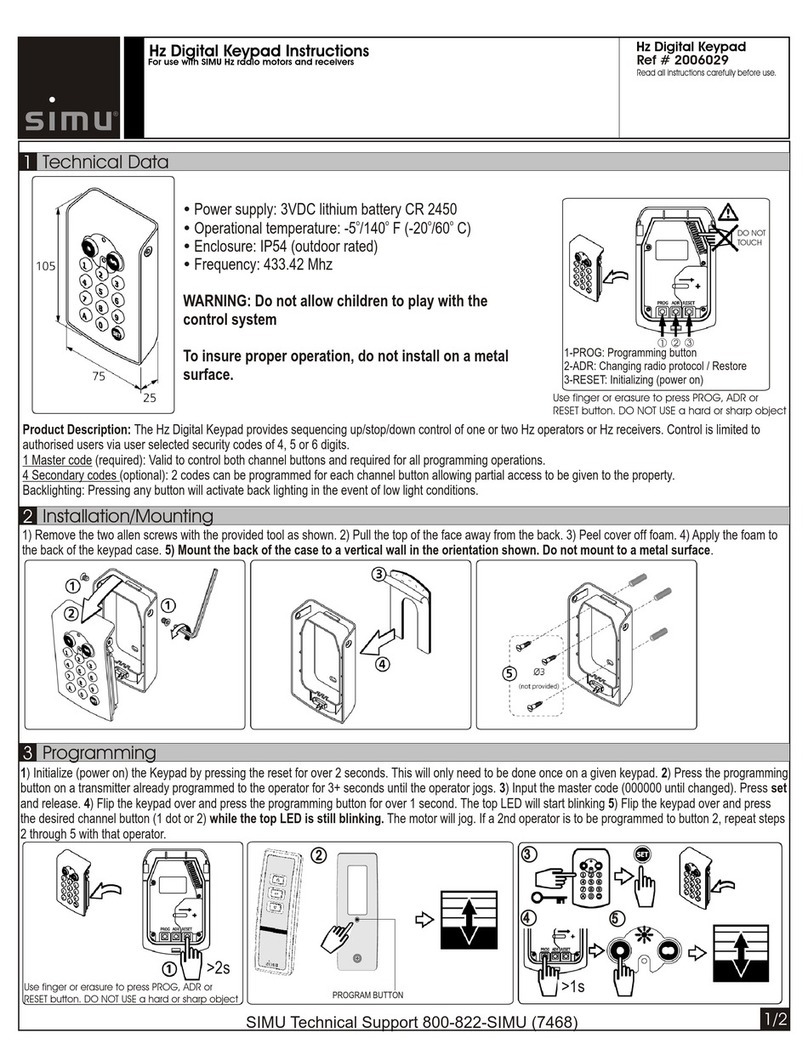
KeriSystems B100-KP User manual

BioSync Fingerprint Readers
- 1 -P/N: 02384-001 - Rev C
B100-KP Fingerprint Reader
Setup Guide

BioSync Fingerprint Readers
- 2 -P/N: 02384-001 - Rev C
Table of Contents
1.0 Introduction 3
2.0 Mounting Instructions 4
3.0 Wiring Instructions 6
4.0 Connecting the B100 Readers to Multiple NXT-MSC Controllers 10
5.0 Add the B100-KP to the BioManager Software 10
6.0 Enrolling Users Using the Reader 14
7.0 Enrolling Fingerprints 16
8.0 Check Communication and Memory Status 17
9.0 Deleting Fingerprints 18
10.0 Changing the B100 Reader Mode 19
11.0 Enable or Disable the Keypad or Sensor Backlight 20
12.0 Enrolling the Users into Doors.NET 21

BioSync Fingerprint Readers
- 3 -P/N: 02384-001 - Rev C
1.0 Introduction
Setting up a B100-KP reader as a new installation is a three step process. Each of these
steps is covered in its own document:
lBioManager Software Installation (p/n: 02301-001)
lCNV Converter Setup (p/n: 02303-001) - (used to connect to the BioSync
via ethernet)
lB-100 KP Reader Setup - (p/n: 02384-001)
Note: The current version of the BioManager software is version 15 (at the time of writ-
ing). You can download the latest version from the Software Downloads section of the
Kerisys website.
This guide explains the process of wiring the B100-KP reader to the controller, con-
necting to the reader for the first time, configuring the reader then enrolling user fin-
gerprints and PINs.

BioSync Fingerprint Readers
- 4 -P/N: 02384-001 - Rev C
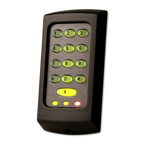
The B100-KP biometric keypad reader is a Wiegand biometric fingerprint reader and
keypad for indoors and outdoors access control applications and features a backlight
and programmable Wiegand output.
It offers storage of up to 100 fingerprints, programmable Wiegand output (8 to 128 bits)
and selectable PIN code length. There is also a tamper switch which is activated if an
attempt is made to open or remove the unit from the wall. You can wire the tamper
switch into an available input (for example, on a 4x4 module) and then set up an aler-
t/sound alert within Doors.NET.
2.0 Mounting Instructions
If the biometric reader is installed and used outdoor, the reader MUST be fitted with the
MCD-MINI metal cover available in our accessories in order to protect the sensor from
direct rainfall. The operating temperature of the product is between -15ºC - + 50ºC. If
the reader is installed in an environment where the temperature can drop below -10ºC
or/and if the sensor could only be exposed to direct sunlight, it is strongly recommended
to install the reader inside a third party sealed wall mount box (fitted with additional
heater if very low temperature) to keep a constant sensor level performance. Keri Sys-
tems™ cannot guarantee the functionality of the product if measures and advice before
are not followed.

BioSync Fingerprint Readers
- 5 -P/N: 02384-001 - Rev C
It is also strongly recommended to use dual technology biometric readers when used out-
doors to offer first higher security but also the possibility to use different readers to suit
different types of users.

BioSync Fingerprint Readers
- 6 -P/N: 02384-001 - Rev C
3.0 Wiring Instructions
3.1 Wiring to an NXT RM3 (Reader Interface Module)
Reader Interface Module Notes:
lOn the Reader Interface Module (RM3) the J3 jumper should be set to pins 1 and 2.
This will provide 12VDC to the B100 reader and when correctly set the D10 LED
should be solid red.
lIf you are using a Wiegand-only module, by default the LED mode will be correctly
set (providing the RM3 is using firmware version 03.03.10)
lIMPORTANT: If you have an NXT 4x4 module connected on the same bus as the
reader, you MUST use a separate power supply to power the reader/keypad.
lThe Reader Interface Module (RM3) is only supported with the NXT and NXT-MSC
controllers.

BioSync Fingerprint Readers
- 7 -P/N: 02384-001 - Rev C
3.2 Wiring to the PXL-500W Controller
PXL Notes:
lOn the PXL-500W controller, the JP5 jumper should be set to pins 1 and 2 - this will
provide 12VDC to the BioSync and on the PXL-500W LED10 will be solid red.
lBioSync readers ar eONLY supported on the PXL-500W, they are NOT supported on
the PXL-500P controller.
lWhen using the PXL-500W controller with BioSync readers, the controller will pro-
cess up to 31 Wiegand bits.
3.3 Wiring to an EP Controller (i.e EP-1502)

BioSync Fingerprint Readers
- 8 -P/N: 02384-001 - Rev C
EP Controller Notes
lBioSync readers have two LED lines but the EP controllers only have one LED pin-
out. This is overcome by wiring the Red LED wire into the buzzer pin-out (pin 4) and
in Doors.NET you have to set the BioSync reader as being a Dual LED reader type.
- In Doors.NET go to Setup >> Hardware Setup >> All.
- Locate and highlight the BioSync reader in the hardware tree.
- Ensure Advanced View is enabled for the reader properties.
- Locate LED/Buzzer.
- Set the reader for Separate Red and Green, No Buzzer.
Note: This will set the controller to use the buzzer for controlling the second LED line and
because of this the reader does not generate any sound when the door is forced or held
open.
lWhen using BioSync readers with EP controllers you have to use custom LED Modes
to define the LED behavior for the various reader modes (i.e - access granted,
access denied, locked, unlocked, lockdown, etc). Setting up and using Custom LED
Modes is covered in a separate section and available as a standalone document
(p/n: 02315-001).

BioSync Fingerprint Readers
- 9 -P/N: 02384-001 - Rev C
General Notes
lThe shield wire connects with the black (Ground) wire at the controller. At the
reader side they are kept separate to prevent a ground loop.
lThe maximum reader cable run distance for the BioSync readers is 150m/500 ft (as
per industry standard specifications).
lTypically the BioSync readers will be powered from the controller so ensure the con-
troller's power supply outputs enough current for the controller and all connected
devices.
lThe maximum current draw for the BioSync B100-KP is approximately 150mA.
lWhen using a separate power supply for the reader, connect the Ground for both
devices to ensure correct transfer of the Wiegand signal.
lWhen you have connected the reader to the controller and applied power, the
B100 LED bar should flash amber and the reader will beep twice.
lWhen the B100 reader is first powered up there will not be a backlight (by default
the backlight is disabled) but can be easily enabled once it is online to the BioMan-
ager software.
lThe BioSync readers are supplied with a 120 ohm resistor. This resistor should be
used to terminate the RS-485 network on large networks/long cable runs if the com-
munication is not stable. The network is terminated at the CNV-1000 convertor
using a jumper across both pins

BioSync Fingerprint Readers
- 10 -P/N: 02384-001 - Rev C
4.0 Connecting the B100 Readers to Multiple NXT-
MSC Controllers
5.0 Add the B100-KP to the BioManager Software
Once you have installed the BioManager Software, setup the CNV converter, set the
reader's DIP switch and added the CNV converter as a portal, you are ready to add the
B100 to the BioManager software.
5.1 Scan for the B100-KP Reader
When using the CNV-1000 converter you can use the scan facility to automatically detect
the BioSync. You will therefore not initially need to find out the device ID/serial number -
this is the quickest and easiest method to add the B100.
Note: There is no maximum number of portals that can be added to the software. A sys-
tem can use any number of CNV-1000 converters.
1. Click the BioManager client desktop icon.

BioSync Fingerprint Readers
- 11 -P/N: 02384-001 - Rev C
2. If using BioManager for the first time you will be automatically logged into the cli-
ent, otherwise you may be prompted for a user name and password.
3. On the left of the screen you should see a portal listed. An existing system will also
have BioSync readers listed.
4. Right-click on the communication portal.
5. Select Search devices.
6. A 15-second timer will begin to count down.
7. The detected B100 reader(s) will show in the search window.
8. Highlight the detected reader then click to Add Reader.
5.2 Manual Add
The manual add option is useful if the hardware has not yet been installed but you want
to begin setting up the system in advance.
1. Open the BioManager software via the client icon on the desktop.
2. Right-click on the Portal which should already be listed and select Add Reader.

BioSync Fingerprint Readers
- 12 -P/N: 02384-001 - Rev C
3. The Add Reader window will appear.
4. Enter a description for the B100.
5. Select the exact model (B100-KP) from the Type drop-down list.
6. Select the Wiegand output type. Typically for the B100-KP this should be left at the
default setting of Wiegand26.
7. The Wiegand Output type should be SingleWiegand.
8. On the reverse of the B100-KP (under the mounting bracket), you will see a white
label which has a wiring diagram and the device ID/serial number - you should
make a note of this number.

BioSync Fingerprint Readers
- 13 -P/N: 02384-001 - Rev C
9. Enter the device ID/serial number.
10. For now, all other settings can be left at their default values.
11. Click the SAVE & EXIT button.
12. In the live events grid you should see an online message for the reader.
13. You are now ready to start adding user PINs and fingerprints.

BioSync Fingerprint Readers
- 14 -P/N: 02384-001 - Rev C
6.0 Enrolling Users Using the Reader
1. Double-click the Users link to open the User window.
2. Click the New User button.
3. Enter a User ID (Cardnumber) - This is the number that will be transmitted by the
B100 to the Doors.NET software - It therefore will be unique to each users.
Note: If users will also be using 26-bit Wiegand cards on the Doors.NET system you
should enter the cardholder's credential Imprint and Facility Code to automatically
create the unique User ID. The Imprint (User Code) and Facility Code (Site Code)
are entered as shown below:

BioSync Fingerprint Readers
- 15 -P/N: 02384-001 - Rev C
4. Next, enter an Access Code (this in the number that is entered into the keypad).
5. Click the SAVE NEW button.

BioSync Fingerprint Readers
- 16 -P/N: 02384-001 - Rev C
7.0 Enrolling Fingerprints
Now that the unique user number has been enrolled, you are ready to enroll user fin-
gerprints. The fingerprint is associated with the enrolled User ID number.
1. In the Biometric section, select the reader (left-click) which will be used for enroll-
ment.
2. On the diagram of two hands, right-click a fingertip for the finger you will be
enrolling, select Enroll.
3. A 30 second count down will begin and the fingerprint sensor LED will be flickering
quickly between amber and green.
4. Swipe the finger a minimum of 5 times at the B100-KP reader.
5. On the diagram a red circle will appear on the fingertip, there will be a number dis-
played - ensure this number is greater than 75% to ensure effective accuracy of fin-
gerprint verification.
6. Click the SAVE NEW button, the fingerprint(s) will then automatically be sent to all
BioSync readers that the user has access to.

BioSync Fingerprint Readers
- 17 -P/N: 02384-001 - Rev C
Example: If the user has “Unlimited” Access level then the fingerprints will be sent
to all readers, if the user has Access level only for Reader 1 and Reader 3 then the
fingerprints will be sent only to those two readers.
Note: If more fingerprints are added for one user, all fingerprints will send the
same Wiegand Code (the User ID) to the controller.
7. Repeat steps 2-5 for any additional fingerprints to be enrolled.
8.0 Check Communication and Memory Status
If ever you wish to check the communication status of a B100 reader, or to check how
many fingerprints are enrolled, perform the following steps:
1. Right-click the reader and select 'Memory Status'
2. In the events grid a yellow-highlighted line will appear and the enrolled fingerprint
count will be displayed.

BioSync Fingerprint Readers
- 18 -P/N: 02384-001 - Rev C
9.0 Deleting Fingerprints
In general, the fingerprints are stored in the biometric reader and in the software. Delet-
ing can be done only in the readers or from both places.
Deleting one user from the biometric reader
lSelect the user
lClick on “Delete User”. The User together with its fingerprints will be deleted from
both the software and the reader.
Deleting all users from the biometric reader
lRight click on the reader and select “Delete all users from reader”.
Delete one or more fingerprints
lSelect the user and open the “Biometric” tab.
lGo to the fingertip that needs to be deleted, right click and select ”Delete” for one
finger or “Delete All” for all fingers (of the user).
lClick “Save Changes”.
With this procedure the user's fingerprints are deleted from the software and from the
reader.

BioSync Fingerprint Readers
- 19 -P/N: 02384-001 - Rev C
10.0 Changing the B100 Reader Mode
The following steps explain how to change the user authentication operating mode in
BioManager.
1. In the BioManager software (in the upper-left pane), right-click on the BioSync
reader and select Properties.
2. From the BioSync reader properties window, locate Entry Mode.
The available entry modes are:
- Finger - You will only need your enrolled fingerprint to gain access (the keypad
will be inactive.
- Access Code or Finger - You can use either your access code or your enrolled fin-
ger to gain access
- Access Code AND Finger - Enables the use of the double security mode: Enter the
PIN code (Access code) (i.e 9876). For the next 8 seconds the fingerprint sensor LED
will flicker amber. You should present your enrolled finger within the 8 seconds.
3. Select the mode you wish to set the reader to.

BioSync Fingerprint Readers
- 20 -P/N: 02384-001 - Rev C
4. After making your selection click the Save and Exit button.
11.0 Enable or Disable the Keypad or Sensor Backlight
To enable or disable either the keypad backlight or the sensor backlight you must first
ensure you are at least using Biosync firmware version 1.25.
1. Right-click the B100-KP from the reader list on the left, select Properties.
2. There are two backlight options (Disable Backlight and Keypad Backlight)
3. To have both LEDs enabled, ensure Disable Backlight is not select and Keypad Back-
light is selected.
4. To disable both backlights you should make the opposite selections.
Table of contents
Other KeriSystems Keypad manuals
Popular Keypad manuals by other brands
Cooper Lighting Solutions
Cooper Lighting Solutions HIWSKB1BLE40AWH installation instructions
Interlogix
Interlogix CADDX NX148-E installation manual

Pax Technology
Pax Technology PINPAD instruction manual
Channel Vision
Channel Vision A0125 instructions

Russound
Russound CA Conversion Kit Instructions
Whadda
Whadda WPI300 user manual
