KeriSystems CNV-1000 User manual

BioSync
- 1 - P/N: 02303-001 - Rev. E
CNV-1000 Converter
Setup Guide

BioSync
- 2 - P/N: 02303-001 - Rev. E
Table of Contents
CNV-1000 Converter Setup Guide 3
1.0 Introduction 3
2.0 Installation Notes: 4
3.0 CNV-1000 Hardware Connection 5
4.0 CNV-1000 Host PC Connection 7
5.0 CNV-1000 IP Address Change 8
6.0 Factory Resetting the CNV-1000 10
7.0 Adding the CNV-1000 as a Portal 11
8.0 CNV-1000 Firmware Upgrade Procedure 15

BioSync
- 3 - P/N: 02303-001 - Rev. E
CNV-1000 Converter Setup Guide
1.0 Introduction
The CNV-1000 is an ethernet to RS-485 converter that is required for communication
to the BioSync readers/network. The converter is used to scan for and detect the
BioSync readers via their serial number/MAC address - so no addressing of the read-
ers is required during setup.
The host PC connects to the CNV-1000, then the CNV-1000 connects to the BioSync
readers via RS-485. The RS-485 network between the BioSync units is used for fin-
gerprint transfer and reader settings and fingerprint enrollment can be performed
from any biometric unit in the network (or from the desktop USB enrollment station)
- Part number (KBF-ENR1).
One CNV-1000 is required per installation (not one per fingerprint reader).
Note: The 120 ohm terminating resistor should ONLY be installed if the RS-485 com-
munication is not stable.

BioSync
- 4 - P/N: 02303-001 - Rev. E
2.0 Installation Notes:
lThe maximum numbers of BioSync readers on a single RS-485 line is 31.
lMore than 31 fingerprint readers requires an additional CNV-1000.
lThe RS-485 line should be wired in the form of a continuous daisy-chain, NOT as
a star configuration.
lThe shield of the RS-485 line between two devices should be connected to the
Earth at ONE side of the data line.
lThe maximum cable run distance of the entire RS-485 network is 1000m/4000
feet.
lThe recommended cable type for the RS-485 network is Belden 9501 (or equi-
valent).
lIf you have a long RS-485 network (for example; more than 400 feet) or a large
number of BioSync controllers on a single network, you should terminate the
network at one or both ends of the line (but ONLY if the network com-
munications is unstable). There is a 120 ohm termination resistor supplied for
terminating the network at the BioSync and a jumper and two pins for ter-
minating at the CNV-1000.
Note: There is no maximum number of portals that can be added to the software.
A system can use any number of CNV-1000 converters.
The following steps explain how to setup the CNV-1000 converter.
BioSync
- 5 - P/N: 02303-001 - Rev. E
3.0 CNV-1000 Hardware Connection
3.1 Connecting a Single BioSync Reader to a CNV-1000
Important Note: As the CNV-1000 converters have the same default static IP address
(192.168.1.100), if you are setting up multiple CNV-1000s, you should connect them
to the network one-at-a-time. Configure the first CNV-1000 with its new IP address
before you connect a second CNV-1000 module to the network.
The CNV-1000 converter is connected to the PC via a local area network (into a net-
work hub or switch) or directly from the host PC (using a cross-over cable). It uses an
external 12VDC power supply and does not require any drivers to be installed.
This converter is connected to the PC via local area network (into a network hub or
switch) or directly from the host PC (using a cross-over cable). It uses an external
12VDC power-supply and does not require any drivers to be installed.
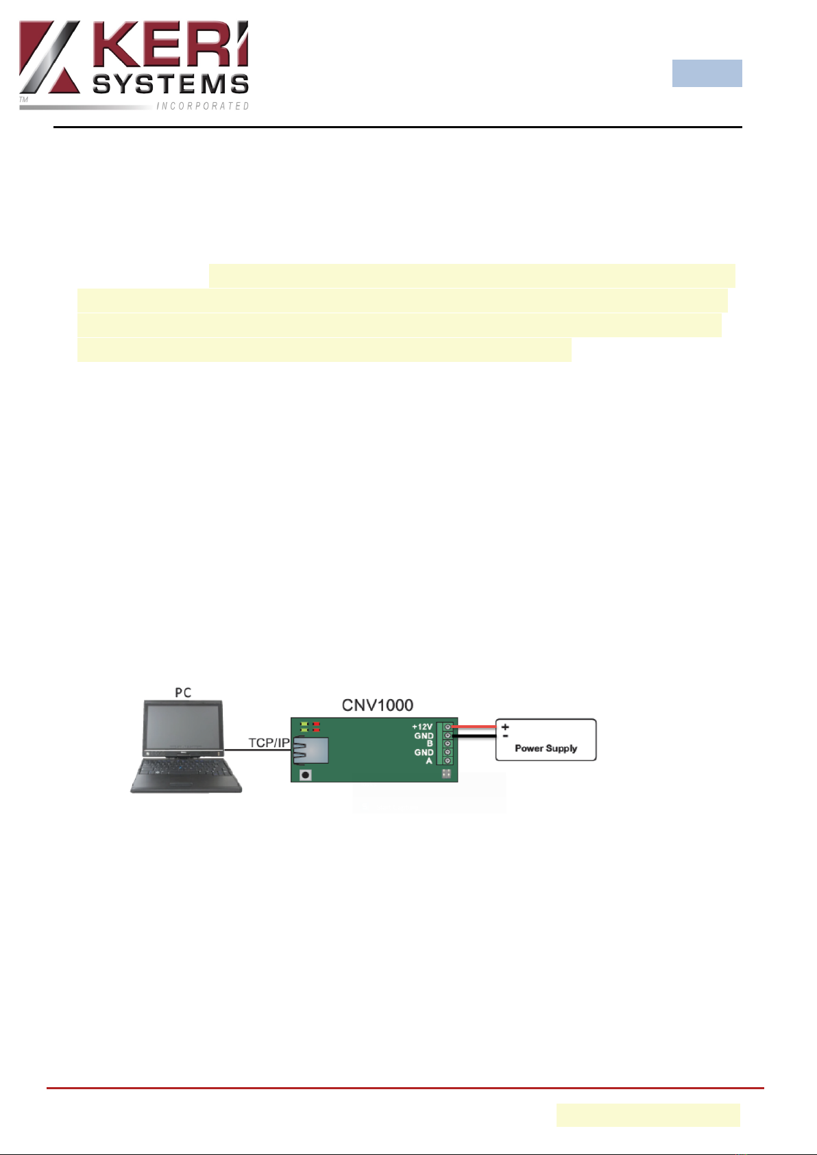
1. Apply 12VDC power to the CNV-1000.
2. Connect the host PC to the CNV-1000 using a cross-over cable or via a
hub/switch using a patch cable.
- Ethernet connection using a cross-over cable from the host PC
3. Connect the first BioSync to the CNV-1000 using the RS-485 connections.
BioSync
- 6 - P/N: 02303-001 - Rev. E
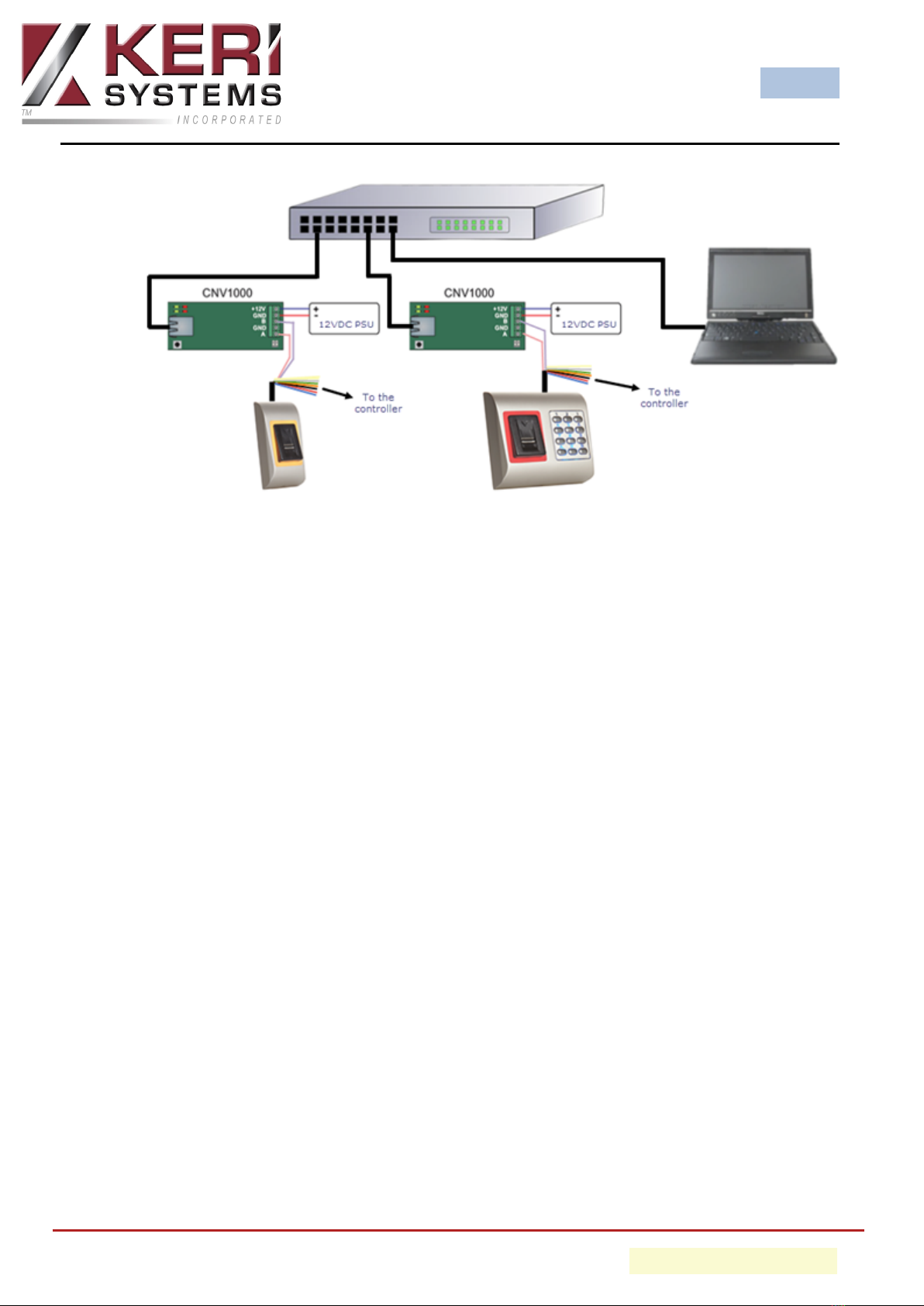
- Ethernet connection into a network switch using multiple CNV converters
4. Wire the BioSync reader into the RIM located on the controller (which should
be configured for Wiegand).
Note: For reader wiring information please refer to the Biosync reader setup
guide.
3.2 Connecting Multiple BioSync Readers
1. Apply 12VDC power to the CNV-1000.
2. Connect the host PC to the CNV-1000 using a cross-over cable or via a
hub/switch using a patch cable.
3. Connect the first BioSync to the CNV-1000 using the RS-485 connections.
4. Connect the second BioSync to the first BioSync by daisy-chaining the RS-485
connections.
5. Continue the RS-485 daisy-chain connection to other BioSync readers.
6. Wire the BioSync readers into the RIMs (which should be configured for Wie-
gand).

BioSync
- 7 - P/N: 02303-001 - Rev. E
4.0 CNV-1000 Host PC Connection
IMPORTANT: The CNV-1000 has a default IP address of 192.168.1.100 so for initial
connection and configuration you will have to set the host PC with an IP address in
the same IP range:
Consult an IT professional if you require assistance changing the host PC IP
address.
1. From Windows Control Panel, go to Network and Sharing Center.
2. On the left-side of the screen click on Change Adapter Settings.
3. Right-click Local Area Connection and choose Properties.
4. Highlight Internet Protocol Version 4 (TCP/IPv4).
5. Click the Properties button.
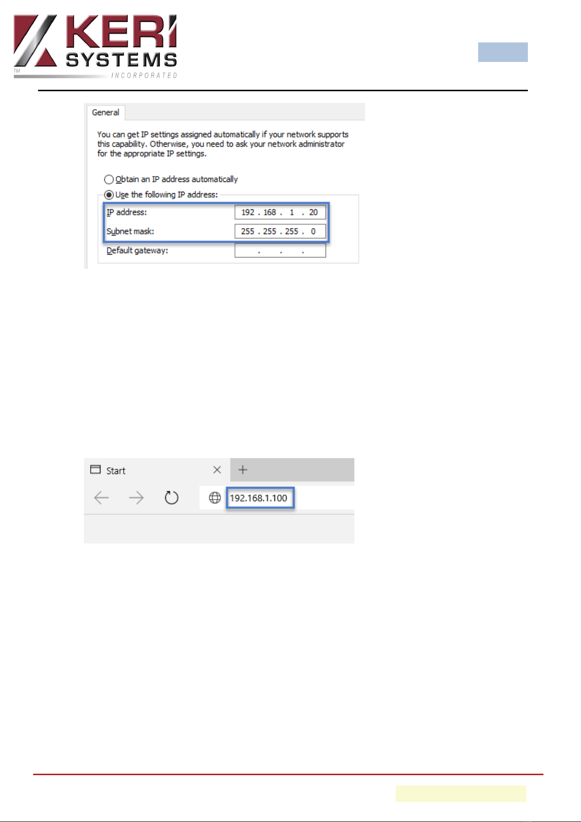
6. Verify that Use the following IP address is selected.
7. Enter an IP address on the range of 192.168.1.X (but not 192.168.1.100).
8. Press the tab key and the Subnet mask should auto-infill with 255.255.255.0
9. The default gateway fields should be left blank.
BioSync
- 8 - P/N: 02303-001 - Rev. E
10. You will now be able to connect to the CNV-1000 via a web browser.
5.0 CNV-1000 IP Address Change
1. Open a web browser and in the address bar, enter the default IP address for the
CNV-1000.
2. A login window will appear prompting you for a user name and password.
- Default user name = admin
- Default password = 00000000 (eight zeros)

BioSync
- 9 - P/N: 02303-001 - Rev. E
3. In the Settings section enter the IP address you wish to assign to the CNV-1000.
4. Then click on the UPDATE AND RESET button.
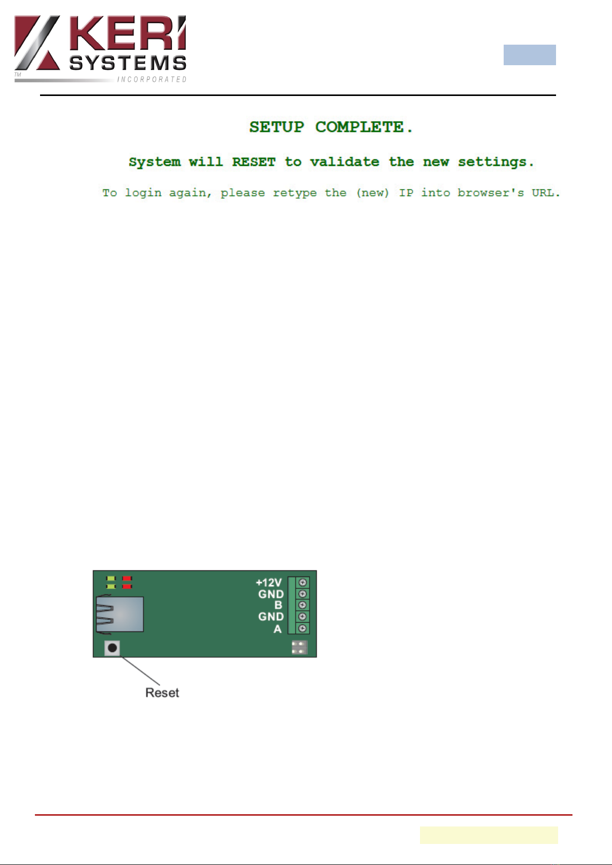
5. You will then see the following message:
BioSync
- 10 - P/N: 02303-001 - Rev. E
6. After a few seconds the CNV-1000 will be set to the new IP address.
Note: If the new address is on a different range to 192.168.1.X then you will need to
alter the host IP address again to be within the new range before you can connect to
the converter again. Follow the steps outlines in the previous section to change the
host IP address.
6.0 Factory Resetting the CNV-1000
The following steps will clear the converter's configuration and to set the IP address
back to the default of 192.168.0.100.
1. Remove the CNV-1000 cover and you will see the PCB.
2. Press and hold the black reset button for at least 5 seconds.
3. The second green LED should illuminate.
4. The converter is now reset (IP address, TCP port and the device password will be
at their defaults).
BioSync
- 11 - P/N: 02303-001 - Rev. E
7.0 Adding the CNV-1000 as a Portal
Within the BioManager software the converter is referred to as a portal. The portal
must be added before you can add the BioSync readers to the software.
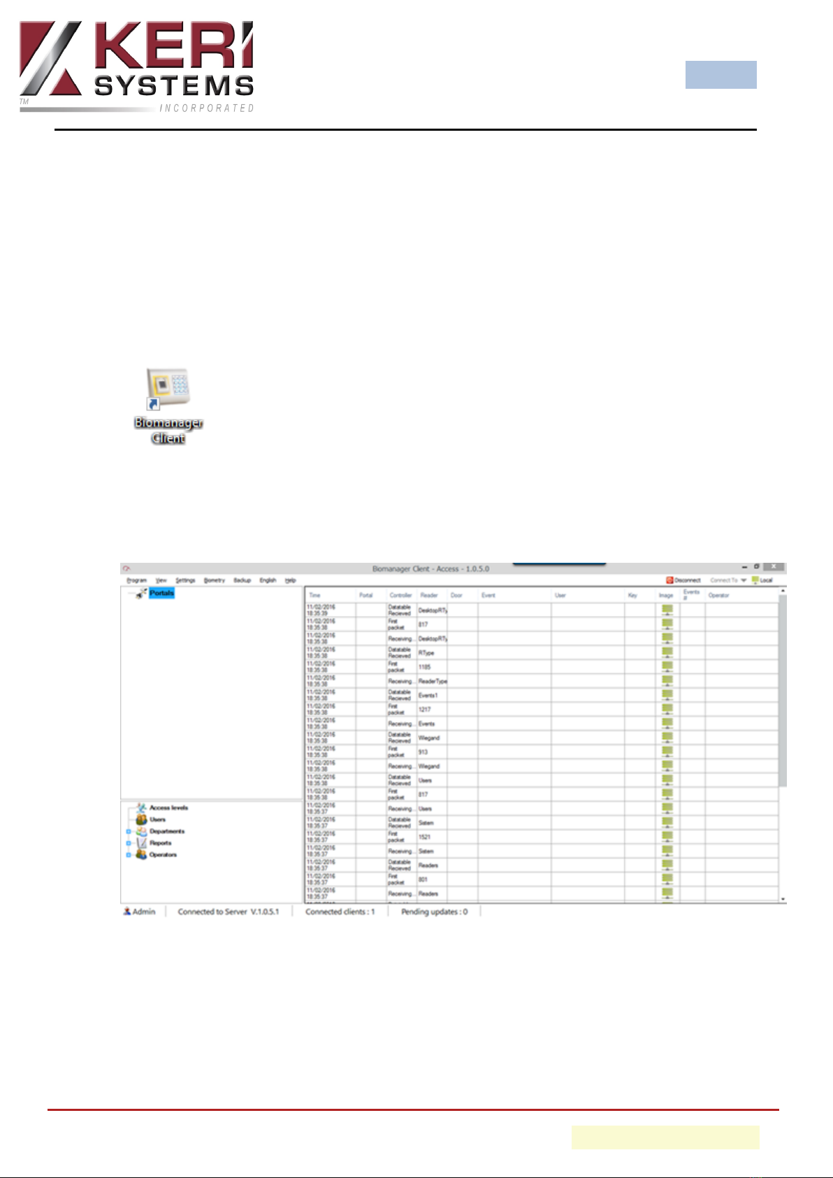
1. Click the BioManager client icon on the desktop.
2. If no operators have been setup then the user interface should open.
3. A general system events grid will be displayed on the main window pane.
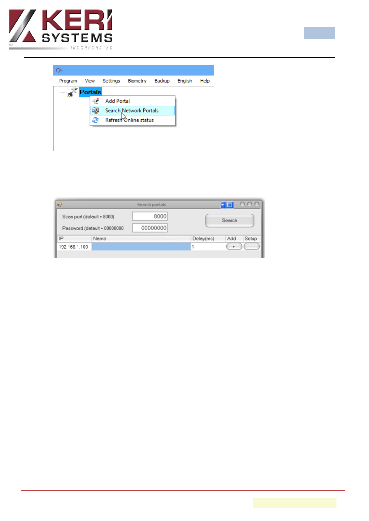
4. On the left of the screen you will see Portals.
5. Right-click Portals and select Search Network Portals.
BioSync
- 12 - P/N: 02303-001 - Rev. E
6. Click the SEARCH button and wait...
7. If the CNV-1000 is found it will be displayed in the table.
Note: You can also add the portal manually (via right-click - Add Portal), you
then simply type the IP address which is assigned to the CNV-1000).
8. Enter an 8 digit device password (factory default is 00000000).
9. Select the row with the portal listed and click on the Setup button to configure
it.
10. The setup portal window is shown with the portal settings.

BioSync
- 13 - P/N: 02303-001 - Rev. E
11. Enter New Settings:
- IP: IP address of device
- Setup port: Network port for search and setup. Changing is not recom-
mended.
- Password: Password for access to read and change the settings of the CNV-
1000. It is recommended to change the default password and use it for all con-
verters in the system.
- Mask: Enter the device subnet mask.
- Gateway: Default gateway.
- MAC: Physical address of the device. Changing is not recommended.
- DHCP Enable: Enable the DHCP client.
- DNS: Address of the DNS server.
- Data port: Port used for communication between BioManager and devices
behind the converter.
- Dedicated client: To forbid unauthorized access to devices connected to the

BioSync
- 14 - P/N: 02303-001 - Rev. E
portal from another system, select one of the following options: a) Disabled -
no source security checking, b) MAC only - the source MAC address must be
equal to the Dedicated MAC value, c) IP onlythe source IP address must be
equal to the Dedicated IP value, d) IP or MAC - at least one of the conditions
from point b and c must be true, e) IP and MAC - both b and c conditions must
be true.
- Enable web interface: enable or disable the CNV-1000 web interface for con-
figuration.
- Web port: Web interface port.
- Version: Read-only field displaying the firmware version of the converter.
12. Click on SEND SETTINGS to configure the CNV-1000, in a few seconds you should
see the results message notifying you that the settings have been successfully
changed.
13. You are now ready to begin adding your BioSync readers to the BioManager
software.
BioSync
- 15 - P/N: 02303-001 - Rev. E
8.0 CNV-1000 Firmware Upgrade Procedure
Perform the following steps to upgrade the firmware on a CNV-1000:
IMPORTANT NOTE: If the version is NOT greater than the detected version (being
used by the CNV-1000) then DO NOT change the firmware.
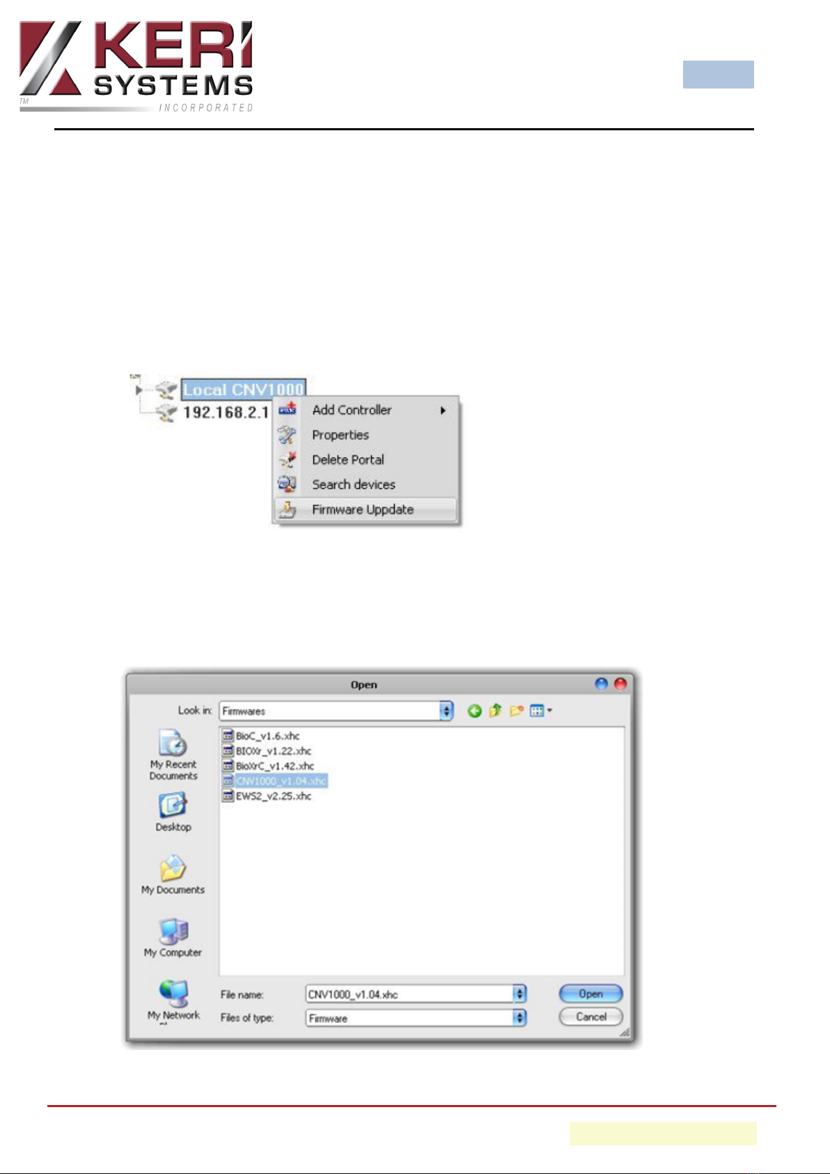
1. Right-click the portal to be updated and select the Firmware Update option.
2. On the firmware update window, click the Browse button. The default location
of the firmware files installed with BioManager will be in the BioManager "Firm-
ware" folder. If you have a newer version, use the Browse button to locate it.

BioSync
- 16 - P/N: 02303-001 - Rev. E
3. Select the firmware file with a "xhc" extension.
4. Check the firmware version.
5. Click on the UPLOAD button.
6. Wait for the "Update End" message.
7. Close the Firmware Update window.
BioSync
- 17 - P/N: 02303-001 - Rev. E
Contact Keri Systems
Keri USA Keri UK, Ireland, Europe
302 Enzo Drive. Suite 190, San Jose,
CA, 95138 USA
Unit 1, Main Road, North Burlingham,
Norwich, NR13 4TA, UK
Telephone: (800) 260-5265 (408) 435-
8400 Telephone: + 44 (0) 1763 273 243
Web: www.kerisys.com Web: www.kerisys.com
E-mail: sales@kerisys.com
techsupport@kerisys.com
E-mail: eusales@kerisys.com
eutech@kerisys.com
Borealis User Interface - keri.aetheros.net
Knowledge Base Website - help.kerisys.com
YouTube Channel - www.youtube.com/user/kerisystems
end of document
Table of contents
Other KeriSystems Media Converter manuals

Popular Media Converter manuals by other brands


H&B
H&B TX-100 Installation and instruction manual

Bolin Technology
Bolin Technology D Series user manual

IFM Electronic
IFM Electronic Efector 400 RN30 Series Device manual

GRASS VALLEY
GRASS VALLEY KUDOSPRO ULC2000 user manual

Linear Technology
Linear Technology DC1523A Demo Manual

Lika
Lika ROTAPULS I28 Series quick start guide

Weidmuller
Weidmuller IE-MC-VL Series Hardware installation guide

Optical Systems Design
Optical Systems Design OSD2139 Series Operator's manual

Tema Telecomunicazioni
Tema Telecomunicazioni AD615/S product manual

KTI Networks
KTI Networks KGC-352 Series installation guide

Gira
Gira 0588 Series operating instructions

Lika
Lika SFA-5000-FD user guide