Kewaunee Air Alert 600 Specification sheet

Air Alert 600
FUME HOOD VELOCITY ALARM
Operating and Installation Manual
Control Pushbutton functions
Velocity display fpm or m/sec
Velocity Bar Graph or
Alarm Time Line
AIR ALERT 600
•Digital display
•3 Relay inputs
•3 Relay outputs
•Com port
1
SEE P. 10 FOR CALIBRATION PROCEDURE!!!

Note:
Access to the Calibration and Configuration menus is password protected and is
factory-set. Default password is 0000. To change the password or other
parameters, obtain the alarm communication program from Kewaunee Scientific
(HTUwww.kewaunee.comUTH). Use a Laptop connected to the Com port and the
Upload/Download software to alter password or make other changes.
Connection details:
Relay output 1
Rated 240V
2A AC1
Com port
RS232
Relay input 1
PSU
Flying lead with plug
connection for PCB
15 V DC
Flying lead with plug
connection for PCB
and SM5 airflow sensor
12V DC
Flying lead from Proxy
switch with plug
connection for PCB
12V DC
Sash High
Proximity switch
( Optional )
Relay input 3
Relay input 2
R1
R2
R3
SENSOR
SOCKET
0-10V
ECON
OUTPUT
15V DC
POWER
SUPPLY
INPUT
0-10V
AUX.
OUTPUT
s/w
Sash Proximity
switch
OUTPUT RELAYS
COMMS
PORT
RELAY INPUTS
INPUT 1
INPUT 2
INPUT 3
Bn
Bk
Bl
Sash Micro
switch
REFER TO INSTALLATION
INSTRUCTIONS BEFORE CONNECTING
WARNING
Relay output 3
Rated 2 0V4
2A AC1
Relay output 2
Rated 240V
2A AC1
SM5
Airflow Sensor
2

1.1 General Description
All systems are comprised of the following components:
1 – SM5 In –line Airflow Sensor,
1 – AIR ALERT 600 Alarm unit,
1 – AC power supply
If the Sash Alarm System option is included there will also be a sash micro
switch or proximity switch.
UOperator FeaturesU--- the alarm has the following operator features:
UDigital Display
The digital display is a back-lit, full graphic unit with a visual display of approx.
2.25” x 1.25”. The display operates through the software allowing the generation
of figures, wording and Icons. The display shows the fume hood face velocity in
m/sec or fpm when enabled or the alternative with no velocity reading but
showing AIR FAIL / AIR SAFE as continuous display. All of the above are
configurable via the alarm key pad.
An ‘event time line’ segmented into 20, 3-minute segments will scroll across the
display when enabled.
This takes the form of a graphical ‘blip’ that will progress from the right-hand side
to the left-hand side, representing events that have occurred during the past
hour. On the standard alarm this will be limited to airflow alarms but other alarms
are available.
Using the diagnostics software and an associated computer via the com port on
the alarm the event data can be transferred to a data logger.
The alternative to the event time line is a dynamic ‘bar graph’ representing the
face velocity.
The display shows a Horn icon (with line through it) when the audible alarm is in
the Muted condition.
3

Condition Messages Displayed on Screen:
Sash High –will be displayed when the Sash alarm is enabled and the sash is
raised above the max safe working opening. This display will alternate on/off
with the velocity reading.
Ext Alarm – will be displayed when the external alarm input is activated ( when
enabled ) This display will alternate on/off with the velocity reading
Air Fail - will be displayed if the airflow is less than the Low air alarm point.
This display will alternate on/off with the velocity reading
High Air - will be displayed if the airflow is more than the High air alarm point.
This display will alternate on/off with the velocity reading
Set-back- will be displayed if the night set-back function is activated (when
enabled) This display will alternate on/off with the velocity reading.
Disabled - will be displayed if the alarm disable function is activated (when
enabled) This display will alternate on/off with the velocity reading
ULED IndicatorsU---- the alarm unit has three LED indicators:
Red -- Alarm
Amber -- Caution
Green -- Safe
UAudible Alarm sounderU-- the alarm has an audible alarm sounder with local or
remote mute facility
Buttons and Controls:
UEnter U--- the alarm has an Enter button -- this is multi-functional as follows:
Press Enter momentarily when alarm is sounding will mute the alarm
Press Enter for 5 secs will gain access to Calibration and
Configurationmenus ( both menus password protected )
U+ / - UThe alarm has + / - buttons that can be used to scroll through the
calibration and configuration menu or to select options or values
4

UExternal ConnectionsU:
Input 1 --- volt free relay input configurable for normally closed or normally
open relays
This input can be configured as:
Alarm disable
Night set-back
External alarm
Sash High
High / Low
Input 2 --- volt free relay input configurable for normally closed or normally
open relays
This input can be configured as:
Alarm disable
Night set-back
External alarm
Sash High
High / Low
Input 3 --- volt free relay input configurable for normally closed or normally
open relays
This input can be configured as:
Alarm disable
Night set-back
External alarm
Sash High
High / Low
Output 1 --- volt free relay output configurable as normally closed or
normally open relays.
Output 2 --- volt free relay output configurable as normally closed or
normally open relays.
Output 3 --- volt free relay output configurable as normally closed or
normally open relays.
5

Com Port --- to enable connection to Laptop or PC for full diagnostics,
logging or setting up and for communications to building computer system
(BMS)
Power supply --- low voltage DC power supply
Airflow Sensor --- connection socket for the face velocity airflow sensor.
1.2 Alarm Configuration / Calibration
The alarm can be configured via a Laptop or PC using a variety of ‘set up’
programs each designed for a particular application with a combination of inputs,
outputs and push buttons. This configuration can be changed via the alarm key
pad using the menu system if required or re-configured by re-connection of the
laptop or PC.
The configuration of the various functions and the calibration of the alarm face
velocity meter is menu-driven. Access to the menu will be via password (4 digit
number) and will be two-level. The first level will be for calibration of the unit and
the second level will be for set-up of the configuration of the alarm.
The menus and sub–menus are in plain language and incorporate brief
instructions where appropriate.
1.3 Start up
When unit is powered up, the following sequence of events occur:
1. The 12V DC power is applied to the airflow sensor and a delay on timer (30
sec) is initiated.
2. The alarm then performs a self-test on the display and all indicators etc
(approx. 5 sec)
3. The display show a ‘Welcome note’ – with the Kewaunee name for the rest of
the initial 30 sec delay time. During this time the airflow sensor is stabilizing.
4. During the whole of the 30 sec period all alarms and relay outputs are
inhibited.
6

5. At the end of the 30 sec delay the unit performs one of two options:
a. If the alarm calibration has been previously completed, the
unit goes to normal operating mode (Run)
b. If the unit has not been calibrated the unit displays:
‘Unit requires set up -- press Enter to access Set up menu’
The set up menu allows calibration or configuration via the password
protection
During the set-up all alarms and output relays are inhibited.
1.4 Events / Actions
Safe airflow
•Meter reading above warning level (> 0.90 FPM)
•Green LED on
Warning airflow
•Meter reads between warning level and air fail level (> 80 FPM and < 90
FPM)
•Amber LED on
Low airflow
•Meter reads below alarm level for longer than the warning to low air delay
time
•AIR FAIL toggles on / off with display
•Red LED flashes
•Audible alarm sounds -- can be muted via Enter pushbutton
•Low air relay operates if configured
Reset
•When airflow rises 4 fpm above Low air level for longer than the low air to
warning air delay time the Low air alarm resets automatically
Audible alarm Mute
•When the audible alarm is muted via the Enter button - an Icon (horn with
forward slash) is shown on the display.
7

Sash High
•When the input configured as Sash High is activated
•Amber LED on
•Sash High – toggles on / off with velocity display
•Audible alarm sounds
•Audible can be muted via Enter pushbutton -- this silences the alarm and
initiates a repeat timer (if configured). After the delay time the alarm re-
sounds ( and can be re-muted). During this time the Amber LED flashes on /
off.
•Sash High relay operates (if configured)
Reset when Sash lowered to safe position and input de-activated.
High / Low
•When input configured as High/Low is activated
•Display Icon shows High or Low
•High / Low relay operates (if configured)
This function is designed for two-speed fan operation or two position damper
operation switched via a micro switch or proximity switch activated at a given
position on the sash.
Night set-back
•When input configured as Night set-back is activated
•Night set-back Icon is displayed
•Red LED on (Flashing)
•Reduced Low air alarm (if configured)
•Audible alarm muted
•Mute Icon shown on display
External alarm
•When input configured as External alarm is activated
•Red LED on ( Flashing) – ( if configured )
•External Alarm toggles on /off with display -- ( if configured )
•Audible alarm sounds – can be muted via Enter pushbutton
•External alarm relay operates ( if configured)
Alarm disable
•When input configured as Alarm disable is activated
•Alarm disabled is displayed
•Red LED on ( Flashing)
•Audible alarm muted
•Mute Icon shown on display
8

2.1 Quick Start Installation
Follow the instructions below for installing and commissioning the unit. :-
1. Fit the alarm to the Fume Hood using the cut-out details provided with the
unit see page 12
2. Fit the airflow sensor to the Fume Hood using the cut out and installation
details provided --- see page 10
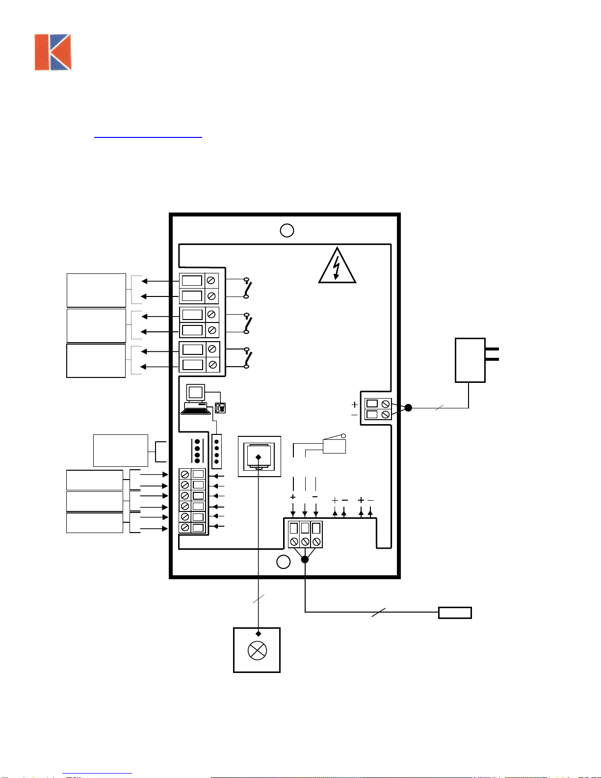
3. Connect the ‘telephone style’ airflow sensor plug-in cable to the sensor
and the back of the alarm unit --- see typical connection diagram on page
11
4. Plug in the power adapter to a Mains AC power socket and connect the
flying lead to the alarm unit --- see typical connection diagram on page
11.
5. Power up the unit and wait at least 30 sec. while the sensor temperature
stabilizes.
6. If the unit has not been calibrated the unit will display ‘Requires setup’ –
press ENTER to continue and in the Main Menu use the +/- buttons on the
alarm facia select ‘SETUP’ and then press the ENTER button.
7. In the ‘Setup Menu’ select ‘CALIBRATION’ and press the ENTER button
8. At this stage you will be requested to enter the PASSWORD. Use the +/-
buttons to select the individual digits in turn and then press ENTER.
If the password is correct the unit will go to the calibration mode. If the
password is not correct you will be requested to try again --- on the third
wrong password entry the calibration menu will lock out for 10 minutes.
From the factory, default password is set for 0000.
9. When in the calibration mode follow the instructions on the display screen
to carry out the calibration of the unit. See ‘Calibration Notes’ below for
hints on successful calibration.
When the calibration is complete the unit will return to the Main Menu.
10.Use the +/- buttons on the alarm face; select ‘ RUN ’ and then press the
ENTER button.
The unit will now function and display the measured Fume Hood face
velocity
9

2.2 Calibration Procedure:
1. When using a standard Fume Hood with Vertical Sliding sashes, open the
sash to the normal max safe working height for the Low Air sample.
2. For the Higher Air sample close the sash to approx. 50% of the opening
used for the Lower Air sample. If the Higher air sample value is too close
to the Lower Air sample the alarm will detect this and ask you to repeat
with a higher value. To do this, close the sash a little more and repeat the
sample. Avoid closing the sash below 4 inches.
3. The face velocity readings on the open sash may vary at different points
on the measuring grid by up to 20 FPM. This is quite acceptable in terms
of the fume hood performance, so long as no individual point is below the
designated Low Air alarm point. The figure entered for the calibration point
should be taken as the average value of all the measuring grid readings.
4. Take time when measuring the face velocities for the calibration procedure
to allow for the velocities across the open sash to stabilize. If the velocities
are changing or are turbulent during the sampling period the alarm will
detect this and ask you to repeat the sample.
5. When using a Fume Hood with Horizontal Sliding sashes, open the
sashes to the normal max safe working opening for the Low Air sample.
10

3.0 AIR ALERT 600 -- CUTOUT AND ALARM DIMENSIONS
Alarm Panel
Cutout
Dimensions
4 7/16” x 3 11/32”
4 5/8” 5”
3 11/32”
3/16”
3/16”
2 x Fixing Holes for
Alarm Plate Screws
Hole size 5/32” for No 4
Self-tapping screw provided
8 21/32”
Sensor Tube
Cutout
Dimensions
1” diameter
Fume hood
Side Airfoil
( Front view )
Center
Line
3.5”
5 13/16”
Alarm Panel
Dimensions
11

4.0 INSTALLATION DETAILS
12

5.0 WIRING DIAGRAM
Relay output 1
Relay output 2
Relay output 3
Input 3
Input 2
Input 1
9
8
7
6
5
4
3
3
2
2
1
1
AIR ALERT 600
Com port
SM5 In-line
Airflow Sensor
Flying lead with
plug connection
for PCB
and SM5 airflow
sensor
12V DC
12
11
10
Optional Sash High
Proximity switch
Flying lead with plug
connection for PCB
12 V DC
120V
PSU
120V / 12V DC
Plug – in power
adaptor for 120V
socket
Flying lead from Proxy swith with
plug connection for PCB
12V DC
KEWAUNEE SCIENTIFIC CORPORATION ph. 704 873 7202
13
Other manuals for Air Alert 600
1
Table of contents
Other Kewaunee Security System manuals
Popular Security System manuals by other brands

suprema
suprema BioStation 2 installation guide

EMC Services
EMC Services Zero Wire manual

Lorex
Lorex HD14S1042-A instruction manual

IDESA
IDESA ideTronic HPS 841 Using instructions

Home Automation
Home Automation INC. Omni IIe owner's manual

Inhep Digital Security
Inhep Digital Security IDS X Series user manual