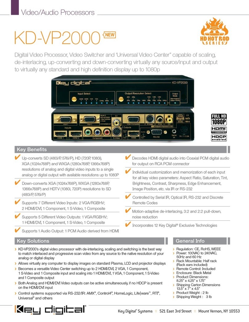
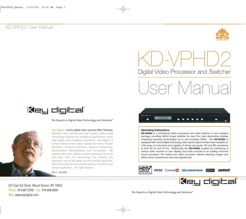
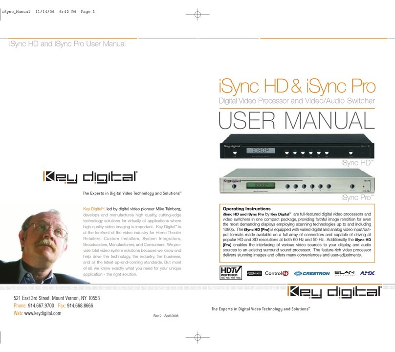
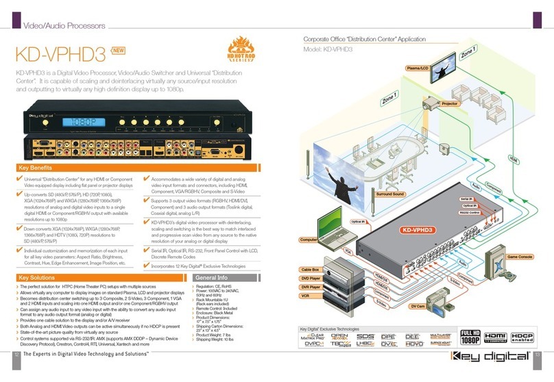
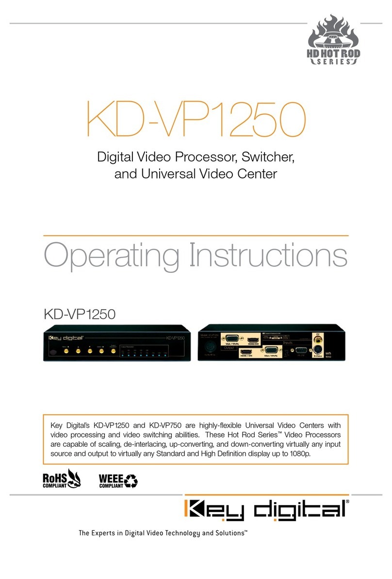
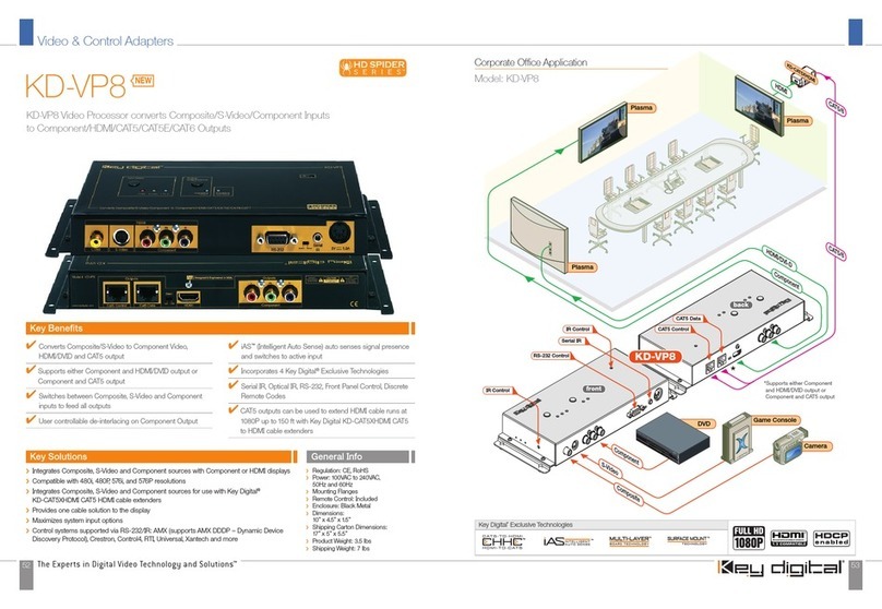
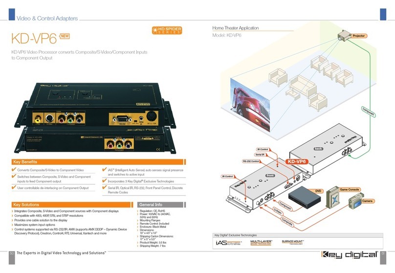
Key Digital KD-VP6 User manual

521 East 3rd Street, Mount Vernon, NY 10553
Phone :: 914.667.9700 Fax :: 914.668.8666
Web :: www.keydigital.com
KD-VP6 & VP8 Operating Instructions
Operating Instructions
Key Digital
®
, led by digital video pioneer Mike Tsinberg,
develops and manufactures high quality, cutting-edge
technology solutions for virtually all applications where
high quality video imaging is important. Key Digital
®
is at the forefront of the video industry for Home
Theater Retailers, Custom Installers, System Integrators,
Broadcasters, Manufacturers, and Consumers. We
provide
total video system solutions because we
know and help drive the technology, the industry, the
business, and all the latest up-and-coming standards.
But most of all, we know exactly what you need for your
unique application - the right solution.
Rev 0 – December 2006
Key Digital
®
KD-VP Spider Series
™
Video Processors convert standard definition NTSC
480i, 480p and PAL 576i, 576p analog video sources to component video. Additionally,
the KD-VP8 includes HDMI and HDMI over CAT 5 outputs. KD-VP’s feature IAS
™
Intelligent
Auto Sense signal detection and switching, pushbutton control, status-monitoring LED’s
and RS-232 and IR remote control. KD-VP processors are expandable, individually
addressable, and the KD-VP8 is DVI-D compatible when used with Key Digital
®
adapters
and cables. Spider Series
™
products are engineered to meet rigorous Key Digital
®
design
and test criteria to produce crystal-clear, pristine picture quality.
KD-VP6
Digital Video Processor
KD-VP8
Digital Video Processor
KD-VP6 KD-VP8

KD-VP6 & VP8 Operating Instructions
Page 2
KD-VP6 & VP8 Operating Instructions
Page 1
Read these instructions.
Keep these instructions.
Heed all warnings.
Follow all instructions.
Do not use this apparatus near water.
Clean only with dry cloth.
Do not block any ventilation openings. Install in accordance with the manufacturer’s
instructions.
Do not install near any heat sources such as radiators, heat registers, stoves, or other
apparatus (including amplifiers) that produce heat.
Do not defeat the safety purpose of the polarized or grounding-type plug. A polarized plug
has two blades with one wider than the other. A grounding type plug has two blades and
a third grounding prong. The wide blade or the third prong are provided for your safety. If
the provided plug does not fit into your outlet, consult an electrician for replacement of the
obsolete outlet.
Protect the power cord from being walked on or pinched particularly at plugs, convenience
receptacles, and the point where they exit from the apparatus.
Only use attachments/accessories specified by the manufacturer.
Unplug this apparatus during lightning storms or when unused for long periods of time.
Refer all servicing to qualified service personnel. Servicing is required when the apparatus
has been damaged in any way, such as power-supply cord or plug is damaged, liquid has
been spilled or objects have fallen into the apparatus, the apparatus has been exposed to
rain or moisture, does not operate normally, or has been dropped.
1.
2.
3.
4.
5.
6.
7.
8.
9.
10.
11.
12.
13.
Important Safety Instructions.
Please be sure to follow these instructions for safe operation of your unit
TABLE OF CONTENTS
About the KD-VP6 and KD-VP8 ................................................. 2
KD-VP Features ............................................................. 3
What’s Included ............................................................. 4
Installation ................................................................. 6
Basic Operation.............................................................10
IR Remote Control ...........................................................13
Firmware Upgrades ..........................................................14
Terminology ................................................................15
Technical Specifications ......................................................16
How to Contact Key Digital
®
....................................................18
© 2006 Key Digital, Inc. All rights reserved.
WARNING: TO PREVENT FIRE OR ELECTRIC SHOCK,
DO NOT EXPOSE THIS APPLIANCE TO RAIN OR MOISTURE.
C A U T I O N
risk of electric shock
do not open
The lighting flash with arrowhead symbol, within an
equilateral triangle, is intended to alert the user to the
presence of uninsulated “dangerous voltage” within the
product’s enclosure that may be of sufficient magnitude
to constitute a risk of electric shock to persons.
The exclamation point within an equilateral triangle
is intended to alert the user to the presence of
important operating and maintenance (servicing)
instructions in the literature accompanying the
appliance.
cAUtion: TO REDUCE THE RISK OF ELECTRIC SHOCK, DO NOT REMOVE COVER (OR BACK).
NO USER-SERVICABLE PARTS INSIDE. REFER SERVICING TO QUALIFIED SERVICE PERSONNEL.

KD-VP6 & VP8 Operating Instructions
Page 2
KD-VP6 & VP8 Operating Instructions
Page 3
ABOUT KD-VP6 & KD-VP8 VIDEO PROCESSORS
Thank you for purchasing a Spider Series
™
Video Processor by Key Digital
®
.
The successful installation and operation of your Spider Series
™
KD-VP video processor with your
entertainment system is very important to us at Key Digital
®
. To take full advantage of the product
features, and to ensure you are obtaining the maximum picture quality, please follow all of the
instructions provided and contact Key Digital
®
at tech@keydigital.com immediately if you encounter
any difficulties.
Your Spider Series
™
KD-VP6 and KD-VP8 video processors from Key Digital
®
converts analog
standard definition NTSC 480i, 480p and PAL 576i, 576p sources to component video.
Additionally, KD-VP8 offers (user selectable) HDMI and HDMI over CAT5 output interfaces. HDMI
can be converted to DVI-D when used with Key Digital adapters and cables.
The KD-VP6 and KD-VP8 are video processors only and do not accept or output any audio. Audio
must be connected appropriately, bypassing the KD-VP unit.
All the features of KD-VP video processors can be controlled via top-panel pushbuttons, side
mounted slide switches, IR remote control, wired IR or RS-232. Top and side mounted LED’s
enable you to monitor the status of your selections.
Always follow the instructions provided in this Operating Manual.
KD-VP6
KD-VP8
KD-VP FEATURES
Converts Composite, S-Video and Component video to Component output
Converts Composite, S-Video and Component video to HDMI output (KD-VP8 only)
HDMI or HDMI over CAT5 output selectable via a slide switch (KD-VP8 only).
Accepts analog SD NTSC 480i, EDTV 480p, PAL 576i and EDTV 576p video formats
Offers user controlled de-interlacing available on Component output only
IAS
™
Intelligent Auto Sense switches to active input
Pushbutton control, and the corresponding status LEDs
Easy-to-operate IR remote control
Wired IR remote control port
RS-232 control port, compatible with all control systems
Field upgradable firmware [see note 1]
Built-in mounting flanges
[1] Contact Key Digital
®
(tech@keydigital.com) with the Serial Number of your unit to determine the correct Firmware
Upgrade procedure for your unit. Check our web site at www.keydigital.com for Firmware Upgrade instructions and
notification of any available Firmware Upgrades for your unit.
Explanations of technical terms can be found in the Terminology section of these instructions.
Technology
Key Digital
®
technology allows us to deliver the highest level of picture quality attainable in all of our
products, like the proprietary technology we engineered for you into the KD-VP:
WHAT’S INCLUDED
The carton contains:
One KD-VP6/8 processor unit
Separate external 5-Volt power supply
IR remote control with batteries included
Operating Instructions
Warranty card
›
›
›
›
›
›
›
›
›
›
›
›
1.
2.
3.
4.
5.
Key Digital
®
Exclusive Technologies Supported Technologies
CAUTION: When installing the unit, make all video connections before plugging
in the external power supply provided with your unit. Do NOT apply power to the
unit until all video and audio connections have been made to your KP-VP unit from
the “source” devices to the display(s) and/or devices. You MUST use the external
power supply provided with your unit or you VOID the Key Digital
®
Warranty and
risk damage to your unit and associated equipment.

KD-VP6 & VP8 Operating Instructions
Page 4
KD-VP6 & VP8 Operating Instructions
Page 5
A Typical KD-VP6 interface configuration for input (source) devices
and the output (sink) display, with audio bypass, of your installation.
A Typical KD-VP8 interface configuration for input (source) devices
and the output (sink) display, with audio bypass, of your installation.
Component
Projector
VCR Game Console
Camera
KD-VP6
back
front
Component
S-Video
Composite
RS232 Control
Wired IR
IR Control
IR Control
HDMI/DVI-D
HDMI
Composite
CAT5
VCR Game Console
Camera
KD-VP8
back
front
Component
S-Video
Composite
*To connect DVI Video use
HDMI < > DVI adapter cables
RS232 Control
Wired IR
IR Control CAT5 Control
CAT5 Data
IR Control
Plasma
Plasma
Plasma
KD-CAT5xHDMI

KD-VP6 & VP8 Operating Instructions
Page 6
KD-VP6 & VP8 Operating Instructions
Page 7
2. Connect your source devices to the input ports of your KD-VP unit.
Connect the Composite (CVBS), S-Video and Component Video sources to the inputs of your VP
unit. (Note: Audio must bypass the VP unit.)
The INPUT connectors accept
Composite, S-Video and/or
Component video sources.
The INPUT connectors provide component
video. The KD-VP8 (pictured) also supports (user
selectable) HDMI or HDMI over CAT 5 outputs.
Do not connect the external supply (provided) to the back of the
KD-VP6/8 unit until ALL of your video and audio connections are
completed.
3. Connect your Display (or sink device) to the output of the KD-VP unit.
Connect the Component, or for a KD-VP8 the HDMI, output to your display. (Note: If the display
has only a DVI-D connector, then you can use a Key Digital
®
HDMI to DVI-D adapter at the KD-VP8
output, followed by a DVI-D cable, to connect to the DVI-D input of the display.)
When using KD-VP8 for HDMI or HDMI over CAT5 output select either “HDMI” or “Cat5” using the
slide switch located between the HDMI and CAT5 jacks for the desired output format. (Refer to the
“HDMI to DVI-D Conversion” section later in these instructions for more information.)
4. Connect the Control inputs to your KD-VP unit.
Pushbutton Switch
Your KD-VP unit may be controlled using the pushbutton switches on the top of the unit:
“Input Select” pushbutton cycles through CVBS, S-Video and YPbPr sources
“Analog Output Control” toggles between interlaced (SDTV) and progressive (EDTV)
Side and top LED’s indicate your selections and status
IR remote control
The KD-VP can also be operated using the IR remote control provided with your unit:
Side and top IR sensors
Install the batteries as indicated in the hand-held IR remote control unit.
IR extender
Either mount the IR extender on the side of the KD-VP unit or connect a wired serial connector
cable if the connector is enabled in your unit:
Wired IR serial connector provided, uses a Xantech compliant interface
Use a 3.5mm male-to-male mono cable to connect to the wired IR Extender to the KD-VP.
›
›
›
›
›
›
Wired IR Extender KD-VP Unit
3.5mm male-to-male mono cable
INSTALLATION
Your KD-VP processor by Key Digital
®
is easy to configure and operate. In this section, you will
connect video devices to your KD-VP unit. These are the topics covered in detail in this section of
the Operating Manual. Please follow these instructions for the proper installation of your KD-VP unit:
Find a safe and convenient location to secure, mount, or place your VP unit.
Connect your composite, S-video and/or Component source device(s) to the input(s)
of your VP unit.
Then connect your Component, HDMI or CAT 5 (VP 8 only) Displays or other sink
devices to the output(s) of your KD-VP unit.
Audio must be routed separately from each of your video sources to your display or
audio system, bypassing the KD-VP unit.
Connect the Control inputs to your KD-VP unit, if desired.
Be sure the Operation Mode Switch is set to the “Normal” position.
Finally, connect the power supply provided with your KD-VP unit.
1. Find a safe and convenient location for your VP unit.
A KD-VP unit dissipates power during normal operation, thereby it is recommended to leave
enough ventilation space to provide sufficient airflow and cooling, especially if you are going to
leave the unit “On” most of the time. Do not cover the ventilation openings on the side of the unit.
Important notes about digital Cables and Cable lengths:
1.
2.
3.
4.
5.
6.
7.
Convenient mounting flanges are built into
the unit. Use proper care to secure the unit
to walls or other surfaces, using appropriate
anchors and/or mounting hardware [not
included with your unit].
CAUTION: Always test first, before permanently installing the KD-VP
Always test the picture quality, integrity of the connections, and overall operation
before permanently installing any new component in your system, and especially
before cables are pulled behind walls or ceilings.
It is recommended that you always use high-quality HDMI (or DVI-D, if applicable)
cables, like those available from Key Digital.
Limitations of the HDMI devices and/or the use of inferior cables may further restrict
the length of your cable runs.
When using an HDMI cable extender, like the Key Digital
®
KD-HDB150, always
test first for proper operation and error-free picture & audio quality, and follow the
instructions provided with the unit for proper installation and configuration.
➔
➔
➔
KD-VP6 & VP8 Operating Instructions
Page 8
KD-VP6 & VP8 Operating Instructions
Page 9
5. Be sure the Operation Mode Switch is set to the “Normal” position.
Once you have made all the video connections to your KD-VP, be sure the Operation Mode Switch
located on the side panel of the unit is to the “Normal” position.
The slide switch labeled “Operation” is a
Mode Switch that must be set to “Normal” for
proper operation of your unit. Slide the switch
to the “Mode A” position ONLY if you perform
a Firmware Upgrade. Check our web site at
www.keydigital.com for Firmware Upgrade
instructions and notification of any available
Firmware Upgrades that you may want to
install in your unit.
If necessary, slide the Operation Mode Switch located on the side of your unit to
the “Normal” position for proper operation. Do NOT slide the switch to the Mode
A position and apply power, or you may start a Firmware Upgrade of your unit. If
you do so, immediately disconnect power from your unit and contact Key Digital
®
.
6. Finally, connect the power supply provided with your KD-VP unit.
When all equipment is connected to your KD-VP and you have verified that the Operation Mode
switch is in the “Normal” position, you may now plug in the external 5 VDC @ 5 Amp Power Supply
(provided with your unit) to the jack on the back of the unit. Then connect the power cord from the
power supply into an appropriately rated wall outlet or power strip.
You MUST use the Power Supply provided with your unit or you
VOID the Key Digital
®
Warranty and risk damage to your unit and
associated equipment.
Control Options for KD-VP Video Processors
Wired IR Extender
Main IR Sensor
RS-232
Key Digital®Exclusive Technologies Supported Technologies
Side View
Second IR Sensor (without lens cover) can be used
in conjunction with IR Extender (like Xantech) or to
operate the unit with your IR Remote control
RS-232 Commands
The table below lists the RS-232 Commands that allow you to control your KD-VP video
processing unit operating at a Baud Rate of 57,600, 8 Data Bits,1 Stop Bit and No Parity.
Command Name Description Usage
h help
s status
pn power on
pf power off
i select source input i<1~3, a>
i1 = CVBS
i2 = S-Video
i3 = YprPb
ia = Auto-select
l lock buttons
u unlock buttons
rl IR remote lock
ru IR remote unlock
d Address assignment d<00~99>
d00 for stand-alone mode
sd Analog SDTV output enable
ed Analog EDTV output enable
Carefully insert the power
supply connector to the
back of your VP unit.
Multiple KD-VP Unit Configuration
Up to 99 individually addressable units can be installed. This capability can be configured only via
the RS-232 port.
“00” is the address for a stand-alone unit.
To assign a new address to a unit issue the command:
“d<00~99>”.
For example, to assign address “01” to a unit, enter: “d01”.
After configuration of multiple units is complete the IR remote can be used to control any KD-VP.
The IR command sequence to switch to input 2 of unit at address “01”:
“0” -> “1” -> “Input 2”
›
›
›

KD-VP6 & VP8 Operating Instructions
Page 10
KD-VP6 & VP8 Operating Instructions
Page 11
3a. Analog Output
Component video is available at the RCA output connectors. The ”Analog Output Control”
pushbutton enables you to toggle between interlaced (SDTV) and progressive (EDTV) output until
you reach the desired format. Your selection will be indicated by the “Progressive Output” LED on
the top of the unit.
Note: If the input is interlaced then it is possible to configure the Component output as progressive,
however if the input is progressive, then the output will always be progressive and the interlaced
configuration is not possible.
Input Format Progressive Input Active LED Analog Output Control LED Progressive Output
480i OFF ON ON
OFF OFF
480p ON N/A ON
576i OFF ON ON
OFF OFF
576p ON N/A ON
BASIC OPERATION
This section of the Operating Manual guides you on how to use your KD-VP processor with the top
mounted pushbutton switches. LEDs are provided in two convenient (top and side) locations so
that you can monitor the status of your selections.
1. User Control.
Since your processor supports multiple analog format input sources for video that will be converted
to Y Pb Pr component format, you need to make the following selections:
Select the input source that you want to send to your display.
Composite S-Video Component
LEDs correspond to the selection of the input Switch Control
3b. Digital Outputs (KD-VP8 ONLY)
HDMI and CAT5 outputs are available (without Audio). Either HDMI or CAT5 can be enabled at any
given time. The selection is made via “Select” switch on the back of the unit.
The video format available at the digital outputs is always the same as that at the selected input.
Interlaced to Progressive Conversion DOES NOT apply to digital outputs.
IAS
™
Intelligent Auto Sense will detect and switch to an active source input, automatically.
The KD-VP will sequentially cycle through the inputs until an active source is located. The IAS
feature can be ONLY activated via IR remote or RS-232.
A progressive video source (480p or 576p) will be indicated by an LED on the top of the unit.
Using the “Input Select”
pushbutton, cycle through
selection of all input sources.
Monitor each selection with
the LEDs located on the top
and side of your unit.
INPUT SWITCH CONTROL
pushbutton selects the input
Source that you want to send to
your displays and audio systems.
LEDs show your selection.
Top of the Unit
LEDs indicate the type
(Progressive or Interlaced)
of the selected active input
Top of the Unit
Analog Output Control
Selects the Output type
(Progressive or Interlaced)
LEDs show your selection.
CAT5 outputs must be used with Key Digital
®
BobCAT
™
Series CAT5-to-HDMI
converters ONLY. “CAT5 Data” and “CAT5 Control” ports must be connected the
respective ports on the BobCAT
™
Series converters.
CAT5 Control CAT5 Data CAT5/HDMI
Select switch
HDMI
2. Input Selection
Pushbutton control allows you to cycle through the inputs until you reach your desired selection.
Carefully depress the “Input Select” pushbutton and release. The LED’s monitor your selection.
Select the input source that you want to send to your display.

KD-VP6 & VP8 Operating Instructions
Page 12
KD-VP6 & VP8 Operating Instructions
Page 13
IR REMOTE CONTROL
The functions of the KD-VP can be remotely accessed using the IR remote control supplied with
your unit. The status-monitoring LEDs on the KD-VP will light to indicate the selections you make
with the IR remote control, just like when you use the pushbutton switches or RS232.
The IR remote control unit is based on Infrared technology, so you need a clear line-of-site
from the handheld control to the IR sensors located on the KD-VP. Always point the front of the
remote control directly at the IR sensors located on the KD-VP unit.
Be sure that you have installed the batteries in the handheld remote control unit. Periodically
replace batteries in the handheld unit, as the operational distance of the remote control is
affected by a weakened power source.
The following figure of the IR remote control that is provided with your KD-VP unit indicates the
functions of each pushbutton and hence all of the functions you can remotely control.
›
›
IR Extender
You may also want to use an IR extender, like those available from Xantech:
A rear panel sensor is provided without directional lens, perfect for Xantech IR extender
A wired IR serial connector is also provided
You’ll need to either mount the IR extender on the side of the KD-VP unit, or connect the serial
connector cable if the connector is enabled in your unit.
›
›
Wired IR Extender KD-VP Unit
3.5mm male-to-male mono cable
IR Remote Control buttons
ON
Turns Unit On
OFF
Turns Unit Off
Input Select Scroll Up
Input Auto Select (IAS™)
Input Select Scroll Down
Input Select
Output Select
Reserved for
Future Use
Numeric Keypad
Used in addressable
mode for specifying
unit’s address
HDMI to DVI-D Conversion
If a display or device you would like to connect to your KD-VP8 unit has only DVI-D connectors,
then you should use Key Digital
®
HDMI to DVI-D adapter between the KD-VP6/8 HDMI output and
a DVI-D cable connecting to the DVI-D connector on your display. Note that while HDMI supports
both video and audio over an HDMI cable, the signal from KD-VP6/8 only carries video.
DVI-D Displays
If your display does not support HDMI but has a DVI-D input,
you will need an HDMI to DVI-D Adapter at the output of the KD-VP8.
The Key Digital
®
HDMI to DVI-D Adapter is the perfect choice.
Key Digital HDMI to
DVI-D Adapter
Destination
DVI-D Input
Source HDMI
Output on KD-VP8
Use extreme care when adapting HDMI to DVI-D.
Always use an adapter at the source (that is, at the start of the run), test first
before installing permanently in your system, and restrict your cable lengths
as follows:
75-foot maximum cable length for 480p or 576p video resolution DVI-D cables
driven from HDMI with an HDMI to DVI-D adapter.
Cable length extenders must be installed per their product instructions and must be
tested before permanent installation.
➔
➔

KD-VP6 & VP8 Operating Instructions
Page 14
KD-VP6 & VP8 Operating Instructions
Page 15
TERMINOLOGY
Some of the terms and acronyms that you will see recurring in this Key Digital
®
VP processor
Operating Manual are listed below.
EDID Extended Display
Identification Data
EDID is a VESA standard data format that contains basic
information about a monitor and its capabilities. Information
includes vendor information, maximum image size, color
characteristics, factory pre-set timings, frequency range limits, and
character strings for the monitor name and serial number.
HDMI High-Definition
Multimedia Interface
HDMI is an uncompressed, all-digital audio/video interface that
supports over one cable standard-, enhanced-, and high-definition
video, and multi-channel audio. It is backward compatible with
DVI-D for the video portion, using simple adapters.
IR Infrared IR, like the Infrared remote control. Simply point the front of an IR
remote control unit towards the IR sensor on the product to be
controlled.
LED
LEDs (light-emitting diodes) are like small light bulbs that light up
to indicate a selection, and are used as status indicators.
N/A Not Applicable N/A
FIRMWARE UPGRADES
From time-to-time, Key Digital
®
provides updates for the Firmware that operates and controls
your KD-VP. These updates are optional, and you should only perform upgrades as provided and
instructed by Key Digital
®
. Periodically check our web site at www.keydigital.com for the latest
firmware updates for your unit.
You will then be instructed to go to our web site at www.keydigital.com for the Firmware Upgrade
instructions and file downloads.
Firmware Upgrade Procedure
Please review all steps first, before proceeding to upgrade your Unit.
Make sure you have the required equipment for upgrade:
a. PC with a serial port capable of 19200 Baud rate
b. Straight male-female DB9 serial cable (Null-modem NOT supported)
no longer then 10 ft.
Set the rear-panel Mode slide switch to “Mode A” mode.
Check our web site at www.keydigital.com for the latest firmware update ZIP file. Download
and unzip the firmware ZIP file to any directory on your PC. All of the unzipped files that are
created MUST be located in same directory on your PC.
Make sure that no devices are using the COM1 serial port on your PC.
Connect an RS-232 cable to the COM1 serial port on your PC, and the other end to the
RS-232 port on the rear panel of the KD-VP unit.
Double-click the “VPxx.BAT” file. The command mode window should pop up. Use this
pop-up window to monitor the progress of the Firmware Upgrade.
If an error occurs, check your RS-232 connection and repeat all of the above steps.
When the download is complete, disconnected the power supply form your KD-VP unit.
The power supply MUST be disconnected (either from the back of your unit or from the wall
outlet) to have a complete power shutdown - reset.
Disconnect the RS-232 cable between the unit and your PC
With the power disconnected, set the rear-panel Mode slide switch to “Normal” mode.
Reconnect the power supply to your KD-VP unit. The Firmware Upgrade is complete, and
your KD-VP unit is ready for operation.
1.
2.
3.
4.
5.
6.
7.
8.
9.
10.
11.

KD-VP6 & VP8 Operating Instructions
Page 16
KD-VP6 & VP8 Operating Instructions
Page 17
Status and Control
User-selectable input video source:
Pushbutton control, and corresponding LED’s for status
User-selectable HDMI or CAT5 Data & Control Output (KD-VP8 Only)
Progressive (EDTV) or Interlaced (SDTV) output mode LED indicator
LED indicates Progressive Input Active
IR remote control:
Separate front- and rear-panel IR sensors provided
Wired IR serial connector provided
RS-232 port:
Compatible with all control systems: Crestron, AMX, Elan, Control4, etc.
Used for Firmware upgrades
Each unit (up to 99 on the same IR network) is individually addressable using
the IR remote control
Mechanical
Operating Temperature Range 0° – 70° C (32° – 158° F)
No fan noise
Product Size: 17 x 11x 1.5 inches (excluding mounting flanges)
Product Weight: 8 lbs. (excluding external power supply)
Enclosure type: Metal
Input power: External AC-DC power supply included
(5 Volt DC @ 5 Amps,110-240 VAC, 50-60 Hz)
›
➔
›
›
›
›
➔
➔
›
➔
➔
›
›
›
›
›
›
›
TECHNICAL SPECIFICATIONS
Model #: KD-VP6 & KD-VP8 Spider Series Video Processors
KD-VP6 & KD-VP8 Video Processors
Conversion of analog SD NTSC 480i, EDTV 480p, PAL 576i, EDTV 576p inputs to Component
output and (KD-VP8 only) either HDMI or HDMI over CAT5 (slide switch selectable).
Video Input Formats
Analog video inputs:
Composite Video (CVBS) – NTSC 480i and PAL 576i
S-Video – NTSC 480i and PAL 576i
Component Video – NTSC 480i, EDTV 480p, PAL 576i, EDTV 576p
Video Output Formats
KD-VP6
Component Video – NTSC 480i, EDTV 480p, PAL 576i, EDTV 576p
Note: If Input is Progressive, then Output is Progressive
KD-VP8
Component Video – NTSC 480i, EDTV 480p, PAL 576i, EDTV 576p
Note: If Input is Progressive, then Output is Progressive
HDMI – NTSC 480i, EDTV 480p, PAL 576i, EDTV 576p
Note: Output Format = Input Format
CAT5, Data (Video) & Control (DDC)– NTSC 480i, EDTV 480p, PAL 576i, EDTV 576p
Note: Output Format = Input Format
Connectors
The inputs consist of the following connectors:
1 RCA: CVBS Composite Video (Yellow)
S-Video
3 RCA: Y (Green), Pb (Blue), Pr (Red)
KD-VP6
The outputs consist of the following connectors:
3 RCA: Y (Green), Pb (Blue), Pr (Red)
KD-VP8
The output consists of the following connectors:
Y (Green), Pb (Blue), Pr (Red)
HDMI
CAT5 Data & Control
RS-232C: Female D-sub 9-pin
5-pin DIN power connector for external AC-DC power supply input
3.5 mm jack for serial, wired IR, Xantech compatible input
›
›
➔
➔
➔
›
›
›
›
›
➔
➔
➔
›
➔
›
➔
➔
➔
›
›
›

KD-VP6 & VP8 Operating Instructions
Page 18
KD-VP6 & VP8 Operating Instructions
Page 19
HOW TO CONTACT KEY DIGITAL®
Repairs and Warranty Service
Should your product require warranty service, please contact Key Digital
®
to obtain a Returned
Materials Authorization (RMA) number
Please contact us at either:
Phone: 1-914-667-9700 ext 215
E-mail: rma@keydigital.com
Technical Support
For technical questions about using our products, please contact us at either:
Phone: 1-914-667-9700 ext 301
E-mail: tech@keydigital.com
Customer Support
For customer support questions about using our products, please contact us at either:
Phone: 1-914-667-9700 ext 223
E-mail: [email protected]
Warranty
All Key Digital
®
products are built to high manufacturing standards and should provide years of
trouble-free operation. They are backed by a limited two-year parts and labor warranty.
›
›
➔
➔
›
➔
➔
›
➔
➔
Other manuals for KD-VP6
1
This manual suits for next models
1
Table of contents
Other Key Digital Computer Hardware manuals

Key Digital
Key Digital iSync HD User manual

Key Digital
Key Digital KD-VP800 User manual

Key Digital
Key Digital iSync HD User manual

Key Digital
Key Digital HD Leeza KD-HD1080P User manual

Key Digital
Key Digital KD-VP1250 User manual

Key Digital
Key Digital HD Leeza KD-HD1080P User manual

Key Digital
Key Digital HD Hot Rod KD-VPHD3 User manual

Key Digital
Key Digital KD-VP2000 User manual

Key Digital
Key Digital HD Hot Rod KD-VPHD3 User manual

Key Digital
Key Digital HD Leeza KD-HD1080P User manual