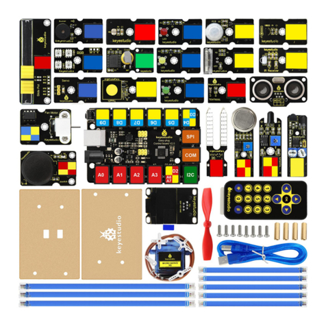
Keyestudio KS0436 Manual

1
WELCOME TO THE
KIT GUIDE
This is your map for navigating beginning embedded electronics.
This kit contains all the information you will need to build the circuit
and robot projects for the keyestudio REV4 Board.
When you’re done with this guide, you will have built five great projects
and acquired the know-how to create countless more.
Now enough talk —let’s start something!
For this guide with more information for each circuit project, visit:
wiki.keyestudio.com

2
Contents
INTRODUCTION............................................................................................ 4
.................................................................... 4
.....................................................................6
.......................................................................8
................................................................................. 11
.......................................................................................16
GET STARTED WITH CIRCUIT PROJECTS!................................................17
Circuit 1: Blinking an LED.................................................................. 18
Circuit 2: Light Extension...................................................................29
Circuit 3: Potentiometer.....................................................................43
Circuit 4: Photo Resistor.................................................................... 55
Circuit 5: Buzzer..................................................................................63
Circuit 6: Button..................................................................................73
Circuit 7: 74HC595 And Segment Display........................................86
Circuit 8: 4-Digit Segment Display.................................................... 99
Circuit 9: LED Matrix Display.......................................................... 118
Circuit 10: LCD “Hello, World!”........................................................126
Circuit 11: Temperature Sensor...................................................... 135
Circuit 12: Temperature and Humidity.......................................... 143
Circuit 13: Flame Sensor..................................................................152

3
Circuit 14: Tilt Ball Switch............................................................... 162
Circuit 15: Vibration Switch............................................................ 170
Circuit 16: Sound Sensor..................................................................176
Circuit 17: Distance Sensor..............................................................186
Circuit 18: Driving Servo Motor...................................................... 198
Circuit 19: Relay................................................................................208
Circuit 20: PIR Motion Sensor......................................................... 216
GET STARTED WITH ROBOT PROJECTS!............................................... 226
ROBOT BASEPALTE ASSEMBLY.......................................................227
Circuit 21: Motor Basics...................................................................233
Circuit 22: Light Following Robot................................................... 248
Circuit 23: Remote-Controlled Robot............................................. 259
Circuit 24: Ultrasonic Ranging Robot............................................. 270
Circuit 25: Object Following Robot.................................................283
GET ALL RESOURCES FOR ROBOT PROJECTS!......................................294

4
INTRODUCTION
The keyestudio REV4 Board is your
development platform.
The REV4 Board is essentially a
small, portable computer, also
known as a microcontroller.
It is capable of taking inputs (such
as the push of a button or a reading from a light sensor) and
interpreting that information to control various outputs (like blinking
an LED light or spinning an electric motor).
This board is capable of taking the world of electronics and relating it
to the physical world in a real and tangible way.
The keyestudio REV4 Board is a microcontroller board based on the
ATmega328P microprocessor.
It has 14 digital input/output pins (of which 6 can be used as PWM
outputs), 6 analog inputs, a 16 MHz quartz crystal, a USB connection, a
power jack, 2 ICSP headers and a reset button.
It contains everything needed to support the microcontroller; simply

5
connect it to a computer with a USB cable or power it via an external
DC power jack (DC 7-12V) or via female headers Vin/GND(DC 7-12V)
to get started.
Hardware Overview:

6
A breadboard is a circuit-building platform that allows you to
connect multiple components without using a soldering iron.
This is a half-size transparent breadboard, good for small projects.
It has 2 power rails on both sides, a standard double-strip in the middle
with 30 columns and 10 rows - a total of 400 tie in points.
This tiny breadboard also has a self-adhesive on the back, so you can
stick it onto an Arduino protoshield or keyestudio chassis.
Breadboard Use:

7

8
Before you can build circuits, you’ll want to first assemble the
breadboard baseplate.
This keyestudio baseplate
makes circuit building easier by
keeping the REV4 Board
microcontroller and the
breadboard connected without
the worry of disconnecting or
damaging your circuit.
1) To begin with, collect your parts: the REV4 Board, breadboard,
screwdriver, keyestudio baseplate and four baseplate screws.

9
2) Align the REV4 board with its spot on the baseplate.
The text on it should face the same direction as the text on the
breadboard and the baseplate.
Using four screws, affix the REV4 Board to the four stand-off holes
found on the baseplate.
3) Peel the adhesive backing off the breadboard.
4) Carefully align the breadboard over its spot on the baseplate. The
text on the breadboard should face the same direction as the text on
the baseplate. Firmly press the breadboard to the baseplate to
adhere it.

10
Your baseplate is now assembled!

11
In order to get your REV4 Board up and running.
you'll need to download the newest version of the Arduino software
from www.arduino.cc (it's free!).
This software, known as the Arduino IDE (Integrated Development
Environment), will allow you to program the REV4 Board to do exactly
what you want. It’s like a word processor for coding.
With an internet-capable computer, open up your favorite browser and
type the following URL into the address bar to download the software
of any versions:
https://www.arduino.cc/en/Main/OldSoftwareReleases#1.5.x
Open Arduino IDE
Downloaded the software package, unzip the folder package, double

12
click the Arduino icon to open.

14
Select Your Board And Serial Port
NOTE: select the Arduino REV4 , but if you are not sure which ports
should choose. Go to your computer panel, and check the Port out in
the Device Manger.

15

16
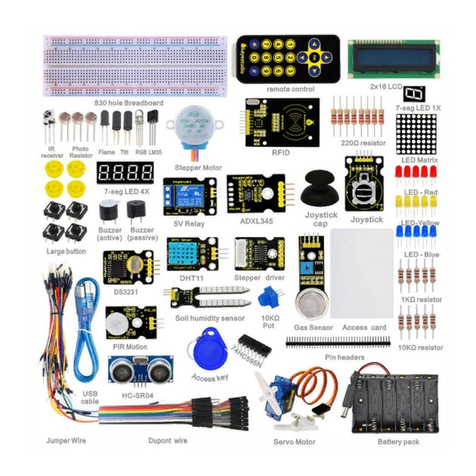
The Kit contains extensive electronic components. Below shows you a
part of kit components:

17
GET STARTED WITH CIRCUIT PROJECTS!
There are 20 circuit projects total. Each project will introduce new
concepts and components, which will be described in more detail as
you progress through the circuits.
As you work your way through each circuit, you will learn to use new
and more complicated parts to accomplish increasingly complex tasks.
The project will set the foundation for the rest and will aid in helping
you understand the fundamentals of circuit building and electricity!

18
Circuit 1: Blinking an LED
About this circuit:
Blinking an LED is the classic starting point for learning how to
program embedded electronic components.
In this circuit, you’ll write code that makes an LED blink on and off.
What You Need:
REV4 Baseplate
Red LED x 1
220ΩResistor x 1
Jumper wires x 2
USB cable x 1
Component Introduction:
LIGHT-EMITTING DIODES (LEDS):
They come in different colors, brightnesses and sizes. LEDs have a

19
positive (+) leg and a negative (-) leg, and they will only let electricity
flow through them in one direction.
LEDs can also burn out if too much electricity flows through them, so
you should always use a resistor to limit the current when you wire an
LED into a circuit.
RESISTORS: resist the flow of electricity.

20
You can use them to protect sensitive components like LEDs. The
strength of a resistor (measured in ohms) is marked on the body of the
resistor using small colored bands.
Each color stands for a number, which you can look up using a resistor
chart.
Table of contents
Other Keyestudio Microcontroller manuals
Popular Microcontroller manuals by other brands

Texas Instruments
Texas Instruments TUSB3210 user guide

STMicroelectronics
STMicroelectronics STM32WL5 Series Reference manual

STMicroelectronics
STMicroelectronics P-NUCLEO-LRWAN2 user manual

Texas Instruments
Texas Instruments AFE4403 user guide

Powercast
Powercast P2110-EVAL-01 user manual

Microsemi
Microsemi IGLOO2 FPGA DSP FIR Filter user guide

Emerson
Emerson Vilter VilTech Operation and service manual

ST
ST STM32F0 Series Application note

CMOSTEK
CMOSTEK CMT2110A user guide

Freescale Semiconductor
Freescale Semiconductor 68HC11 Technician guide

Atmel
Atmel AT43DK325 user guide

Texas Instruments
Texas Instruments Hercules TMS570LS04 Series user guide