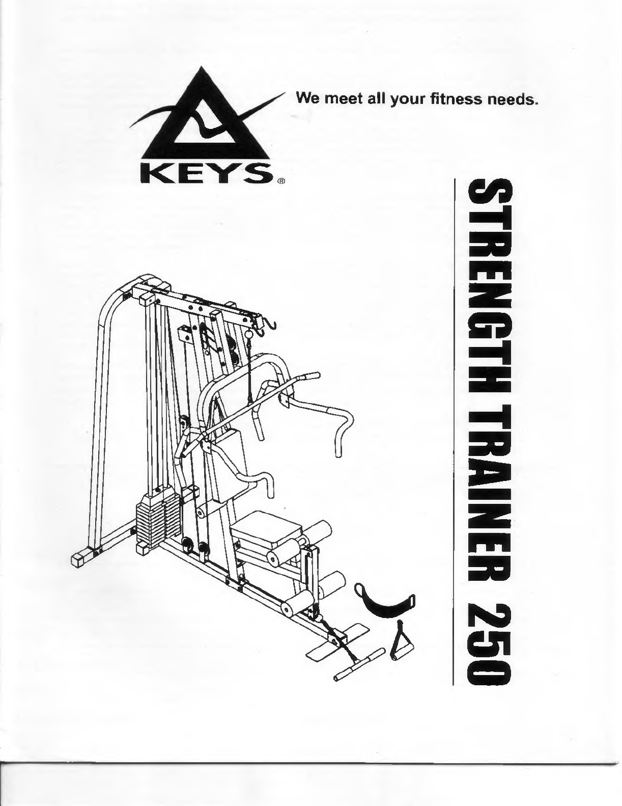
Keysight Technologies STRENGTH TRAINER 250 User manual

yy
dciuic
ucgmuiug
ill
is
ui
any
c\crcisc
piugram
cunsuu
your
puysii'ian.
i
nis
IS
especially
Important
lor
persons
over
the
age
of
35
or
persons
with
pre-existing
health
problems.
Read
all
instructions
in
this
manual
before
using
this
product.
KEYS
FITNESS
assumes
no
responsibility
for
personal
injury
or
property
damage
sustained
by
or
through
the
use
of
this
product.
This
Warranty
applies
only
in
the
United
States
to
products
manufactured
or
distributed
by
Keys
Fitness,
Inc.
under
the
Keys
Fitness
brand
name.
Keys
Fitness
warrants
that
the
Product
you
have
purchased
for
non-commercial,
personal,
family,
or
household
use
from
Keys
fitness
or
from
an
authorized
Keys
Fitness
reseller
is
free
from
defects
in
materials
or
workmanship
under
normal
use
during
the
warranty
period.
Your
sales
receipt,
showing
the
date
of
purchase
of
the
product,
is
your
proof
of
the
date
of
purchase.
This
warranty
extends
only
to
you,
the
original
purchaser.
It
is
not
transferable
to
anyone
who
subsequently
purchases
the
Product
from
you.
It
excludes
expendable
parts.
This
Warranty
becomes
VALID
ONLY
if
the
Product
is
assembled
/
installed
according
to
the
instructions
/
directions
included
with
the
product.
To
obtain
warranty
service,
you
must
return
the
product
and/or
the
defective
part
to
Keys
Fitness
in
its
original
container
(or
equivalent).
You
must
pre-pay
any
shipping
charges,
export
taxes,
customs
duties
and
taxes,
or
any
other
charges
associated
with
transportation
of
the
Product.
In
addition,
you
are
responsible
for
insuring
any
Product
shipped
or
returned.
You
assume
the
risk
of
loss
during
shipment.
You
must
present
Keys
Fitness
with
proof-of-purchase
documents
(including
the
date
of
purchase).
Any
evidence
of
alteration,
erasing
or
forgery
of
proof-of-purchase
documents
will
be
cause
to
void
Warranty.
This
warranty
covers
only
parts,
not
labor
or
receive
charges
for
installation.
This
warranty
does
include
wear
and
tear
on
all
parts.
This
Warranty
does
not
extend
to
any
Product
not
purchased
from
Keys
Fitness
or
from
an
authorized
Keys
Fitness
reseller.
This
warranty
does
not
extend
to
any
Product
that
has
been
damaged
or
rendered
defective;
(a)
as
a
result
of
accident,
misuse,
or
abuse;
(b)
by
the
use
of
parts
not
manufactured
or
sold
by
Keys
Fitness;
(c)
by
modification
of
the
Product;
(d)
as
a
result
of
service
by
anyone
other
than
Keys
Fitness,
or
an
authorized
Keys
Fitness
warranty
service
provider.
Should
any
product
submitted
for
Warranty
service
be
found
to
be
ineligible,
an
estimate
of
repair
cost
will
be
furnished
and
the
repair
will
be
made
if
requested
by
you
upon
Keys
Fitness
receipt
of
payment
or
acceptable
arrangement
of
payment
EXCEPT
AS
EXPRESSLY
SET
FORTH
IN
THE
WARRANTY
KEYS
FITNESS
MAKES
NO
OTHER
WARRANTIES,
EXPRESSED
OR
IMPLIED
INCLUDING
ANY
IMPLIED
WARRANTIES
OF
MERCHANTABILITY
AND
FITNESS
FOR
A
PARTICULAR
PURPOSE.
KEYS
FITNESS
EXPRESSLY
DISCLAIMS
ALL
WARRANTIES
NOT
STATED
IN
THIS
WARRANTY
ANY
IMPLIED
WARRANTIES
THAT
MAY
BE
IMPOSED
BY
LAW
ARE
LIMITED
TO
THE
TERMS
OF
THIS
WARRANTY.
NEITHER
KEYS
FITNESS
NOR
ANY
OF
ITS
AFFILIATES
SHALL
BE
RESPONSIBLE
FOR
INCIDENTAL
OR
CONSEQUENTIAL
DAMAGES.
SOME
STATES
DO
NOT
ALLOW
LIMITATIONS
ON
HOW
LONG
AN
IMPLIED
WARRANTY
LASTS
OF
THE
EXCLUSION
OR
LIMITATION
OF
INCIDENTAL
OR
CONSEQUENTIAL
DAMAGES,
SO
THE
ABOVE
LIMITATIONS
OR
EXCLUSION
MAY
NOT
APPLY
TO
YOU.
This
Warranty
gives
you
express
warranty
applicable
to
Keys
Fitness
branded
products.
Keys
Fitness
neither
assumes
nor
authorizes
anyone
to
assume
for
it
any
other
express
wan-anty.
Before
returning
a
product
you
must
call
Keys
Fitness
at
1-888-340-0482
to
obtain
a
Return
Authorization
Number.
No
returns
will
be
accepted
without
the
Return
Authorization
Number.
Original
purchaser
must
pre-pay
all
freight
charges
on
warranty
claims.
Keys
Fitness
will
not
accept
Freight
Collect
shipments
or
return
shipments
on
freight
collect
basis.
You
must
Fill
outWarranty
Registration
Card
completely,
and
return
it
to
KEYS
FITNESS
within
30
days
of
purchase
for
this
warranty
to
be
valid.
Be
sure
to
include
a
copy
of
your
original
receipt.
PLEASE
FILL
OUT
THE
FOLLOWING
AND
RETURN
TO:
KEYS
FITNESS
PRODUCTS,
L.P.
P.O.
BOX
551239
DALLAS,
TX
75355-1239
NAME_
ADDRESS_
CITY_STATE_ZIP
PHONE(H)_(W)_
ITEM
PURCHASED_STORE
NAME_
PRICE_
WARRANTY
CARD
PURCHASE
DATE
1

IMPORTANT
SAFETY
INFORMATION
WARNING:
Before
beginning
this
or
any
exercise
program
consult
your
physician.
This
is
especially
important
for
persons
over
the
age
of
35
or
persons
with
pre-existing
health
problems.
Read
all
instructions
in
this
manual
before
using
this
product.
KEYS
FITNESS
assumes
no
responsibility
for
personal
injury
or
property
damage
sustained
by
or
through
the
use
of
this
product.
1
Inspect
and
tighten
all
parts
each
time
you
5
Never
release
the
press
arm.
butterfly,
leg
use
the
weight
training
system.
Replace
lever,
bars
or
straps
while
weights
are
any
worn
parts
by
contacting
your
local
raised.
The
weights
will
fall
causing
injury
dealer
or
KEYS
FITNESS.
to
yourself
or
the
weight
system.
2
Keep
your
hands
and
other
parts
of
your
6
Check
cables
to
ensure
they
remain
on
the
body
away
from
moving
parts
other
than
pulleys
as
you
use
the
weight
system,
designed
handles.
7
If
you
feel
pain
or
dizziness
at
any
time
3
Keep
small
children
away
from
the
weight
while
exercising,
stop
immediately
and
system
at
all
times.
begin
cooling
down.
4
When
adjusting
seat
height
make
sure
the
pin
of
the
lock
knob
is
in
one
of
the
holes
in
the
seat
post.
If
the
pin
is
not
in
one
of
the
seat
post
holes,
the
seat
may
slip
during
use
causing
serious
injury.
*
ONLY
TIGHTEN
BOLT
CONNECTIONS
"FINGER
TIGHT"
UNTIL
THE
WEIGHT
SYSTEM
IS
COMPLETELY
ASSEMBLED
UNLESS
OTHER
WISE
TOLD
TO
DO
SO
IN
INSTRUCTIONS.
*
Assembly
requires
two
persons.
*
The
following
tools
(not
included)
are
required
for
assembly
the
Strength
Trainer
250:
two
8"
adjustable
wrenches,
a
9/16"
socket
wrench,
a
1/2"
socket
wrench,
a
rubber
mallet,
and
a
standard
screwdriver.
*
Read
each
step
in
alphabetical
order
completely
before
proceeding.
Do
not
skip
ahead,
it
may
result
in
mis-assembly
which
may
damage
the
weight
system.
*
Place
all
parts
of
the
ST
250
in
a
cleared
area
and
remove
the
paccking
material.
Do
not
dispose
of
the
Packing
materials
until
assembly
is
completely.

PARTS
LIST
^GRAM#
PART
NAME
1
Main
Base
Frame
2
Rear
Stabilizer
3
Rear
Upright
4
Foot
Plate
5
Front
Upright
6
Flat
Plate
7
Top
Frame
8
Seat
Support
9
Seat
Brace
10
Leg
Extension
Tube
11
Press
Arm
12
Rear
Bar
13
Press
Bar
14
Bracket
of
Press
Arm
15
Chroming
Tube
16
Flat
Plate
17
Adj.
Plate
18
Seat
/
Back
Cushion
19
Pad
Tube
20
Lat
Bar
21
Curl
Bar
22
Metal
Spacer
23
Metal
Spacer
24
Metal
Spacer
25
Selecting
Rod
26
Pivot
Bolt
27
Cable
Resistance
Plate
28
Pad
Tube
29
Hex
Head,
Bolt
30
Hex
Head,
Bolt
31
Hex
Head,
Bolt
32
Hex
Head,
Bolt
33
Hex
Head,
Bolt
Q'TY
1
1
2
1
1
t3.0x
50x
130
2
1
1
1
1
1
2
2
2
2
t3.0
x
50
x
200
1
t3.0
x
235
x
50
2
t12x
395x250
2
25.4
x
t
1.5x
440
3
25.4
x
t
2.0x
1150
1
25.4
x
t
2.0x
400
1
15.8x10x20
4
12.7
x
tl.5
x
12
12
12.7
xt1.5x
9.5
3
25.4x475
1
1/2"
x
19.1
x
210
1
t3.0
x
20
x
84
1
0
3/8"
x
2
5/8
7
3/8"
x
2
3/4"
5
3/8"
x
3"
13
3/8"
x
3
1/2"
2
3/8"
x
4"
3
3

PARTS
LIST
DIAGRAM#
PART
NAME
Q’TY
34
Hex
Head
Bolt
3/8"
x
7
3/8"
2
35
Hex
Head
Bolt
3/8"
x
2
3/8"
2
36
Hex
Head
Bolt
3/8"
x
1
7/8"
4
37
Hex
Head
Bolt
3/8"
x
3
3/4"
1
38
Washer
3/8"
x
23
x
t
2.0
78
39
Washer
1/2"
x
28
x
t
2.0
2
40
Nylon
Nut
3/8"
37
41
Hex
Head
Bolt
5/16"
x
2
1/2"
2
42
Screw
Bolt
1/4"
x
5/8"
2
43
Nylon
Nut
1/2"
2
44
Nylon
Nut
5/16"
2
45
Washer
5/16"
x
19
xt
2.0
4
46
Eyeball
Pin
3/8"
x
52
2
47
"L"
Pin
3/8"
x
110
1
48
Locking
Knob
3/8"
x
1
5/8"
1
49
Spring
Knob
M20
x
1.5
x
10
1
50
Brass
Bushing
19.3x25.4x31
x
20
2
51
Pulley
90
14
52
long
Handle
Grip
29
x
35
x
140
2
53
Curve
Handle
Grip
29
x
35
x
480
2
54
Hand
Grip
25.4
x
130
4
55
Foam
Roller
22
x
75
x
190
2
56
Foam
Roller
22x110x190
4
57
Round
Plug
25.4
6
58
Square
Plug
45x45
1
59
Square
Plug
50x50
7
60
Plug
50x75
2
61
Round
Plug
31.8
4
62
Square
Plug
38x38
2
63
Square
Cap
50x50
4
64
Metal
Bushing
lOx
16x20x13
2
65
Metal
Bushing
8x12x20x12
4
66
Rubber
Band
12.7
x
6.3
x
130
2
4
PARTS
LIST
VGRAM#
PART
NAME
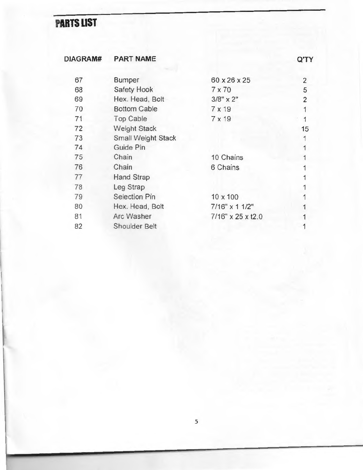
67
Bumper
68
Safety
Hook
69
Hex.
Head,
Bolt
70
Bottom
Cable
71
Top
Cable
72
Weight
Stack
73
Small
Weight
Stack
74
Guide
Pin
75
Chain
76
Chain
77
Hand
Strap
78
Leg
Strap
79
Selection
Pin
80
Hex.
Head,
Bolt
81
Arc
Washer
82
Shoulder
Belt
Q'TY
60
x
26
x
25
2
7x70
5
3/8"
x
2"
2
7x
19
1
7x
19
1
15
1
1
10
Chains
1
6
Chains
1
1
1
10x100
1
7/16"
x
11/2"
1
7/16"
x
25
x
t2.0
1
1
5

Attach
MAIN
BASE
FRAME
(I)
and
FLAT
PLATE
t3.0
x
50
x
50
(6)
to
REAR
STABILIZER
(2)
using.
2-
3/8”
x
3"
BOLTS
4-
3/8”
WASHERS
2-
3/8”
NYLON
NUTS
Tighten
BOLTS
firmly.
|
B]
Attach
FRONT
UPRIGHT
(5)
to
MAIN
BASE
FRAME
(1)
using.
2-
3/8"
x
3"
BOLTS
4-
3/8"
WASHERS
2-
3/8"
NYLON
NUTS.
AND
SCREW
THE
RUBBER
STOP
BUMPER
(48)
into
the
thread
of
the
FRONT
UPRIGHT
(5)
(as
shown)
in
drawing.
Attach
one
REAR
UPRIGHT
(3)
to
each
side
to
REAR
STABILIZER
(2)
USING.
4-
3/8”
x
3"
BOLTS
8-
3/8"
WASHERS
4-
3/8"
NYLON
NUTS.
Attach
FOOT
PLATE
(4)
to
MAIN
BASE
FRAME
(1)
and
insert
L"
PIN
(47)
into
the
hole
of
the
FOOT
PLATE
(4)
and
MAIN
BASE
FRAME
(I).
Press
SQUARE
PLUG
(59)
into
the
end
of
the
MAIN
BASE
FRAME
(1)
and
press
four
2”
SQUARE
CAPS
(63)
onto
the
MAIN
BASE
FRAME
(1)
and
REAR
STABILIZER
(2)
(as
shown)
in
drawing.

Slide
one
ROUND
BUMPER
(67)
onto
each
CHROME
TUBE
(15).
Insert
two
CHROME
TUBES
(15)
into
hole
of
the
MAIN
BASE
FRAME
(1).
Slide
15
WEIGHT
STACK
PLATES
(72)
and
GUIDE
PIN
(74)
onto
CHROME
TUBE
(15)
into
hole
of
the
TOP
FRAME
(7)
and
screw
tight
using
2-
1/4"
x
5/8"
SCREW
BOLT.
Attach
FRONT
UPRIGHT
(5)
to
TOP
FRAME
(7)
using.
1-3/8"x33/4"BOLT
1-
3
/8"
x
2
3/4"
BOLT
4-
3/8"
WASHERS
2-
3/8"
NYLON
NUT.
Attach
TOP
FRAME
(7)
and
3
x
50
x
200
FLAT
PLATE
(16)
to
REAR
UPRIGHT
(3)
using,
4-
3/8"
x
3"
BOLT
8-
3/8"
WASHERS
4-
3/8"
NYLON
NUT.
Press
two
BRASS
BUSHINGS
(50)
into
hole
of
the
TOP
FRAME
(7).
Press
50
x
75
PLUG
(60),
and
two
50
x
50
SUQARE
PLUGS
(59)
into
each
end
of
the
TOP
FRAME
(7)
(as
shown).
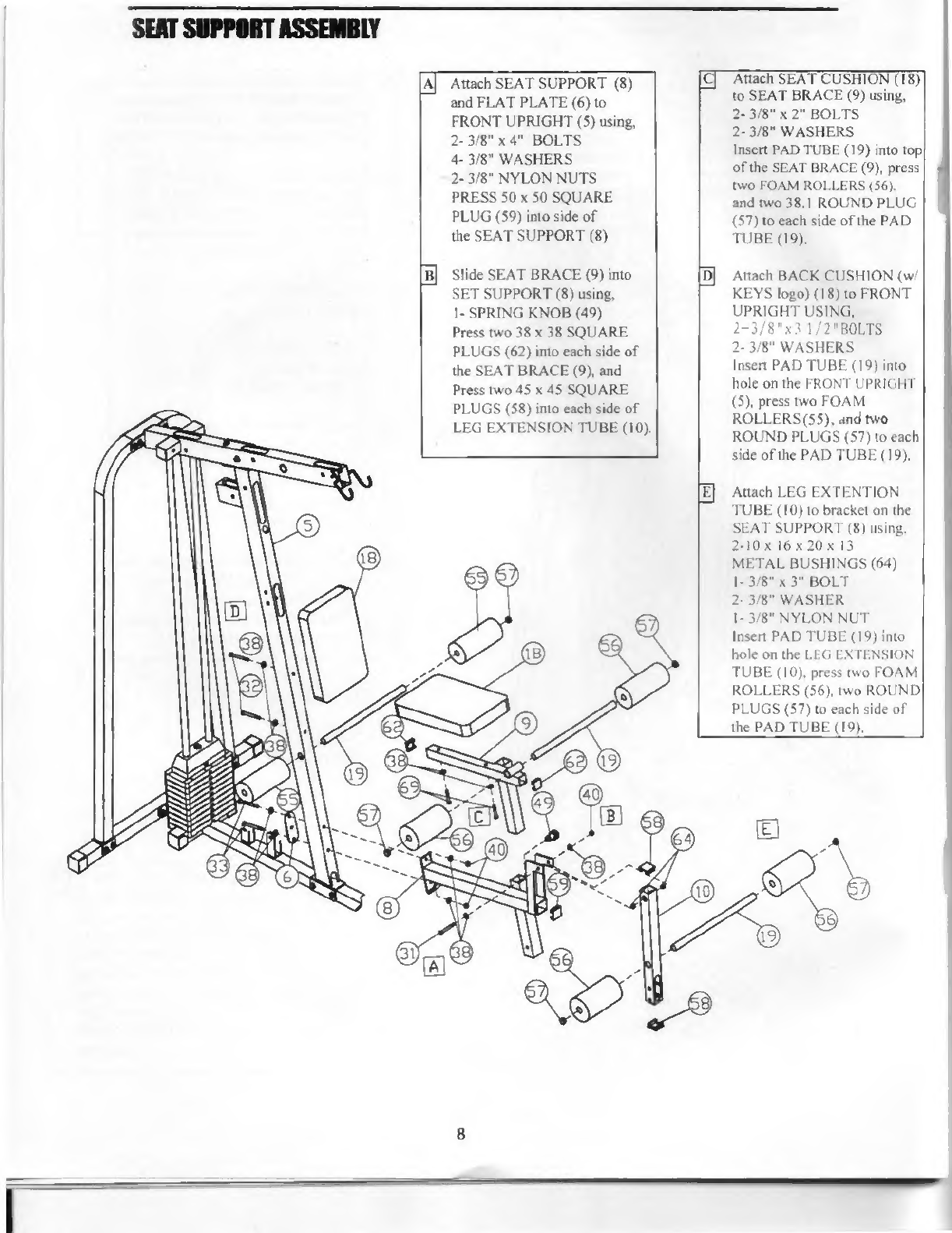
Attach
SEAT
SUPPORT
(8)
and
FLAT
PLATE
(6)
to
FRONT
UPRIGHT
(5)
using,
2-3/8”
x
4"
BOLTS
4-
3/8"
WASHERS
2-
3/8"
NYLON
NUTS
PRESS
50
x
50
SQUARE
PLUG
(59)
into
side
of
the
SEAT
SUPPORT
(8)
Slide
SEAT
BRACE
(9)
into
SET
SUPPORT
(8)
using,
1-SPRING
KNOB
(49)
Press
two
38
x
38
SQUARE
PLUGS
(62)
into
each
side
of
the
SEAT
BRACE
(9),
and
Press
two
45
x 45
SQUARE
PLUGS
(58)
into
each
side
of
LEG
EXTENSION
TUBE
(10).
Attach
SEAT
CUSHION
(18)
to
SEAT
BRACE
(9)
using,
2-
3/8"
x
2"
BOLTS
2-
3/8"
WASHERS
Insert
PAD
TUBE
(19)
into
top
of
the
SEAT
BRACE
(9),
press
two
FOAM
ROLLERS
(56).
and
two
38.1
ROUND
PLUG
(57)
to
each
side
of
the
PAD
TUBE
(19).
Attach
BACK
CUSHION
(w/
KEYS
logo)
(18)
to
FRONT
UPRIGHT
USING,
2-3/8"x31/2"BOLTS
2-
3/8"
WASHERS
Insen
PAD
TUBE
(19)
into
hole
on
the
FRONT
UPRIGHT
(5),
press
two
FOAM
ROLLERS
(55),
and
two
ROUND
PLUGS
(57)
to
each
side
of
the
PAD
TUBE
(19).
Attach
LEG
EXTENTION
TUBE
(10)
to
bracket
on
the
SEAT
SUPPORT
(8)
using.
2-10
x
16
x
20
x
13
METAL
BUSHINGS
(64)
1-
3
/8"
x
3"
BOLT
2-
3/8"
WASHER
I-3/8"
NYLON
NUT
Insert
PAD
TUBE
(19)
into
hole
on
the
LEG
EXTENSION
TUBE
(10),
press
two
FOAM
ROLLERS
(56).
two
ROUND
PLUGS
(57)
to
each
side
of
the
PAD
TUBE
(19).
m
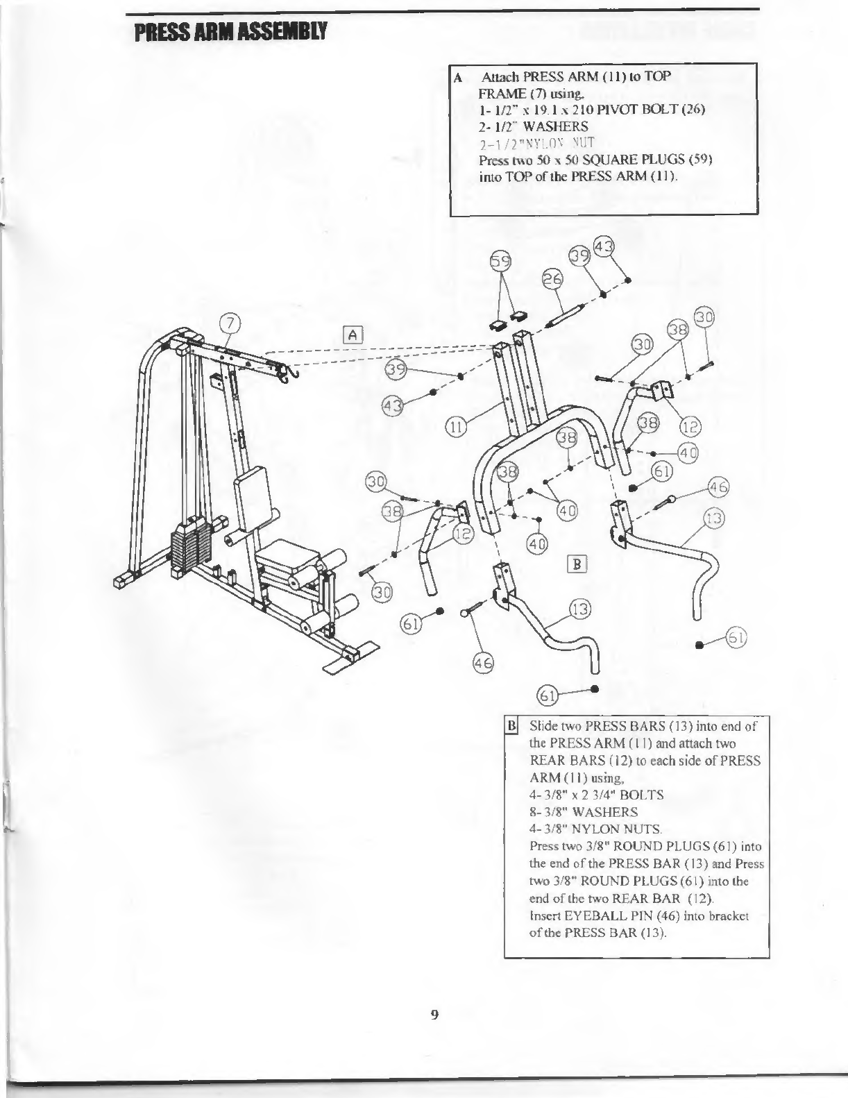
Attach
PRESS
ARM
(11)
to
TOP
FRAME
(7)
using.
1-
1/2"
x
19.1
x
210
PIVOT
BOLT
(26)
2-
1/2"
WASHERS
2-1/2"NYLON
NUT
Press
two
50
x
50
SQUARE
PLUGS
(59)
into
TOP
of
the
PRESS
ARM
(II)
i
Slide
two
PRESS
BARS
(13)
into
end
of
the
PRESS
ARM
(11)
and
attach
two
REAR
BARS
(12)
to
each
side
of
PRESS
ARM
(II)
using,
4-
3/8"
x
2
3/4"
BOLTS
8-
3/8"
WASHERS
4-
3/8"
NYLON
NUTS.
Press
two
3/8"
ROUND
PLUGS
(61)
into
the
end
of
the
PRESS
B
AR
(13)
and
Press
two
3/8"
ROUND
PLUGS
(61)
into
the
end
of
the
two
REAR
BAR
(12).
Insert
EYEBALL
PIN
(46)
into
bracket
of
the
PRESS
BAR
(13).

IT
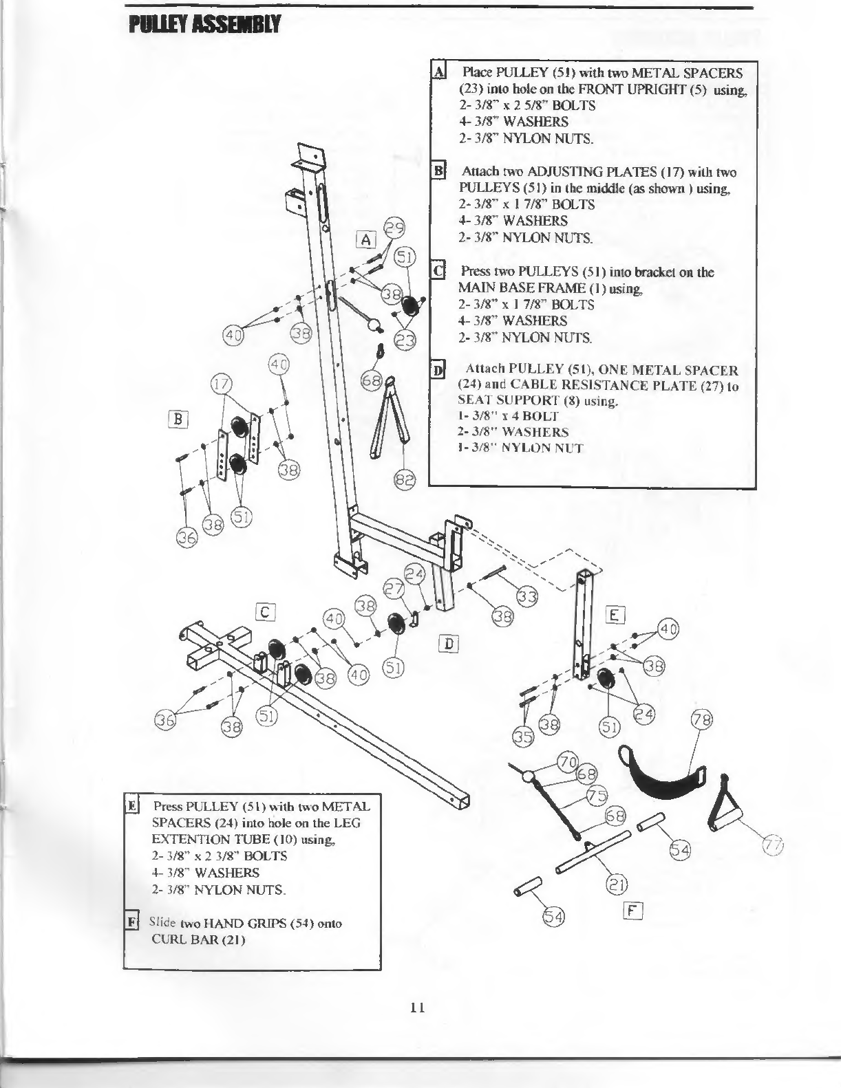
Place
PULLEY
(51)
with
two
METAL
SPACERS
(23)
into
hole
on
the
FRONT
UPRIGHT
(5)
using,
2-
3/8"
x
2
5/8"
BOLTS
4-
3/8"
WASHERS
2-
3/8"
NYLON
NUTS.
Attach
two
ADJUSTING
PLATES
(17)
with
two
PULLEYS
(51)
in
the
middle
(as
shown
)
using
2-
3/8"
x
1
7/8"
BOLTS
4-
3/8"
WASHERS
2-
3/8"
NYLON
NUTS.
Press
two
PULLEYS
(51)
into
bracket
on
the
MAIN
BASE
FRAME
(I)
using
2-
3/8”
x
1
7/8"
BOLTS
4-
3/8"
WASHERS
2-
3/8"
NYLON
NUTS.
Attach
PULLEY
(51),
ONE
METAL
SPACER
(24)
and
CABLE
RESISTANCE
PLATE
(27)
to
SEAT
SUPPORT
(8)
using.
1-
3
/8”
x
4
BOLT
2-
3/8”
WASHERS
1-3/8”
NYLON
NUT
1(J
Press
PULLEY
(51)
with
two
METAL
SPACERS
(24)
into
hole
on
the
LEG
EXTENTION
TUBE
(10)
using
2-
3/8"
x
2
3/8"
BOLTS
4-
3/8"
WASHERS
2-
3/8”
NYLON
NUTS.
Slide
two
HAND
GRIPS
(54)
onto
CURL
BAR
(21)
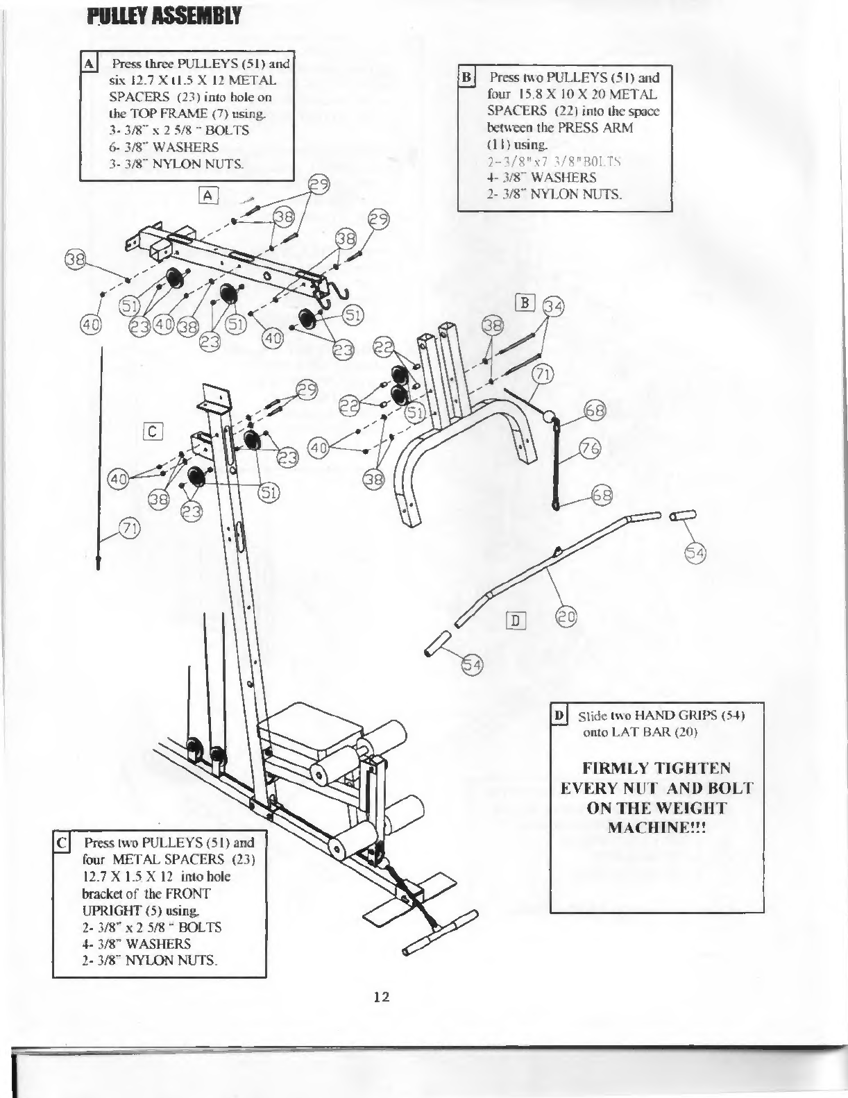
Press
three
PULLEYS
(51)
and
six
12.7Xtl.5X
12
METAL
SPACERS
(23)
into
hole
on
the
TOP
FRAME
(7)
using.
3-
3/8"
x
2
5/8
•
BOLTS
6-
3/8"
WASHERS
3-
3/8"
NYLON
NUTS.
Press
two
PULLEYS
(51)
and
four
15.8
X
10X20
METAL
SPACERS
(22)
into
the
space
between
the
PRESS
ARM
(II)
using.
2-3/8"x7
3/8"BOLTS
4-
3/8"
WASHERS
2-
3/8"
NYLON
NUTS
It!
Slide
two
HAND
GRIPS
(54)
onto
LAT
BAR
(20)
Press
two
PULLEYS
(51)
and
four
METAL
SPACERS
(23)
12.7
X
1.5
X
12
into
hole
bracket
of
Ihe
FRONT
UPRIGHT
(5)
using
2-
3/8"
x
2
5/8
"
BOLTS
4-
3/8"
WASHERS
2-
3/8”
NYLON
NUTS
FIRMLY
TIGHTEN
EVERY
NUT
AND
BOLT
ON
THE
WEIGHT
MACHINE!!!
12
Table of contents
Popular Fitness Equipment manuals by other brands


G-FITNESS
G-FITNESS AIR ROWER user manual

CAPITAL SPORTS
CAPITAL SPORTS Dominate Edition 10028796 manual

Martin System
Martin System TT4FK user guide

CIRCLE FITNESS
CIRCLE FITNESS E7 owner's manual

G-FITNESS
G-FITNESS TZ-6017 user manual

Accelerated Care Plus
Accelerated Care Plus OMNISTIM FX2 CYCLE/WALK user manual


