KICK ASS KA1224MPPT20A User manual

Maximum Power Point Tracking (MPPT)
KA1224MPPT20A
20A
12V/24V
40A
KA1224MPPT40A
100V(25℃),90V(-25℃)
User Manual
KA1224MPPT20A - KA1224MPPT40A
Solar Charge Controller
Model
Battery voltage
Max. solar panel voltage
Charging current
Version: 1.03 The above information is subject to change without prior notice.

ŸThis product is designed to monitor a solar panel's generated power, tracking the
highest voltage and current values in real time. This allows the charging of your
battery to its highest potential, enabling the maximum power output.
ŸCan be used on all types of solar panels.
ŸThe product features an easy to read LCD display allowing you to check and adjust
parameters by using the direction keys below the screen. This also allows you to
modify your controller to best suit your system.
ŸWith built-in diagnostics technology, the controller is able to identify faults and
display error codes for ease of troubleshooting.
1. PRODUCT INTRODUCTION
①
②
③
④
⑤
⑥
⑦
⑧
⑨
⑩
⑪
⑫
⑬
⑭
⑮
⑦
①
②
③
④
⑤
⑥
⑧ ⑨ ⑩⑪ ⑫ ⑬⑭ ⑮
Battery "+" interface
Battery "-" interface
Load "+" interface
Load "-" interface
External temperature sampling interface
RJ12 communication interface
Fig. 1-1 Product appearance and interfaces
Charging indicator
Battery indicator
Load indicator
Abnormality indicator
LCD screen
Operating keys
Installation hole
Solar panel "+" interface
Solar panel "-" interface
No. No. Item
Item
1.1 Exterior Interface

2. INSTALLING CONTROLLER
ML2420 20A 20A 5mm2
5mm 2
ML2440 40A 20A 5mm 2
10 mm2
Model Rated charging
current Rated discharging
current Battery wire
diameter (mm2) Load wire
diameter (mm2)
≥150mm
≥150mm
Hot air
Cold air
Fig. 2.1 Installation and heat dissipation
ŸTake care when installing lead acid batteries, always wear correct safety equipment.
ŸKeep terminals protected from foreign metal objects to ensure terminals don’t short.
ŸMake sure battery is sufficiently ventilated.
ŸKeep battery away from open flames.
ŸMake sure battery is protected from direct sunlight and rain/water intrusion.
ŸLoose connections or corrosion to the terminals can cause excessive heat which may
melt wiring.
ŸAlways use insulated tools and keep hands dry when carrying out installation.
ŸAlways follow the safety advice given by the battery manufacturer.
ŸConnect the controllers earth terminal to ground.
Wiring installation must comply with with national and local electrical specifications.
The wiring specifications of the battery and loads must be selected correctly to the size of
the maximum output current.
See table below for correct wiring specifications:
Risk of explosion! Never install the
controller and battery together in
a sealed environment where
battery gas may accumulate.
Solar panels connected in series
can produce a high voltage.
Always disconnect battery whilst
connecting any wiring to
controller.
When installing controller, make
sure it is in a well ventilated area
(see fig 2.1)
!
2.1 Wiring Specifications
2.2 Installation and Wiring

3. PRODUCT OPERATION AND DISPLAY
CHOOSING AN INSTALLATION SITE
Keep controller away from direct sunlight or high temperatures.
This will ensure that you get the maximum efficiency from your controller.
Make sure area is well ventilated and away from any moisture.
MOUNTING THE CONTROLLER
Using the template provided,mark 4 holes on flat surface area intended for
controller. Screw into flat surface and line up mounting holes on controller and hang
controller.
BEFORE OPERATION
Make sure all connections are tight, secure and that all fuses and circuit breakers are ok.
If the LCD screen fails to turn on, remove fuse from battery and check that all
connections have been made correctly.
Once LCD screen turns on manually test that the load is switching on and off.
When controller is charging, always disconnect the load before disconnecting your
battery. This will save your controller from any possible damage.
Within 10 minutes after the controller stops charging, reversely connecting battery
will result in damage to the controller.
Never connect an inverter, fridge, or other accessory requiring consistent, reliable
power directly to the load side of the controller. Always connect your inverter and
accessories directly to your battery, fused appropriately.

①
②
③
④
⑤
⑥
PV array indicator:
BAT indicator:
LOAD indicator:
3.1 LED Indicators
PV array indicator
BAT indicator
LOAD indicator
ERROR indicator
Indicating the controller's current charging mode.
Indicating the battery's current state.
Indicating the load's On/ Off and state.
Indicating whether the controller is functioning normally.
Steady on
Slow flashing
(a cycle of 2s with on and off each lasting for 1s)
Single flashing
(a cycle of 2s with on and off lasting respectively for
0.1s and 1.9s)
Quick flashing
(a cycle of 0.2s with on and off each lasting for 0.1s)
Double flashing
(a cycle of 2s with on for 0.1s, off for 0.1s, on again
for 0.1s, and off again for 1.7s)
Off
MPPT charging
Boost charging
Floating charging
Equalizing charging
Current-limited
charging
No charging
No. Indicator state Charging state
Graph
Indicator state
Steady on
Slow flashing (a cycle of 2s with on and off each lasting for 1s)
Quick flashing
(a cycle of 0.2s with on and off each lasting for 0.1s)
Battery state
Normal battery voltage
Battery over-discharged
Battery over-voltage
Indicator state
Off
Quick flashing (a cycle of 0.2s with on and off each lasting for 0.1s)
Steady on
Battery state
Load turned off
Load overloaded/ short-circuited
Load functioning normally
ERROR indicator:
Indicator state
Off
Steady on
Battery state
System operating normally
System malfunctioning

3.2 Key Operations
Up
Down
Return
Set
Page up; increase the parameter value in setting
Page down; decrease the parameter value in setting
Return to previous menu (exit without saving)
Enter into sub-menu; set/save; Turn
on/off loads (in manual mode)
3.3 LCD Startup and Main Interface
Nighttime Daytime Solar panel Charging
Battery
Discharging Load
Parameter value
Unit
Battery type
AbnormalityBluetoothSerial
port
Setting
System
voltage
Charging
stage
During startup, the 4 indicators will first flash successively, and after self-inspection, the LCD
screen starts and displays the battery's voltage level which will be either a fixed voltage
selected by the user or a voltage automatically recognized.
3.3.1 Startup interface

3.3.2 Main interface
Main monitoring page
Charging current
Battery voltage
Load current
Charging capacity
Discharging capacity
Device temperature
Load mode
Abnormality code
Component voltage

NO. MODE DESCRIPTION
0Solar Controlled
(Switched based on
solar state)
5 minutes after sunlight is no longer
present, the load will be switched on.
The load will remain on until 1 minute
after sunlight returns.
1-14 Solar Controlled +
Duration
(Switched based on
solar state and
mode 1-14)
5 minutes after sunlight is no longer
present, the load will be switched on.
The load will then remain on for a period
of hours specified by the mode number
- ie. mode 2 = 2 hours, before switching
off.
15 Manual Mode Load output is switched manually
using arrow keys on controller.
17 Constant Power
Mode
Load output remains powered on
continuously.
3.4.2 LOAD MODE ADJUSTMENT
Press the set key until the load mode screen appears,then press and hold the set key to
enter press the up and down key to desired setting then press and hold the set key to save
and exit.
Load mode Press and hold the
Set key to enter Tap the Up or
Down key to set the mode Press and hold the
Set key to save and exit
Tap the Return
key to exit
without saving
3.4 Load Mode Setting Interface
3.4.1 Load modes introduction
This controller has 5 load operating modes which will be described below:
UP DOWN RETURN SET

4. PRODUCT PROTECTION AND MAINTENANCE
Waterproof
Waterproof level: IP32
Battery reverse polarity protection
If the battery is connected in reverse the controller will not turn on, as to protect the
controller from component damage.
Solar input high voltage protection
If the solar panel array voltage is too high, the controller will automatically shut down.
Solar input short circuit protection
If the solar panel has a short circuit, the controller will stop working until the short is rectified.
The controller will then start working normally again.
Solar panel reverse polarity protection
If the solar panel is reversely connected, the controller will stay illuminated however there will
be no power fed to the battery The controller will return to normal operation once the wiring
has been corrected.
Load overpower protection
When the load power exceeds the rated power value, the load will enter into delay protection.
Load short circuit protection
If the load is short circuited, the controller will protect the load by shutting it down this can
happen 5 times per day without affecting the controller.
Reverse charging protection at night
This function will protect the battery from discharging through the solar panel at night.
Over temperature protection
15%
20%
25%
35%
40%
45%
55%
60%
65%
75%
80%
85%
95%
100%
Chg-P :/%
66
Tem-MOS :/ ℃
65 67 68 69 70 71 72 73 74 75 76 77 78 790
0
5 % Fig. 4-1

4.1 System Maintenance
To maintain the controller's performance it is recommended that the
following maintenance be carried out.
ŸMake sure there is enough air flow around and behind controller
ŸEnsure cooling fins are free of dirt or debris.
ŸCheck for any exposed wiring between solar panel and battery and also check the load
if applicable.
ŸCheck that indicators are working correctly and check for fault codes in data analysis
page, repair faults if recorded
ŸCheck all terminal screws are tight and that there is no corrosion on terminals and
wiring
ŸIf the lightning arrestor has lost its efficiency replace with a new one in a timely manner.
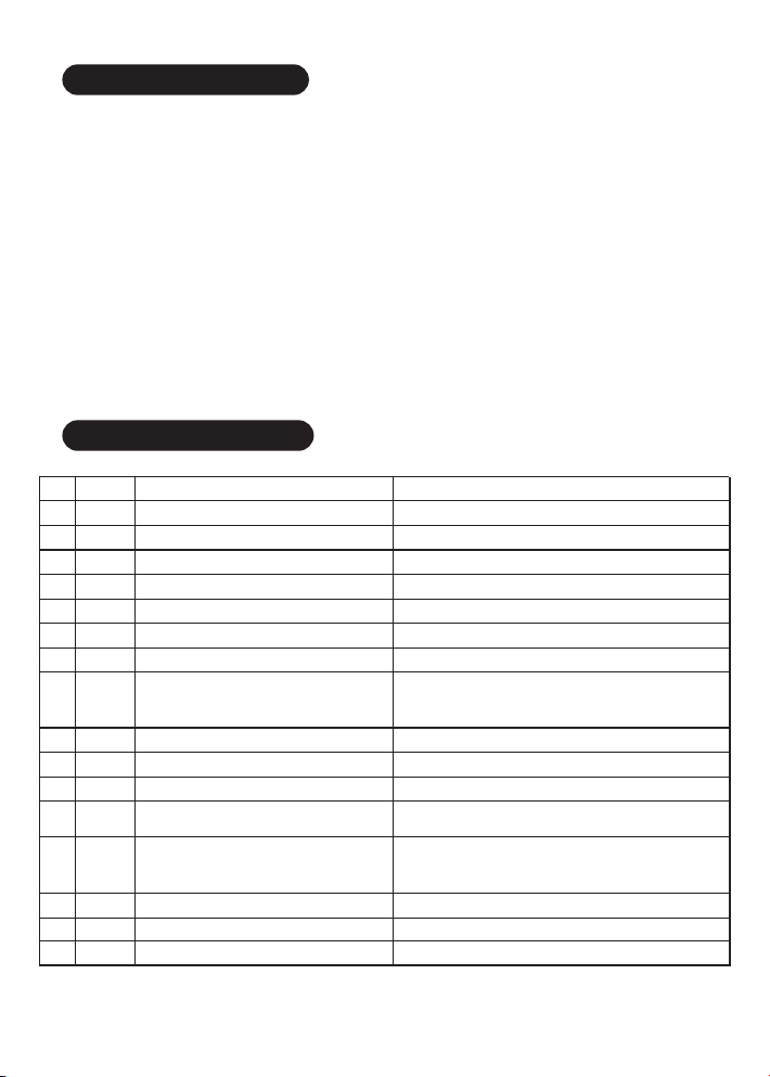
4.2 Abnormality Display
No. Error
display Description LED indication
1
2
3
4
5
6
7
9
11
12
EO
E1
E2
E3
E4
E5
E6
E8
E10
E13
No abnormality
Battery over-discharge
Battery over-voltage
Battery under-voltage warning
Load short circuit
Load overloaded
Over-temperature inside controller
Solar array overloaded
Solar array over-voltage
Solar array reverse polarity
ERROR indicator off
BAT indicator flashing slowly ERROR indicator steady on
BAT indicator flashing quickly ERROR indicator steady on
ERROR indicator steady on
LOAD indicator flashing quickly ERROR indicator steady on
ERROR indicator steady on
8E7 Battery over temperature (E7 and E16 are
different in that charging and discharging
have separate upper limit protection
temperature)
ERROR indicator steady on
13 E15 Battery not connected or lithium battery
feed protection ERROR indicator steady on
14 E16 Battery over temperature (E7 and E16 are
different in that charging and discharging
have separate upper limit protection
temperature)
ERROR indicator steady on
16 E17 Over-temperature inside controller ERROR indicator steady on
17 E20 Battery reverse polarity ERROR indicator steady on
15 E18 BMS over-current protection ERROR indicator steady on

5.1 Electric Parameters
Value
KA1224MPPT20A
12V/24VAuto
0.7 W to 1.2W
9V to 35V
100V(25℃)90V(-25℃)
Battery Voltage+2V to 75V
20A
20A
10000uF
260W/12V
520W/24V
≤98%
>99%
-3mv/℃/2V(default)
-35℃ to +45℃
IP32
RJ12
≤ 3000m
210*151*59.5mm
KA1224MPPT40A
40A
1040W/24V
238*173*72.5mm
1.4Kg 2Kg
Parameter
Model
System voltage
No-load loss
Battery voltage
Max. solar input voltage
Max. power point voltage
range
Rated charging current
Rated load current
Max. capacitive load
capacity
Max. photovoltaic system
input power
Conversion efficiency
MPPT tracking efficiency
Temperature
compensation factor
Operating temperature
Protection degree
Weight
Communication method
Altitude
Product dimensions
5. PRODUCT SPECIFICATION PARAMETERS
520W/
12V

16.0V
14.6V
14.4V
13.8V
13.2V
12.6V
12.2V
12.0V
11.1V
10.6V
5s
120 minutes
30 days
120 minutes
16.0V
——
14.2V
13.8V
13.2V
12.6V
12.2V
12.0V
11.1V
10.6V
5s
——
0 days
120 minutes
16.0V
14.8V
14.6V
13.8V
13.2V
12.6V
12.2V
12.0V
11.1V
10.6V
5s
120 minutes
30 days
120minutes
9~17V
9~17V
9~17V
9~17V
9~17V
9~17V
9~17V
9~17V
9~17V
9~17V
1~30s
0~600 minutes
0~250D
10~600 minutes
5.2 Battery Type Default Parameters (parameters set in monitor software)
Parameters cross-reference table for different types of batteries
Sealed lead-acid
battery Gel lead-acid
battery
Open lead-acid
battery User (self-customized)
Voltage to set
Battery type
Over-voltage cut-off
voltage
Equalizing voltage
Boost voltage
Floating charging
voltage
Boost return voltage
Low-voltage cut-off
return voltage
Under-voltage warning
return voltage
Under-voltage warning
voltage
Low-voltage cut-off
voltage
Discharging limit voltage
Over-discharge time
delay
Equalizing charging
duration
Equalizing charging
interval
Boost charging
duration
(0 means the equalizing
charging function is disabled)
When selecting User, the battery type is to be self-customized, and in this case, the default system voltage
parameters are consistent with those of the sealed lead-acid battery. When modifying battery charging
and discharging parameters, the following rule must be followed:
Li Battery
——
——
——
——
——
——
——
——
——
——
14.4V
12.6V
11.1V
PLEASE NOTE: you can access very basic user setup without bluetooth module but to access all will need the module or
remote screen
Over-Voltage
Cut-Off Voltage
Over-Voltage Cut-Off
Return Voltage
Low-Voltage Cut-Off
Return Voltage
Low-Voltage Cut-Off
Voltage
Discharging Limit
Voltage
Under-Voltage Warning
Return Voltage
Under-Voltage
Warning Voltage
Discharging Limit
Voltage
Boost Return
Voltage
Low-Voltage Cut-Off
Return Voltage
Over-Voltage
Cut-Off Voltage
Charging
Limit Voltage
Equalizing
Voltage
Boost
Voltage
Floating Charging
Voltage
Boost Return
Voltage

Conversion efficiency(%)
6.1 12V System Conversion Efficiency
MPPT 12V conversion efficiency (12V battery)
Output power(W)
6.2 24V System Conversion Efficiency
MPPT 24V conversion efficiency (24V battery)
Output power(W)
Conversion efficiency(%)
6. CONVERSION EFFICIENCY CURVE

238
173
180
147
4X 4.5Φ4X 10Φ
6X 8Φ
72.5
72.5
168
123.5
KA1224MPPT40A
Product dimensions:238*173*72.5mm
Hole positions:180*147mm
Hole diameter:Φ3mm
Applicable wire: max. 8 AWG
22
151
210
131
154
59.5
4X 9Φ4X 4.5Φ
8
59.5
6X 7Φ9.3
17
143.6
111
KA1224MPPT20A
Product dimensions:210*151*59.5mm
Hole positions:154*131mm
Hole diameter:Φ3mm
Applicable wire: max. 8 AWG
7. PRODUCT DIMENSIONS
This manual suits for next models
1
Table of contents
Other KICK ASS Controllers manuals
Popular Controllers manuals by other brands

noble pro
noble pro FLYSKY 2.4GHz AFHDS 3 user manual

Gossen MetraWatt
Gossen MetraWatt PROFITEST MF Series operating instructions

Automationdirect.com
Automationdirect.com DirectLOGIC DL205 Series user manual

Carel
Carel FCS Series instructions

Carel
Carel IR32 Series user manual

Kohler
Kohler Decision-Makerr MPAC 1500 manual