manuals.online logo
Brands
  1. Home
  2. •
  3. Brands
  4. •
  5. Kicker
  6. •
  7. Amplifier
  8. •
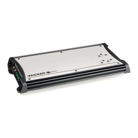
  9. Kicker MX700.5 User manual

Kicker MX700.5 User manual

MX
MULTI-CHANNELMARINE
AMPLIFIER
with a CLASS-DSUBWOOFERCHANNEL
MX700.5
©2007 Stillwater Designs
Installation . . . as easy as 1, 2, 3
1. Mounting Choose astructurally sound locationto mount yourKicker amplifier. Thecontrols onthe
top of theamplifier need to beaccessible foradjustment. Makesure there are no itemsbehind thearea
where thescrews will bedriven. Choose alocationthat allows at least 4” (10cm) of open ventilationfor
theamplifier. Mount theamplifier in alocationfree from directcontactwith water. Drill fourholes using a
7/64” (3mm) bit and use thesupplied #8 screws to mount theamplifier.
2. Wiring Disconnectthevehicle’sbattery to avoid an electrical short. Then connecta4 gauge
grounding wire from theamplifier to thebattery’snegativepost.
Use atwisted pair(s) of RCA interconnectcable to feed theaudio signal to theamplifier. If you are
using only one pair of RCA inputs, connecttheRCA cable to theAMP 1 inputs. Leavetherubber
boots ontheAMP 2and SUB AMP RCA inputs. All fiveMX700.5 channels will work with asingle pair
of RCA inputcable; thefader will notoperate. Keep theRCA cable away from factory wiring harnesses
and other power wiring. If you need to cross this wiring, cross it at a90degree angle.
Install afuse within 18” (45cm) of thebattery and in-line with thepower cable connected to your
amplifier. If you ever need to removetheamplifier from thevehicle after it has been installed, theground
wire should bethelast wire disconnected from theamplifier--just theopposite as when you installed it.
See thebelowforpower and ground wire size, and fusing recommendations.
INSTALLATION
MX.5AMPLIFIER
MX700.5
FiveChannelModel:
MX.5SeriesMarineAmplifier
Owner’sManual
Congratulations on your
KICKER purchase
Please record yourpurchase
informationand keep yoursales
receiptforvalidationof warranty.
Authorized Kicker Dealer:
Purchase Date:
Amplifier Model Number:
Amplifier Serial Number:
__________________________
__________________________
__________________________
__________________________
ModelMX700.5 Fuse90APowerGroundWire 4GA
Note: To get thebest performancefrom yournew Kicker Amplifier, we recommend using genuine Kicker Accessories and Wiring.
Remote
Turn-On
Battery
+12V Fuse
18"
Or Less
(45cm)
Ground
-+
+-+-
Signal In AMP 1
Signal In AMP 2
Left Speaker AMP 1 Right Speaker AMP 1
Minimum impedance of 2 ohms in the Subwoofer Channel
and 2 ohms per channel in stereo operation of the AMPs
Signal In Subwoofer
(Optional)
+-+
Left Speaker AMP 2 Right Speaker AMP 2
-
Mono Speaker
Subwoofer Channel
Remote
Turn-On
Battery
+12V Fuse
18"
Or Less
(45cm)
Ground
+-+-
Right Speaker AMP 1 Left Speaker AMP 2
-+
Signal In AMP 1 (Right)
Signal In AMP 2 (Left)
Minimum impedance of 2 ohms in the Subwoofer Channel
and 2 ohms per channel in stereo operation of the AMPs
Signal In Subwoofer
(Optional)
Mono Speaker
Subwoofer Channel
RCA Y-Adapters
2 3
Figure 2
Figure 3
CONFIGURATION
Figure 1
Sealed Top Panel protects the
controls from water damage.
MX700.5
3. Configuration Thefollowing diagramsshowthemost commonconfigurations foryourKicker MX
series amplifier.
FourChannelOperation with Subwoofer These MX amplifiers are capable of operating into a
minimum impedanceof 2ohmsper channel in stereo operationand 2ohmsmono in thededicated
subwoofer channel. See Figure 2.
BridgedOperation (Mono) TheMX.700.5 series amplifier is capable of operating into aminimum
impedanceof 4 ohmswhen thefourstereo channels are bridged to two mono channels, and 2ohms
mono in thededicated subwoofer channel. This allows you to bridge AMP 1 to runthe“right” sideand
AMP 2to runthe“left” side. You will need two RCA Y-Adapters forthis configuration. AMP 1 and
AMP 2are stable down to 4 ohmsin this mono configuration. See Figure 3.
Operation
You rKicker MX.5 series amplifier has seven rotary controls and two switches onthetop panel. Before turning onthe
system forthefirst time, removethesealed top panel (protects thecontrols from water damage) by removing thetwo
phillipsscrews. See Figure 1. Then turn theseven rotary controls onthetop of theamplifier to thefull counter-
clockwise position.
1. CrossoverSwitch Thecrossover switches onthetop panel are forsetting theinternal crossovers forthe
“full-range” audio channels (12dB slopeper octave). IntheOFF positiontheamplifier passes afull-range signal to the
speakers. TheHI positionshould beselected when connected to speakers, which you do notwant to receiveany
sub-bass information. Never change thecrossover "OFF/HI" switch setting with theaudio system on!
2. InputGainControl Theinputgain controlis notavolumecontrol. Itmatches theoutputof thesourceunit to the
inputlevel of theamplifier. Turn thesourceunit up to about3/4 volume(if thesourceunit goes to 30, turn it to 25).
Next, slowly turn (clockwise) thegain ontheamplifier up until you can hear audible distortion, then turn it down alittle.
Adjust AMP 1, then proceed to AMP 2and finally theSubwoofer Channel inputgain control.
3. BassBoostControl Thebass boost controlis designed to giveyou increased output0- 18dB at 40Hz. The
setting forthis controlis subjective. If you turn it up, you must go back and adjust theinputgain controlto avoid
clipping theamplifier.
4. CrossoverControl Thesetting forthis controlis subjective; 80Hz is agood placeto start.
5. RemoteBass(Level Control) When using theremote bass level controlyou havetheability to controlthelevel of
theSubwoofer Channel’soutputremotely. To mount theremote bass level control, simply screw themetal bracket to
thechosen location. Then slidethehousing onto thebracket until it snapsinto place. Runthecable from thecontroller
to the“Remote Bass” jack ontheamplifier chassis.
LED Red, no output? 1) Amplifier is very hot. Thermal protectionis engaged. Test forproper impedanceat the
speaker terminals with aVOM meter (see thediagramsin this manual forminimum recommended impedanceand
multiple speaker wiring suggestions). Also check foradequate airflowaround theamplifier. 2) Amplifier shuts down
only while vehicle is running. Voltage protectioncircuitry is engaged. Voltage to theamplifier is notwithin the9-16
volt operating range. Havethevehicle'scharging and electrical system inspected. 3) Amplifier will only play at low
volumelevels. Short circuit protectionis engaged. Check forspeaker wires shorted to each other orto thevehicle
chassis. Check fordamaged speakers, orspeaker(s) operating belowtheminimum recommended impedance.
No output from one channel? 1) Check thebalancecontrolonsourceunit 2) Check theRCA and speaker
outputconnections forthechannel 3) Swap theRCA cable from leftto right. If the problem changes sides then you
have a bad RCA cable or source unit problem. 4) Swap thespeaker outputwire from leftto right. If the problem
changes sides then you have a bad speaker cable, passive crossover network and/or speaker.
Alternator noise-whining sound with engine’s RPM? 1) Check fordamaged RCA (orspeaker input) cable
2) Check therouting of RCA (orspeaker input) cable 3) Check thesourceunit forproper grounding 4) Check the
gain settings and turn them down if they are set too high.
Poor stereo image or reduced bass response? Check system phasing by turning thebalancecontrolfrom left
to right. If there is more bass outputwhen turned to either side, then check yourspeaker wiring, passivecrossover
networksand speaker terminals forproper positiveand negativeconnections. Reverse aspeaker connectionfrom
positiveto negativeonthestereo/subwoofer channel(s); if thebass improves, thespeaker was outof phase.
Ground-Loop Noise? If you are using only one pair of RCA inputs, connecttheRCA cable to theAMP 1 inputs.
No Fader? You must use both sets of RCA Inputs forAMP 1 and 2, in order forthesource’sfader to work.
If you havemore questions abouttheinstallationoroperationof yournew KICKER product, see theAuthorized KICKER Dealer where you
madeyourpurchase. Formore adviceoninstallation, click ontheSUPPORT tab ontheKicker homepage, www.kicker.com. Choose the
TECHNICAL SUPPORT tab, choose thesubjectyou are interested in, and then download orview thecorresponding information.
Please E-mail support@kicker.com orcall Technical Services (405) 624-8583 forunanswered orspecific questions.
CAUTION: When jump starting thevehicle, besure that connections madewith jumper cables are correct. Improper connections can
result in blown amplifier fuses as well as thefailure of other critical systemsin thevehicle.
Performance
Model MX700.5
RMSPower in Watts, AMP 1 and AMP 2channels driven
@14.4V, 4ΩStereo ≤1% THD+N 70 x 4
@14.4V, 2ΩStereo, ≤1% THD+N 85 x 4
@14.4V, 4ΩMono, ≤1% THD+N 165 x 2
RMSPower in Watts, Subwoofer Channel driven
@14.4V, 4ΩMono, ≤1% THD+N 210x 1
@14.4V, 2ΩMono, ≤1% THD+N 420 x 1
Length: 20” (507mm)
Height: 23/8” (60mm)
Width: 10” (254mm)
Frequency Response, ± 0.5 dB: 20 Hz - 20 kHz
Signal-to-Noise Ratio: >95 dB, a-weighted, re: rated power
InputSensitivity: 125 mV - 5 V
Electronic Crossover: Variable (defeatable) HI pass, 50- 200Hz, 12dB per octave, forthefull-range channels
Variable LOW pass, 50- 200Hz, 24dB per octave, forthesubwoofer channel
Bass Boost: Variable 0to +18 dB boost @ 40Hz, forthesubwoofer channel
MX.5AMPLIFIER
4 5
Model MX700.5
70 x 4, 210 x 1 @ 4 ohms from 20-20K, 20-200Hz, 14.4Vdc,
1% THD, CEA-2006 (Watts)
Signal to Noise Ratio -72 / -55 dBa CEA-2006 (ref: 1W, A-weighted)
PERFORMANCE
OPERATION
All specifications and performancefigures are subjectto change. Please visit thewww.kicker.com forthemost current information.
+
-
+
-
+
-
Figure 4
Two Kicker Coax Speakers wired
in series to a single channel.
Wiring two Kicker Speakers to a single channel
Modern high performancecoaxial and component speakers havealower DC Resistancethan what used to be
available. TheKicker speakers are rated at fourohmsand work with any sourceunit oramplifier designed to operate
at afourohm load. If you want to use two Kicker coax orcomponent speakers oneach channel of youramplifier wire
thespeakers in series, as shown in Figure 4. This will improvethesound quality, lower thetotal harmonic distortion
and lessen thethermal load at thesourceunit oramplifier. This may prevent an amplifier from shutting down, dueto
over-current protectioncircuitry.
TroubleShooting
If youramplifier does notappear to beworking, check theobviousthings first such as blown fuses, poororincorrect
wiring connections, incorrectsetting of crossover switch and gain controls, etc. There is one LEDonthetop of your
Kicker MX series amplifier. When theLEDis green this indicates theamplifier is turned onand no trouble exists. If the
LEDis red, this indicates that theprotectioncircuitry (SORT) is engaged.
LED Green, no output? With aVolt Ohm Meter (VOM) check thefollowing: 1) +12volt power terminal (should
read +12V to +16V) 2) Remote turn-onterminal (should read +12V to +16V) 3) Check forreversed power and
ground connections 4) Ground terminal, forproper conductivity.
LED Green, no output? Check thefollowing: 1) RCA connections 2) Test speaker outputs with a“known” good
speaker. 3) Substitute sourceunit with a“known” good sourceunit. 4) Check forasignal in theRCA cable feeding
theamplifier with the“AC” test positionselected ontheVOM meter.
ElectronicsLimitedWarranty
Kicker warrants this productto befree from defects in material and workmanship under normal use foraperiod of
THREE (3) MONTHSfrom date of original purchase with receipt. When purchased from an Authorized KICKER Dealer
it is warranted forTWO (2) YEARSfrom date of original purchase with receipt. Inall cases you must havetheoriginal
receipt. Should servicebenecessary under this warranty forany reasondueto manufacturing defectormalfunction
during thewarranty period, Kicker will repair orreplace(at its discretion) thedefectivemerchandise with equivalent
merchandise at no charge. Warranty replacements may havecosmetic scratches and blemishes. Discontinued
products may bereplaced with more current equivalent products.
This warranty is valid only fortheoriginal purchaser and is notextended to owners of theproductsubsequent to the
original purchaser. Any applicable implied warranties are limited in durationto aperiod of theexpress warranty as
provided herein beginning with thedate of theoriginal purchase at retail, and no warranties, whether express or
implied, shall apply to this productthereafter. Somestates do notallowlimitations onimplied warranties; therefore
these exclusions may notapply to you. This warranty gives you specific legal rights; however you may haveother
rights that vary from state to state.
WHAT TO DO IF YOU NEED WARRANTY OR SERVICE
Defectivemerchandise should bereturned to yourlocal Authorized Stillwater Designs (Kicker) Dealer forwarranty
service. Assistancein locating an Authorized Dealer can befound at www.kicker.com orby contacting Stillwater
Designs directly. You c an confirm that adealer is authorized by asking to see acurrent authorized dealer window
decal.
If it becomes necessary foryou to return defectivemerchandise directly to Stillwater Designs (Kicker), call theKicker
Customer ServiceDepartment at (405) 624-8510foraReturn Merchandise Authorization(RMA) number. Package all
defectiveitemsin theoriginal container orin apackage that will prevent shipping damage, and return to:
Stillwater Designs, 5021 North Perkins Road, Stillwater, OK 74075
TheRMA number must beclearly marked ontheoutsideof thepackage. Please return only defectivecomponents.
Thereturn of functioning itemsincreases yourreturn freightcharges. Non-defectiveitemswill bereturned freight-
collectto you.
Includeacopy of theoriginal receiptwith thepurchase date clearly visible, and a"proof-of-purchase" statement listing
theCustomer'sname, Dealer'snameand invoicenumber, and productpurchased. Warranty expirationonitems
withoutproof-of-purchase will bedetermined from thetypeof sale and manufacturing date code. Freightmust be
prepaid; itemssent freight-collect, orCOD, will berefused.
WHAT IS NOT COVERED?
This warranty is valid only if theproductis used forthepurpose forwhich it was designed.
Itdoes notcover:
o Damage dueto improper installation
o Subsequent damage to other components
o Damage caused by exposure to moisture, excessiveheat, chemical cleaners, and/orUV radiation
o Damage through negligence, misuse, accident orabuse. Repeated returns forthesamedamage may be
considered abuse
o Any cost orexpense related to theremoval orreinstallationof product
o Speakers damaged dueto amplifier clipping ordistortion
o Itemspreviously repaired ormodified by any unauthorized repair facility
o Return shipping onnon-defectiveitems
o Products with tampered ormissing barcodelabels
o Products returned withoutaReturn Merchandise Authorization(RMA) number
o FreightDamage
o Thecost of shipping productto Kicker
o Serviceperformed by anyone other than Kicker
HOW LONG WILL IT TAKE?
Kicker strives to maintain agoal of 72-hourserviceforall electronics(amplifiers, crossovers, equalizers, etc.) returns.
Delaysmay beincurred if lack of replacement inventory orparts is encountered.
Failure to followthese stepsmay void yourwarranty. Any questions can bedirected to theKicker Customer Service
Department at (405) 624-8510.
InternationalWarranty
ContactyourInternational Kicker dealer ordistributorconcerning specific procedures foryourcountry'swarranty
policies.
WARNING: KICKER products are capable of producing sound levels that can permanently damage yourhearing!
Turning up asystem to alevel that has audible distortionis more damaging to yourears than listening to an
undistorted system at thesamevolumelevel. Thethreshold of pain is alwaysan indicatorthat thesound level is too
loud and may permanently damage yourhearing. Please use commonsense when controlling volume.
GARANTÍA INTERNACIONAL VersiónEspañol
Comuníquese consu concesionario o distribuidorKicker internacional para obtener inforaciónsobre procedimientos
específicosrelacionadosconlas normas degarantíadesu país.
ADVERTENCIA: Losexcitadores Kicker soncapaces deproducir niveles desonido quepueden dañar
permanentemente el oído. Subir el volumen del sistemahasta unnivel queproduzcadistorsiónes másdañino para el
oído queescuchar unsistemasin distorsiónal mismo volumen. Eldolores siempre una indicacióndequeel sonido es
muy fuerte y quepuededañar permanentemente el oído. Sea precavido cuando controle el volumen.
Lafrase "combustible para vivir la vidaLivin' Loud™ atodo volumen" se refiere al entusiasmo porla vidaquela marca
Kicker deestéreosdeautomóvil representa y ala recomendaciónanuestrosclientes dequevivan lo mejorposible ("a
todo volumen") en todo sentido. Lalínea dealtavoces y amplificadores Kicker es la mejordel mercado deaudio de
automóviles y porlo tanto representa el "combustible" para vivir atodo volumen en el área de"estéreosdeautomóvil"
dela vidadenuestrosclientes. Recomendamosatodosnuestrosclientes queobedezcan todas las reglas y
reglamentoslocales sobre ruido en cuanto alosniveles legales y apropiadosdeaudiciónfuera del vehículo.
INTERNATIONALE GARANTIE DeutscheVersion
Nehmen Sie mit Ihren internationalen Kicker-Fachhändler oder Vertrieb Kontaktauf, um Details über die
Garantieleistungen in Ihrem Land zu erfahren.
WARNUNG: KICKER-Treiber können einen Schallpegel erzeugen, der zu permanenten Gehörschäden führen kann!
Wenn Sie ein System auf einen Pegel stellen, der hörbare Verzerrungen erzeugt, schadet das Ihren Ohren mehr, als ein
nichtverzerrtes System auf dem gleichen Lautstärkepegel. Die Schmerzschwelle ist immer eine Anzeige dafür, dass
der Schallpegel zu lautist und zu permanenten Gehörschäden führen kann. Seien Sie bei der Lautstärkeeinstellung
bitte vernünftig!
Der Slogan "Treibstoff fürLivin' Loud" beziehtsich auf die mit den Kicker-Autostereosystemen assoziierte
Lebensfreudeund die Tatsache, dass wir unsere Kunden ermutigen, in allen Aspekten ihres Lebens nach dem Besten
("Livin' Loud") zu streben. Die Lautsprecher und Verstärker vonKicker sind auf dem MarktfürAuto-Soundsysteme
führend und stellen somit den "Treibstoff" fürdas Autostereoerlebnis unserer Kunden dar. Wir empfehlen allen unseren
Kunden, sich bezüglich der zugelassenen und passenden Lautstärkepegel außerhalb des Autosan die örtlichen
Lärmvorschriften zu halten.
GARANTIE INTERNATIONALE VersionFrançaise
Pourconnaître les procédures propres à la politiquedegarantie devotre pays, contactez votre revendeurou
distributeurInternational Kicker.
AVERTISSEMENT: Les haut-parleurs Kicker ont la capacité deproduire des niveaux sonores pouvant endommager
l'ouïedefaçonirréversible ! L'augmentationdu volumed'unsystèmejusqu'à unniveau présentant une distorsion
audible endommage davantage l'ouïequel'écoute d'unsystèmesans distorsionau mêmevolume. Leseuil dela
douleurest toujours le signe quele niveau sonore est trop élevé et risqued'endommager l'ouïedefaçonirréversible.
Réglez le volumeen faisant prevuedebonsens !
L'expression" carburant pourvivre plein pot" fait référenceau dynamismedela marqueKicker d'équipements audio
pourvéhicules et apourbutd'encourager nosclients à faire le maximum (" vivre plein pot") dans tousles aspects de
leurvie. Les haut-parleurs et amplificateurs Kicker sont les meilleurs dans le domaine des équipements audio et
représentent donc pournosclient le " carburant pourvivre plein pot" dans l'aspect" installationaudio devéhicule "
deleurvie. Nousencourageons tousnosclients à respecter toutes les lois et réglementations locales relatives aux
niveaux sonores acceptables à l'extérieurdes véhicules.
WARRANTY
MX.5AMPLIFIER 01252007+07MX.5
P.O. Box 459 • Stillwater, Oklahoma74076 • U.S.A. • (405) 624-8510
GARANTIE
4 5


Other manuals for MX700.5

1

Other Kicker Amplifier manuals

Kicker Livin Loud SX650.1 User manual

Kicker

Kicker Livin Loud SX650.1 User manual

Kicker CX SERIES User manual

Kicker

Kicker CX SERIES User manual

Kicker BX360.4 User manual

Kicker

Kicker BX360.4 User manual

Kicker CXA360.4 User manual

Kicker

Kicker CXA360.4 User manual

Kicker CXA300.4 User manual

Kicker

Kicker CXA300.4 User manual

Kicker KX400.4 User manual

Kicker

Kicker KX400.4 User manual

Kicker PXA.1 Series User manual

Kicker

Kicker PXA.1 Series User manual

Kicker 40ss User manual

Kicker

Kicker 40ss User manual

Kicker KICKER LivinLoud SX Series Class D SX1250.1 User manual

Kicker

Kicker KICKER LivinLoud SX Series Class D SX1250.1 User manual

Kicker BX350.1 User manual

Kicker

Kicker BX350.1 User manual

Kicker CXA600.5 User manual

Kicker

Kicker CXA600.5 User manual

Kicker DX200.4 User manual

Kicker

Kicker DX200.4 User manual

Kicker ZX1000.1 User manual

Kicker

Kicker ZX1000.1 User manual

Kicker SX400.2 User manual

Kicker

Kicker SX400.2 User manual

Kicker KX300.4 User manual

Kicker

Kicker KX300.4 User manual

Kicker ZX350.4 User manual

Kicker

Kicker ZX350.4 User manual

Kicker KX350.2 User manual

Kicker

Kicker KX350.2 User manual

Kicker CXA600.5 User manual

Kicker

Kicker CXA600.5 User manual

Kicker DXA125.2 User manual

Kicker

Kicker DXA125.2 User manual

Kicker ZX200.4 User manual

Kicker

Kicker ZX200.4 User manual

Kicker ZX550.3 User manual

Kicker

Kicker ZX550.3 User manual

Kicker DX125.2 User manual

Kicker

Kicker DX125.2 User manual

Kicker PXA Mono User manual

Kicker

Kicker PXA Mono User manual

Kicker ZX150.2 User manual

Kicker

Kicker ZX150.2 User manual

Popular Amplifier manuals by other brands

AMSynths AM8044 Cascade VCF user manual

AMSynths

AMSynths AM8044 Cascade VCF user manual

Kramer VM-80H user manual

Kramer

Kramer VM-80H user manual

Musical Fidelity V-CAN instructions

Musical Fidelity

Musical Fidelity V-CAN instructions

Ground Zero Ferrum Series owner's manual

Ground Zero

Ground Zero Ferrum Series owner's manual

Toa M-900MK2 Specifications

Toa

Toa M-900MK2 Specifications

poly-planar ME-400 user guide

poly-planar

poly-planar ME-400 user guide

Panasonic MINAS-BL GP series instructions

Panasonic

Panasonic MINAS-BL GP series instructions

OSD Audio SMP100 owner's manual

OSD Audio

OSD Audio SMP100 owner's manual

Bogen NQ-PA120 Installation and use

Bogen

Bogen NQ-PA120 Installation and use

Fishman POWERMIX manual

Fishman

Fishman POWERMIX manual

Massive Primo Series manual

Massive

Massive Primo Series manual

AR AA26G40-20 Operating and service manual

AR

AR AA26G40-20 Operating and service manual

Hypex Electronics UcD400 Stereo kit Getting started

Hypex Electronics

Hypex Electronics UcD400 Stereo kit Getting started

VVT X-40 Overdrive DM Head manual

VVT

VVT X-40 Overdrive DM Head manual

Advance acoustic DX1 quick start

Advance acoustic

Advance acoustic DX1 quick start

Harman JBL GTR-104 Quick connect guide

Harman

Harman JBL GTR-104 Quick connect guide

Rane MS1S manual 

Rane

Rane MS1S manual 

Interface Technology DA-422-15T Operation and maintenance manual

Interface Technology

Interface Technology DA-422-15T Operation and maintenance manual

manuals.online logo
manuals.online logoBrands
  • About & Mission
  • Contact us
  • Privacy Policy
  • Terms and Conditions

Copyright 2025 Manuals.Online. All Rights Reserved.