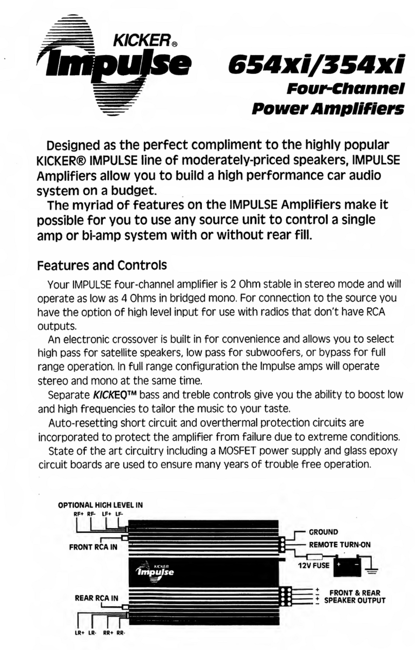
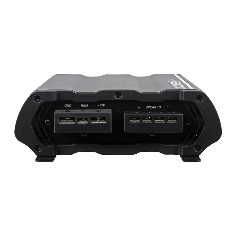
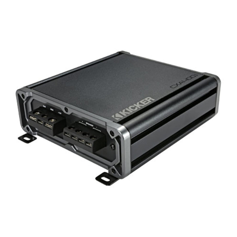
Kicker PXA Mono User manual

PXA Amplifiers
Owner’s Manual
Manual del Propietario
Manuel d’utilisatio
Benutzerhandbuch
select language
seleccione
el idioma
choisir la
langue
sprache
auswählen

2English
Contents
Overview..................................... 3
Specifications................................................ 4
Warranty ................................... 40
Garantía | Garantie..................... 42
PXA Mono
Installation ................................... 5
Mounting....................................................... 5
Wiring ........................................................... 6
Operation.................................... 9
Features........................................................ 9
Troubleshooting......................... 14
PXA 4-CH
Installation ................................. 15
Mounting..................................................... 15
Power Wiring............................................... 16
Speaker Wiring............................................ 19
Operation.................................. 21
Features...................................................... 21
Troubleshooting......................... 26
PXA 5-CH
Installation ................................. 27
Mounting..................................................... 27
Power Wiring............................................... 28
Speaker Wiring............................................ 31
Operation.................................. 33
Features...................................................... 33
Troubleshooting......................... 39
46pxa-d-220124

3English
Overview
IMPORTANT SAFETY WARNING
PROLONGED CONTINUOUS OPERATION OF AN AMPLIFIER, SPEAKER, OR
SUBWOOFER IN A DISTORTED, CLIPPED OR OVER-POWERED MANNER
CAN CAUSE YOUR AUDIO SYSTEM TO OVERHEAT, POSSIBLY CATCHING
FIRE AND RESULTING IN SERIOUS DAMAGE TO YOUR COMPONENTS
AND/OR VEHICLE. AMPLIFIERS REQUIRE UP TO 4 INCHES (10CM) OPEN
VENTILATION. SUBWOOFERS SHOULD BE MOUNTED WITH AT LEAST 1
INCH (2.5CM) CLEARANCE BETWEEN THE FRONT OF THE SPEAKER AND
ANY SURFACE. KICKER PRODUCTS ARE CAPABLE OF PRODUCING SOUND
LEVELS THAT CAN PERMANENTLY DAMAGE YOUR HEARING! TURNING UP A
SYSTEM TO A LEVEL THAT HAS AUDIBLE DISTORTION IS MORE DAMAGING
TO YOUR EARS THAN LISTENING TO AN UNDISTORTED SYSTEM AT THE
SAME VOLUME LEVEL. THE THRESHOLD OF PAIN IS ALWAYS AN INDICATOR
THAT THE SOUND LEVEL IS TOO LOUD AND MAY PERMANENTLY DAMAGE
YOUR HEARING. PLEASE USE COMMON SENSE WHEN CONTROLLING
VOLUME.
The PXA-series have been engineered
to handle the extreme conditions
of powersports and outdoor audio
applications, provide massive amounts of
power, and continue to be cutting-edge
efficient, making them perfect for less
robust charging systems. Use with any
combination of KICKER products, whether
powersports speakers, full-range speakers,
or KICKER’s classic aftermarket speakers.
And don’t let the small, weatherproof
footprint fool you; this amp came to play.

4English
Specifications
Note: All specifications and performance
figures are subject to change. Please visit
www.kicker.com for the most current
information. To get the best performance
from your new KICKER speakers, we
recommend using genuine KICKER
accessories and wiring. Please allow two
weeks of break-in time for the speakers to
reach optimum performance.
Pro Tip: You’re a KICKER amplifier and a
few cables away from a full system upgrade
that will dominate any factory system!
KICKER line of amplifiers make it easy to
upgrade to solid bass with your existing
or stock source unit. Also, ask your dealer
about KICKER Speaker upgrades.
Model: PXA300.1 PXA600.1 PXA400.4 PXA1000.5
Dynamic Power 500W 850W 800W 1400W
RMS Power Output
@ 14.4V, 4Ω stereo, ≤ 1% THD+N
@ 14.4V, 2Ω stereo, ≤ 1% THD+N
@ 14.4V, 4Ω mono, ≤ 1% THD+N
@ 14.4V, 2Ω mono, ≤ 1% THD+N
@ 14.4V, 1Ω mono, ≤ 1% THD+N
150W x 1
250W x 1
300W x 1
300W x 1
500W x 1
600W x 1
100W x 4
100W x 4
200W x 2
100W x 4
100W x 4
200W x 2 (Amp 1 and 2) 300W X 1 (Sub)
500W X 1 (Sub)
600W X 1 (Sub)
Frequency Response [Hz] 25Hz – 200Hz 25Hz – 200Hz 10Hz – 20KHz Full Range 10Hz - 20KHz,
Sub 25Hz - 200Hz
Selectable Electronic Crossover 12dB/Octave
Lo-Pass
60/80/100/120 Hz
12dB/Octave
Lo-Pass
60/80/100/120 Hz
24dB/Octave
Hi-Pass 80/120 Hz,
Lo-Pass (80 Hz only)
24dB/Octave
Hi-Pass 80/120 Hz (Amp1 and Amp2),
Lo-Pass 60/80/100/120 Hz (Sub only)
KickEQ™ Bass Boost Selectable 0/+6db
Bass Boost @ 40 Hz
Selectable 0/+6db
Bass Boost @ 40 Hz
N/A (Sub Only)
Selectable 0/+6db Bass Boost @ 40 Hz
Fader On/Off Switch N/A N/A Yes (2) One for Amp 2, One for Sub Input
Length [in, cm] 9-3/4, 24.8 9-3/4, 24.8 9-3/4, 24.8 12-7/8, 32.8
Height [in, cm] 1-7/8, 4.7 1-7/8, 4.7 1-3/4, 4.5 1-15/16, 5
Width [in, cm] 4-1/2, 11.5
Signal-to-Noise Ratio [dB]
>95dB, a-weighted, re: rated power
>75dB (ref: 1W output)
Input Sensitivity Low Level: 125mV–5V
High Level: 1V–40V

5English
Choose a structurally sound location
to mount your KICKER amplifier. Make
sure there are no items behind the area
where the screws will be driven. Choose
a location that allows at least 4” (10cm) of
open ventilation for the amplifier. Drill four
holes using a 7/64” (3mm) bit and use the
supplied #8 screws to mount the amplifier.
Installation
PXA300.1 | PXA600.1
Mounting

6English
Wiring
Disconnect the vehicle’s battery to avoid an
electrical short. A good ground connection
is important. If the PXA is mounted in the
front fairing of a motorcycle, it will be best
to extend the ground wire all the way to
the battery. Make the ground wire short,
24” (60cm) or less and, if not conneted
to the battery, connect it to a paint-and-
corrosion-free, solid metal area of the
vehicle’s chassis. Adding an additional
ground wire of this same gauge (or larger)
between the battery’s negative post and
the vehicle chassis is recommended. Keep
the audio signal cable away from factory
wiring harnesses and other power wiring. If
you need to cross this wiring, cross it at a
90 degree angle. Install a fuse at the blue
+12V constant wire. Fuse installation should
be as close as possible to the battery, and
no further than 18” (45cm) of the battery,
and in-line with the harness’ power cable,
which is connected to your PXA Amplifier.
Make sure the power wire is routed so that
it will not be damaged, crimped, or shorted.
Model External Fuse (sold separately) Power/Ground Wire KICKER Wiring Kit
PXA300.1 1 x 40 Ampere 8 Gauge KMPK8, PK8, CK8
PXA600.1 1 x 80 Ampere 4 Gauge KMPK4, PK4, CK4
Click Here for Amplifier Install Kits

7English
12V
external fuse
remote turn-on
power
wire
adapters
(if necessary)
ground wire +12V constant wire
remote bass
sub input
≤18”
(45cm)
≤24”
(60cm)
If you ever need to remove the amplifier
from the vehicle after it has been installed,
the ground wire should be the last wire
disconnected from the amplifier; just the
opposite as when you installed it.

8English
For multiple amplifier installations where
distribution blocks are used, each amplifier
should have its proper-rated fuse, or
breaker, installed between the amplifier and
the distribution block within eighteen inches
of the block, or on the distribution block if it
provides for fusing. The primary power wire
should also be fused between the battery
and distribution block, within eighteen
inches of the battery’s positive terminal, with
a fuse or breaker rated at least to the sum
of the individual amplifier’s fuse values, but
doesn’t exceed the capacity of your wiring.
12V
external fuse
to amplifiers
≤18”
(45cm)
external fuse
≤18”
(45cm)
external fuse
power distribution block
battery
≤18”
(45cm)

9English
Operation
Features
Automatic Turn-On: The PXA-series
offers two different automatic turn-on
modes; +12V and DC Offset.
• Remote Turn-On: Run 18 gauge wire from the Remote
Turn-On Lead on your source unit to the blue REM wire
on the PXA amplifier’s wiring harness.
• DC Offset Turn-On: The DC Offset mode detects a
>2.5V DC offset from the HI-Level speaker outputs when
the source unit has been turned on.
To access the operational features of the
PXA amplifier, remove the six Phillips-head
screws from the bottom of the amp which
are covering the operation panel.

10English
Input Level: The RCA inputs on
KICKER PXA amplifiers are capable
of receiving either Hi or Low-level
signals from your source unit. When
using a Hi-Level signal, simply
set the Input Level switch on the
amplifier to HI.
Input Gain Control: The input
gain control is not a volume
control. It matches the output of
the source unit to the input level
of the amplifier. Maximum power
out of the amplifier is possible with
the gain in the lowest position.
Incorrectly setting the gain can result
in distorted output or damage to, and
1
1
2
2
3
3
Input Level Input Gain Control
Crossover & Bass Boost Switches

11English
premature failure of, your speakers. For
a quick setup, turn the source unit up to
about 3/4 volume (if the source unit goes to
30, turn it to 25). Slowly turn up (clockwise)
the gain on the amplifier until you can hear
audible distortion, then turn it down a little.
To use the preferred method of setting the
input gain using a voltmeter or oscilloscope,
begin by turning off the amplifier and
disconnecting all speakers from it. Turn the
gain knob completely off (counterclockwise)
and all crossovers off, or to their least
effective setting. Turn off bass boost. If a
remote bass accessory is connected to the
amplifier, turn it completely on (clockwise).
Ensure all EQ and DSP settings on the
source unit such as bass, treble, fader,
seating position etc are set to linear, flat,
center, or off. Turn on the amplifier. Play a
0dB sine wave through your source unit
and increase the volume to about 3/4
of maximum. Sine wave tracks can be
downloaded for free from KICKER.com
under the “Support” tab. Use the 50Hz sine
wave to set the gain for a subwoofer and
the 1kHz sine wave for full-range speakers.

12English
Set your voltmeter or oscilloscope to
measure AC voltage. Place the voltmeter’s
probes on the amplifier’s speaker output
terminals. With the sine wave playing, slowly
turn the gain knob clockwise and watch the
AC voltage on the voltmeter increase. When
the desired voltage is shown (reference
power chart insert), or you start to see
the waveform square off stop increasing
the gain, turn the amplifier off, reconnect
all speakers and set the crossovers to
your desired setting. Your gain is now set
for maximum unclipped power from the
amplifier. If you increase amplitude using
settings on the source unit or the bass
boost on the amplifier it will introduce
distortion and you will need to redo these
steps.

13English
KICK EQ Bass Boost: The bass boost
is designed to give you increased output,
+6dB, at 40Hz. If you turn it on, you must
readjust the input gain control to avoid
clipping the amplifier.
LO-PASS: Use the LO-PASS switches
to set the internal crossover. Choose a
cutoff of 60Hz, 80Hz, 100Hz, or 120Hz,
depending on the configuration of switches.
Never change the switches with the audio
system on!

14English
Troubleshooting
If your amplifier does not appear to be working, check the obvious things first such as blown
fuses, poor or incorrect wiring connections, incorrect setting of crossover switch and gain
controls, etc. There is a Power Protection LED on the side power panel of your Kicker PXA
series amplifier. Depending on the state of the amplifier and the vehicle’s charging system, the
LED will glow either Red or Blue. When the blue LED is lit this indicates the amplifier is turned
on and no trouble exists.
Blue LED off, no output? With a Volt Ohm Meter (VOM) check the following: +12 volt
power terminal (should read +12V to +16V) Remote turn-on terminal (should read +12V to
+16V) Check for reversed power and ground connections Ground terminal, for proper
conductivity. For Hi-Level input, check input wires for +6V.
Blue LED on, no output? Check the following: RCA connections Test speaker
outputs with a “known” good speaker. Substitute source unit with a “known” good source
unit. Check for a signal in the RCA cable feeding the amplifier with the VOM meter set to
measure “AC” voltage.
Protection LED flashing with loud music? The red LED indicates low battery voltage.
Check all the connections in your vehicle’s charging system. It may be necessary to replace
or charge your vehicle’s battery or replace your vehicle’s alternator.
Protection LED on, no output? Amplifier is very hot = thermal protection is engaged.
Test for proper impedance at the speaker terminals with a VOM meter (see the diagrams in
this manual for minimum recommended impedance and multiple speaker wiring suggestions).
Also check for adequate airflow around the amplifier. Amplifier shuts down only while
vehicle is running = voltage protection circuitry is engaged. Voltage to the amplifier is not
within the 10–16 volt operating range. Have the vehicle’s charging and electrical system
inspected. Amplifier will only play at low volume levels = short circuit protection is
engaged. Check for speaker wires shorted to each other or to the vehicle chassis. Check for
damaged speakers or speaker(s) operating below the minimum recommended impedance.
No or low output? Check the balance control on source unit Check the RCA (or
speaker input) and speaker output connections.
Alternator noise-whining sound with engine’s RPM? Check for damaged RCA
(or speaker input) cable Check the routing of RCA (or speaker input) cable Check the
source unit for proper grounding Check the gain settings and turn them down if they are
set too high.
Reduced bass response? Reverse a speaker connection from positive to negative on the
stereo/subwoofer channel(s); if the bass improves, the speaker was out of phase.
Ground Noise? KICKER amplifiers are engineered to be fully compatible with all
manufacturers’ head units. Some head units may require additional grounding to prevent
noise from entering the audio signal. If you are experiencing this problem with your head unit,
in most cases running a ground wire from the RCA outputs on the head unit to the chassis
will remedy this issue.
CAUTION: When jump starting the vehicle, be sure that connections made with jumper
cables are correct. Improper connections can result in blown amplifier fuses as well as the
failure of other critical systems in the vehicle.
If you have more questions about the installation or operation of your new KICKER product,
see the Authorized KICKER Dealer where you made your purchase. For more advice on
installation, click on the SUPPORT tab on the KICKER homepage, www.kicker.com.
Choose the TECHNICAL SUPPORT tab, choose the subject you are interested in, and then
download or view the corresponding information. Please E-mail support@kicker.com or call
Technical Services (405) 624-8583 for unanswered or specific questions.

15English
Choose a structurally sound location
to mount your KICKER amplifier. Make
sure there are no items behind the area
where the screws will be driven. Choose
a location that allows at least 4” (10cm) of
open ventilation for the amplifier. Drill four
holes using a 7/64” (3mm) bit and use the
supplied #8 screws to mount the amplifier.
Installation
PXA400.4
Mounting

16English
Power Wiring
Disconnect the vehicle’s battery to avoid an
electrical short. A good ground connection
is important. If the PXA is mounted in the
front fairing of a motorcycle, it will be best
to extend the ground wire all the way to
the battery. Make the ground wire short,
24” (60cm) or less and, if not conneted
to the battery, connect it to a paint-and-
corrosion-free, solid metal area of the
vehicle’s chassis. Adding an additional
ground wire of this same gauge (or larger)
between the battery’s negative post and
the vehicle chassis is recommended. Keep
the audio signal cable away from factory
wiring harnesses and other power wiring. If
you need to cross this wiring, cross it at a
90 degree angle. Install a fuse at the blue
+12V constant wire. Fuse installation should
be as close as possible to the battery, and
no further than 18” (45cm) of the battery,
and in-line with the harness’ power cable,
which is connected to your PXA Amplifier.
Make sure the power wire is routed so that
it will not be damaged, crimped, or shorted.
Model External Fuse (sold separately) Power/Ground Wire KICKER Wiring Kit
PXA400.4 1 x 60 Ampere 8 Gauge KMPK8, PK8, CK8
Click Here for Amplifier Install Kits

17English
12V
external fuse
remote turn-on
ground wire +12V constant wire
remote bass
amp1 & amp2
inputs
≤18”
(45cm)
≤24”
(60cm)
If you ever need to remove the amplifier
from the vehicle after it has been installed,
the ground wire should be the last wire
disconnected from the amplifier; just the
opposite as when you installed it.
power
wire
adapters
(if necessary)

18English
For multiple amplifier installations where
distribution blocks are used, each amplifier
should have its proper-rated fuse, or
breaker, installed between the amplifier and
the distribution block within eighteen inches
of the block, or on the distribution block if it
provides for fusing. The primary power wire
should also be fused between the battery
and distribution block, within eighteen
inches of the battery’s positive terminal, with
a fuse or breaker rated at least to the sum
of the individual amplifier’s fuse values, but
doesn’t exceed the capacity of your wiring.
12V
external fuse
to amplifiers
≤18”
(45cm)
external fuse
≤18”
(45cm)
external fuse
power distribution block
battery
≤18”
(45cm)

19English
Speaker Wiring
(4-Channel Operation)
AMP2 right (purple)
AMP2 left (green)
AMP1 left (white)
AMP1 right (grey)

20English
(Bridged Operation)
AMP1 left (white) positive
AMP1 right (grey) negative
AMP2 left (green) positive
AMP2 right (purple negative
You may use a combination of stereo and
bridged operation (eg AMP1 Left & Right,
and AMP 2 Bridged subwoofer)
This manual suits for next models
6
Table of contents
Other Kicker Amplifier manuals

Kicker
Kicker KX400.1 User manual

Kicker
Kicker BX360.4 User manual

Kicker
Kicker IX500.2 User manual

Kicker
Kicker IX254 User manual

Kicker
Kicker KXM800.5 User manual

Kicker
Kicker ZX400.1 User manual

Kicker
Kicker KX800.5 User manual

Kicker
Kicker ZX1000.1 User manual

Kicker
Kicker CX300.4 User manual

Kicker
Kicker KXM400.4 User manual

Kicker
Kicker KEY180.4 User manual

Kicker
Kicker ZX700.5 User manual

Kicker
Kicker KXMA800.5 User manual

Kicker
Kicker CXA600.5 User manual

Kicker
Kicker ZX350.4 User manual

Kicker
Kicker KX100.2 User manual

Kicker
Kicker ZX550.3 User manual

Kicker
Kicker Warhorse WX 10000-1 User manual

Kicker
Kicker BX350.1 User manual

Kicker
Kicker ZX1000.1 User manual