Kieback&Peter TPC70 User manual

Kieback&Peter GmbH & Co. KG
Tempelhofer Weg 50, 12347 Berlin/Germany
Telefon: +49 30 60095-0, Telefax: +49 30 60095-164
www.kieback-peter.de, [email protected]
Datasheet 2.60-10.070-01-EN
TPC70
Issue 2017-09-13
A
Änderungen vorbehalten - Contents subject to change - Sous réserve de modifications - Reservado el derecho a modificación - Wijzigingen
voorbehouden - Con riserva di modifiche - Innehåll som skall ändras - Zmeny vyhradené - Změny vyhrazeny - Zmiany zastrzeżone - Возможны
изменения - A változtatások jogát fenntartjuk - ؍⮉ᵚ㓿䙊⸕㘼᭩ࣘⲴᵳ࣋
Product Description
TPC70Display and Operator Panel
Application
The TPC70 is a remote display and operator panel. It has a
color TFT touchscreen with a screen size of 7″ / 17,8 cm.
The TPC70 can operate a DDC4020e or DDC4040e
automation station.
The TPC70 is equipped with an integrated Ethernet interface
for communication.
The TPC70 is suitable for installation in the front panel.
Configuration is available in two languages (German,
English).
User guide is available in 16 languages (Bulgarian, Czech,
Dutch, English, French, German, Hungarian, Italian, Lithu-
anian, Latvian, Polish, Romanian, Russian, Spanish,
Swedish and Chinese).
Content Page
Important Information Regarding Product Safety ..................................................................................................2
Item........................................................................................................................................................................3
Technical Data.....................................................................................................................................................3
Accessories (included in delivery) .......................................................................................................................3
Accessories (not included in delivery) .................................................................................................................3
Compatibility ........................................................................................................................................................3
Dimensions..........................................................................................................................................................4
Front Panel Cutout...............................................................................................................................................4
Connection...........................................................................................................................................................4
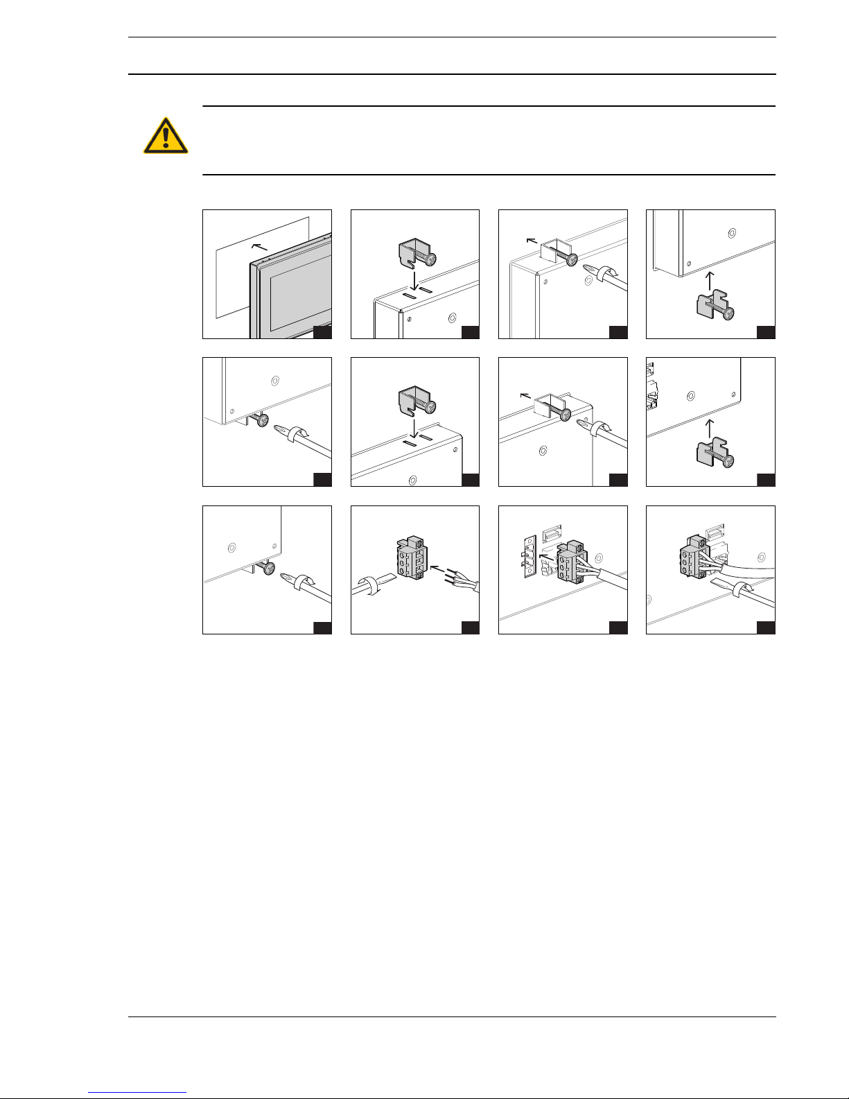
Mounting ................................................................................................................................................................5
Installation..............................................................................................................................................................6
Updating the Software and Calibrating the Touch Panel.......................................................................................8

APage 2 / 8
Product DescriptionTPC70
Datasheet 2.60-10.070-01-EN Issue 2017-09-13
Important Information Regarding Product Safety
Safety Instructions
This data sheet contains information on installing and commissioning the product "TPC70". Each
person who carries out work on this product must have read and understood this data sheet. If you
have any questions that are not resolved by this data sheet, you can obtain further information from
the supplier or manufacturer.
If the product is not used in accordance with this data sheet, the protection provided will be impaired.
Applicable regulations must be observed when installing and using the device. Within the EU, these
include regulations regarding occupational safety and accident prevention as well as those from the
VDE (Association for Electrical, Electronic & Information Technologies). If the device is used in other
countries, it is the responsibility of the system installer or operator to comply with local regulations.
Mounting, installation and commissioning work on the devices may only be carried out by qualified
technicians. Qualified technicians are persons who are familiar with the described product and who
can assess given tasks and recognize possible dangers due to technical training, knowledge and
experience as well as knowledge of the appropriate regulations.
Legend
WARNING
Indicates a hazard of medium risk which can result in death or severe bodily injury if it is not avoided.
CAUTION
Indicates a hazard of low risk which can result in minor or medium bodily injury if it is not avoided.
!CAUTION
Indicates a hazard of medium risk which can result in material damage or malfunctions if it is not
avoided.
NOTE
Indicates additional information that can simplify the work with the product for you.
Notes on Disposal
For disposal, the product is considered waste from electrical and electronic equipment (electronic
waste) and must not be disposed of as household waste. Special treatment for specific components
may be legally binding or ecologically sensible. The local and currently applicable legislation must be
observed.

A
Page 3 / 8
Datasheet 2.60-10.070-01-EN
TPC70Product Description
Issue 2017-09-13
Item
Technical Data
Accessories (included in delivery)
Installation kit for control panel installation (4 clamps)
Power supply mating plug
Accessories (not included in delivery)
Compatibility
The following items can be used with the TPC70:
■DDC4020e as of version 1.16
■DDC4040e as of version 1.16
■DDC4200e as of version 1.12
■DDC4400e as of version 1.12
■DDC4002e as of version 1.12
TPC70 Remote display and operator panel for DDC4020e and DDC4040e
Nominal voltage DC 12 .. 24 V; 7 W
Displays and controls Two-color LED for operating display (Power LED, green) and for display of
malfunction messages (red)
Backlit active matrix LCD:
■Screen size: 7″ / 17,8 cm
■Resolution: 800 x 480 pixels, widescreen format 15 : 9
■LED backlighting
Interfaces Ethernet 10/100/1000-Base-T (RJ45)
Type A USB socket, for SW updates/application only
Housing metal; white aluminum
Level of contamination 2
Method of operation Type 1
Protection class III
Degree of protection IP20 housing / IP65 front
Ambient temperature 0..55 °C
Ambient humidity During operation: 20..80 % r.h., non-condensing
Out of operation: 5 %..90 % r.h.; non-condensing
Mounting Front panel
Certifications CE
This device meets the Class A requirements regarding EMC interference
emission in accordance with EN 55032 and may cause radio interference
in some circumstances.
Weight 0.9 kg
Dimensions
(WxHxD in mm)
203 x 149 x 27
HW-103460 DC 24 V, 25 W power adapter
USBSTICK-DDC-MINI USB flash drive for updates

APage 4 / 8
Product DescriptionTPC70
Datasheet 2.60-10.070-01-EN Issue 2017-09-13
NOTE
Only a part of the screen is used for display (black bars right and left) when using devices DDC4200e,
DDC4400e and DDC4002e.
Dimensions
Front Panel Cutout
A recess with the following dimensions is needed in the switch cabinet to take on the TPC70:
Connection
6,0
23,0
190,0
202,0
136,0
149,0
3,5
15,0
14,5
192,0
± 0,2
138,0
± 0,2
0V=
12V=/24V=
GND USB
RJ45

A
Page 5 / 8
Datasheet 2.60-10.070-01-EN
TPC70Product Description
Issue 2017-09-13
Mounting
WARNING
Contact with live parts of electrical domestic installation can cause death due to electric shock.
Mounting/removal may only be carried out when power is switched off.
The TPC70 can be mounted in the switch cabinet with four mounting brackets.
1 2 3 4
56 7 8
910
10 11
11 12
12

APage 6 / 8
Product DescriptionTPC70
Datasheet 2.60-10.070-01-EN Issue 2017-09-13
Installation
NOTE
A DDC4000 with standard settings is pre-configured (APIPA configuration) in the factory settings of
the TPC70. If the standard settings are appropriate, you can connect the TPC70 without configu-
ration.
Default settings:
■TPC70 IP address: 169.254.19.28
■Automation station IP address: 169.254.19.27
■Gateway IP address: not active
Configuration of TPC70
►Connect the device to the network and power supply.
The configuration screen appears 5 seconds after the operating system starts:
►Tap the “Configure” button.
You can change the following properties of the TPC70 in the configuration menu:
■Language of the TPC70 configuration (English or German)
■IP addresses (TPC70, automation station, gateway)
■Network mask
■Password of the TPC70 configuration
■Screensaver
■Screen brightness
■Display resolution
NOTE
You can go back to the TPC70 configuration level anytime by disconnecting from the network (pulling
the network connector).
LED functions
The LED on the front of the TPC70 shows the DDC alarm state as follows:
■No alarm or 'outgoing confirmed error' → Green
■'outgoing unconfirmed error' → Flashing green
■'incoming confirmed error' → Red
■'incoming unconfirmed error' → Flashing red

A
Page 7 / 8
Datasheet 2.60-10.070-01-EN
TPC70Product Description
Issue 2017-09-13
NOTE
A non-existent connection to a DDC4000 is displayed by a red and green flashing LED.
Configuring the display resolution
►Select "Force classic style for dialogs” in the TPC70 configuration.
The following options will become available:
■[ ] request only classic dialogs from BMS (QVGA)
■[ ] request the optimum dialog style from the BMS (WVGA or QVGA)
NOTE
If a graphic is set as the screensaver for the automation station, the TPC70 will use the same graphic
as screensaver.

APage 8 / 8
Product DescriptionTPC70
Datasheet 2.60-10.070-01-EN Issue 2017-09-13
Updating the Software and Calibrating the Touch Panel
!CAUTION
The update will restore theTPC70 to factory settings.
If necessary, make a note of the configuration before proceeding with the update.
The TPC70 firmware is part of the DDC4000e update as of version 1.16. To update the TPC70, use
the files "ST4K" and "UPDATE":
►Decompress the ZIP files to the root of a USB flash drive.
►Switch off the TPC70 by interrupting the power supply.
►Insert the USB flash drive into the USB socket of the TPC70.
►Start the TPC70.
“Update active” will be displayed during the update.
Touch panel calibration begins after about a minute.
►Tap the middle of the displayed crosses.
►Switch off the TPC70 by interrupting the power supply.
►Remove the USB flash drive from the USB socket of the TPC70.
Table of contents
Other Kieback&Peter Control Panel manuals
Popular Control Panel manuals by other brands

Brother
Brother KE-430F Series Input Check

Honeywell
Honeywell Galaxy Flex Installer manual

Resource Data Management
Resource Data Management DMTouch Commissioning & service guide

LG
LG PRCKD20E owner's manual

LEGRAND
LEGRAND Valena 7700 66 installation instructions

Riello
Riello CPD 35 Preliminary Instructions

FAAC
FAAC 455 D installation manual

Siemens
Siemens FIREFINDER-XLS Installation, operation and maintenance manual

RSI VIDEO TECHNOLOGIES
RSI VIDEO TECHNOLOGIES XT610 COMPLETE SETUP AND PROGRAMMING MANUAL

Spectra
Spectra 1759ex Programming guide

Philips
Philips SBCRU1000 Specifications

Beninca
Beninca MATRIX manual