Kikusui PFX2532 User manual

PART NO. Z1-006-162, IB027413
Jul. 2018
PFX2532
Description
Specifications
Connecting and
Configuring Devices
PC Connection and
Hardware Configuration
Panel Operation and
Protection Function
1
2
3
4
Volt/Thermometer Unit
OP02-PFX
8Slot Unit
SL01-PFX
Voltmeter Unit
OP03-PFX
5
App.
6
7
Operation Manual
Charge/Discharge System
Charge/discharge System Controller
PFX2500 Series
Options
Cleaning the Dust Filter
Explanation of Functions
Troubleshooting
Characteristics of Digital
CC/CV Control
Connecting to a Bias
Power Supply

2PFX2532
Thank you for purchasing the PFX2532 Charge/Discharge System
Controller.
Using a dedicated software application on a PC, you can set the
conditions for battery charge/discharge characteristic tests,
execute the tests, and analyze the test results.
The software application that you use to control the PFX2532
Charge/Discharge System Controller is BPChecker3000.
This application is sold separately.
This manual is intended for first-time users of this product. It
provides an overview of the product and notes on usage. It also
explains how to configure the product, operate the product,
perform maintenance on the product, and so on.
To effectively use the product features, read this manual from
beginning to end. If you forget how to use the product or if a
problem occurs, we recommend that you refer to this manual
again.
After reading this guide, keep it in a safe place for quick reference.
If you find any misplaced or missing pages in the manuals, they
will be replaced.
If the manual gets lost or soiled, a new copy can be provided for a
fee. In either case, please contact your Kikusui agent or distributor.
At that time, inform your agent or distributor of the “Part No.”
written on the front cover of this manual.
Every effort has been made to ensure the accuracy of this manual.
However, if you have any questions or find any errors or omissions,
please contact your Kikusui agent or distributor.
Firmware versions that this manual covers
This manual covers firmware versions 2.0X.
When contacting us about the product, please provide us with:
Model (marked in the top section of the front panel)
The firmware version (see 64 page)
The serial number (marked in the top section of the rear panel)
How to read this guide
This manual is designed to be read from beginning to end. We
recommend that you read it thoroughly before using the PFX2532
Charge/Discharge System Controller for the first time.
Related manuals
For details on BPChecker3000, see the operation manual of the
application.
For details on the PWR-01 series, PWR series Regulated DC Power
supplies, PAT-T series Regulated DC Power supplies, and PLZ-5W
series, PLZ-4W series Electronic Loads, and PLZ2405WB,
PLZ2004WB Electronic Load Boosters, see the corresponding
operation manual.
Intended readers of this manual
These manuals are intended for users of the PFX2532 Charge/
Discharge System Controller and their instructors.
This guide assumes that users have knowledge of charge/
discharge testing of power storage devices.
Trademarks
Windows is either a registered trademarks or trademark of
Microsoft Corporation in the United States and/or other countries.
All company names and product names used in this manual are
trademarks or registered trademarks of their respective
companies.
Copyrights
The contents of this manual may not be reproduced, in whole or in
part, without the prior consent of the copyright holder.
The specifications of this product and the contents of this manual
are subject to change without prior notice.
Copyright 2015© Kikusui Electronics Corporation
About This Manual

PFX2532 3
Check that all accessories are included and that the main unit and
accessories have not been damaged during transportation.
If the main unit or any of the accessories are damaged or missing,
contact your Kikusui agent or distributor.
We recommend that you save all packing materials, in case the
PFX2532 needs to be transported at a later date.
To configure a system, the following cables are necessary in
addition to the included cables.
These cables are available as options (sold separately).
• DC power supply connection cable (+•–): 80 mm2
• Electronic load connection cable (+•–): 80 mm2
• Booster connection cable (+•–): 80 mm2
• DUT cable (+•–) (for connecting the DUT): 80 mm2
• Sensing cable (voltage / temperature sensing cable)
• Booster connection flat cable: 20 core
• I/F cable for PWR-01 Regulated DC power supply
• I/F cable for PLZ-5W Electronic load
• Parallel cable for electronic loads
Make the cables as short as possible by considering the loss in the
cables ( p. 20 ) according to your system configuration.
If cables are to be connected in a system configuration shown in
“Connecting the devices” on page 31, you can use the optional
cable set.
Use it as a guide in selecting the cables.
For information about options, contact your Kikusui agent or
distributor.
Cable set ( p. 123 )
•I/F cable for PWR-01 Regulated DC power supply
(p. 125 )
Checking the Package Contents
Power cord (1 pc.) without plug
(not CE compliant) [85-10-0630]
I/O terminal cover set
Terminal covers (3 pcs.)
Cable ties (6 pcs.)
[Q1-500-085] [P4-200-001]
x 3 x 6
x 6
x 4
[Q1-500-096]
[Q1-900-020] [M1-100-012]
[M5-101-007]
[M4-100-007]
Because the power cord
does not comply with CE, it
may not be included
depending on the shipment
destination.
B
ecause t
h
e power cor
d
does not comply with CE, it
ma
y
not be included
dependin
g
on the shipment
des
tin
a
ti
o
n
.
I/O terminal M8 screw set
(6 sets)
Thermistor (1 pc.)
[38-00-0160]
26-core flat cable (1 pc.)
(I/F cable for PWR1600L
Regulated DC power supplies)
[83-22-6050]
20-core flat cable (1 pc.)
(I/F cable for PLZ-4W
electronic loads)
[91-80-6136]
Sensing Connector (1 pc.)
[84-61-7705]
Lock lever (2 pcs.)
[83-06-5060]
Sensing connector
cover set (1 pc.)
[84-61-8505]
I/F cable for PAT-T Regulated
DC Power Supplies (1 pc.)
[91-88-7330]
LAN cable (1 pc.)
Straight type
Ferrite core for
26-core flat cable (1 pc.)
[96-01-0260]
Ferrite core for
20-core flat cable (1 pc.)
[96-01-0250]
Load input terminal cover set
(4 sets)
Covers, auxiliary bands
Operation manual
(English and Japanese,
1 of each)
[91-88-7330]
[96-01-0210]
Model Description Length Quan
tity
TL10-PFX DC power supply connection
cable
[Solderless terminal: M8–M10]
60 cm(+) 1 pc.
60 cm(-) 1 pc.
Electronic load connection
cable
[Solderless terminal: M8–M8]
60 cm(+) 1 pc.
60 cm(-) 1 pc.
DUT cable
(For connecting the DUT)
[Solderless terminal: M8–M10]
3m(+) 1pc.
3m(-) 1pc.
Sensing cable
(Voltage / temperature sensing
cable: already assembled)
3m 1pc.
Model Description Length Quan
tity
SC07-PFX I/F cable
For between a PFX2532 and PWR-01
Approx.
1m
1pc.
Cables required for system configuration
See
See
See

4PFX2532
•I/F cable for PLZ-5W Electronic load (p. 125 )
• Parallel cable for electronic loads ( PLZ-5W, PLZ-4W)
For the safe use and safe maintenance of this product, the
following symbols are used throughout operation manual and
on the product. Note the meaning of each of the symbols to
ensure safe use of the product. (Not all symbols may be used.)
or
Indicates that a high voltage (over 1 000 V) is used here.
Touching the part causes a possibly fatal electric shock. If
physical contact is required by your work, start work only
after you make sure that no voltage is output here.
DANGER
Indicates an imminently hazardous situation which, if
ignored, will result in death or serious injury.
WARNING
Indicates a potentially hazardous situation which, if
ignored, could result in death or serious injury.
CAUTION
Indicates a potentially hazardous situation which, if
ignored, may result in damage to the product and other
property.
Model Description Length Quan
tity
SC05-PFX I/F cable
For between a PFX2532 and PLZ-5W
Approx.
1m
1pc.
M8 screw set 2 sets
Model Description Length Quan
tity
PC01-PLZ-4W 20-core flat cable
For between PLZ-4Ws and
between boosters
Approx.
30 cm
1pc.
PC02-PLZ-4W 20-core flat cable
For between a PLZ-4W and
booster
Approx.
45 cm
1pc.
PC01-PLZ-5W1
1 OnecableisincludedforthePLZ2405WB(booster).
Parallel operation signal cable
kit
For between PLZ-5Ws and
between a PLZ-5W and
booster
Approx.
30 cm
1pc.
See
Ope
Indicates a prohibited act.
Indicates a warning, caution, or danger. When this
symbol is marked on the product, see the relevant
section in this manual.
Protective conductor terminal.
Chassis (frame) terminal.
On (power supply).
Off (power supply).
In position of a bi-stable push control.
Out position of a bi-stable push control.
Indicates that this product conforms to the
requirements of the Waste Electrical and Electronic
Equipment Directive.
In the EU, this product cannot be disposed of as
domestic household waste.
When disposing of this product, follow the Waste
Electrical and Electronic Equipment (WEEE)
Directive.
In areas outside of the EU, dispose of it as per the
instructions of the local authorities.
Safety Symbols

PFX2532 5
The following safety precautions must be observed to avoid
fire hazards, electric shock, accidents, and device failures.
Keep them in mind and make sure to observe them.
Using the product in a manner that is not specified in this
manual may impair the protection functions provided by the
product.
Users
• This product must be used only by qualified personnel who
understand the contents of this operation manual.
• If an unqualified personnel is to use the product, be sure the
product is handled under the supervision of qualified personnel
(those who have electrical knowledge). This is to prevent the
possibility of personal injury.
Purpose of use
• Never use the product for purposes other than the product’s
intended use.
• This product is not designed or manufactured for general home
or consumer use.
Input power supply
• Use the product within the rated input line voltage range.
• For applying power, use the power cord provided. For details,
see the respective page in this manual.
• The product is an equipment of IEC Overvoltage Category II
(energy-consuming equipment supplied from the fixed
installation).
Cover
• Some parts inside the product are hazardous. Do not remove
the external cover.
Grounding
• The product is IEC Safety Class I equipment (equipment with a
protective conductor terminal). To prevent electric shock, be
sure to connect the protective conductor terminal of the
product to electrical ground (safety ground).
Operation
• Before use, visually check for problems in the power cord,
discharge gun, and high-voltage cable. When checking for
these problems, turn off the circuit breaker of distribution.
• If you notice a malfunction or abnormality in the product, stop
using it immediately, and turn off the circuit breaker of
distribution. Make sure the product is not used until it is
completely repaired.
• Do not disassemble or modify the product. If you need to
modify the product, contact your Kikusui distributor or agent.
Maintenance, inspection, and calibration
• To maintain the performance and safety of the product, we
recommend periodic maintenance, inspection, cleaning, and
calibration.
• To prevent electric shock, be sure to unplug the product before
carrying out maintenance or inspection. Do not remove the
external cover.
• Check periodically that there are no tears or breaks in the power
cord.
• If the panel needs cleaning, gently wipe it using a soft cloth
with water-diluted neutral detergent. Do not use volatile
chemicals such as benzene or thinner.
• This product is calibrated before shipment. To maintain the
product’s performance, we recommend periodic calibration. To
have your product calibrated, contact your Kikusui agent/
distributor.
Service
• Kikusui service engineers will perform internal service of the
product. If the product needs adjustment or repairs, contact
your Kikusui distributor or agent.
Note the following points when moving the
product to the installation location or when
transporting the product.
•TurnthePOWERswitchoff.
Moving the product with the POWER switch turned on may
cause electric shock or damage to the product.
• Remove all wiring.
Moving the product with the cables connected may cause wires
to break or injuries due to the product falling over.
• Increase the number of people or take other safety measures
when carrying the product over a slope or across steps.
• When transporting the product, be sure to use the original
packing materials.
Otherwise, damage may result from vibrations or from the
product falling during transportation.
• Be sure to include this manual.
Safety precautions
Operation
Manual
Line
Voltage
GNL
Check?
Precautions When Moving the Product

6PFX2532
Be sure to observe the following precautions
when installing the product.
• Do not use the product in a flammable atmosphere.
To prevent the possibility of explosion or fire, do not use the
product near alcohol, thinner, or other combustible materials,
or in an atmosphere containing such vapors.
• Avoid locations where the product is exposed to high
temperature or direct sunlight.
Do not install the product near a heater or in areas subject to
drastic temperature changes.
Operating temperature range: 0 °C to +40 °C (32 °F to 104 °F)
Storage temperature range: -10 °C to +60 °C (14 °F to 140 °F)
•Avoidhumidenvironments.
Do not install the product in high-humidity locations such as
near a boiler, humidifier, or water supply.
Operating humidity range: 20 %rh to 85 %rh (no condensation)
Storage humidity range : 0 %rh to 90 %rh (no condensation)
Condensation may form even within the operating humidity
range. If this happens, do not use the product until the
condensation dries up completely.
• Be sure to use the product indoors.
This product is designed for safe indoor use.
• Do not install the product in a corrosive atmosphere.
Do not install the product in a corrosive atmosphere or in
environments containing sulfuric acid mist, etc. This may cause
corrosion of various conductors or reduce the quality of the
connector contacts inside the product, and this could lead to
malfunction, failure, and possibly fire.
• Do not install the product in a dusty location.
Dust accumulation can lead to electric shock or fire.
• Do not use the product in a poorly ventilated location.
Provide adequate space around the product for air to circulate
around it.
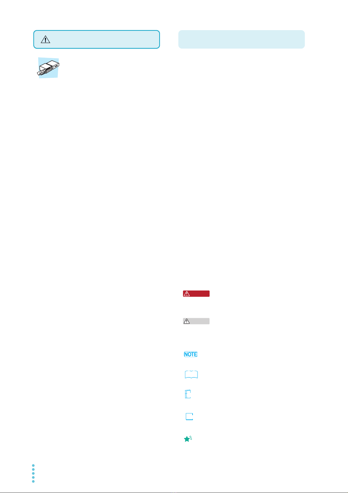
• Do not place objects on top of the product.
Placing heavy objects on top of the product may cause
malfunction.
• Do not install the product on an inclined surface or in a location
subject to vibrations.
The product may fall or tip over and cause damage and injury.
• Do not use the product in a location subject to strong magnetic
or electric fields or in a location where the input power supply
signal contains large amounts of distortion or noise.
Doing so may cause the product to malfunction.
• Use the product in an industrial environment.
This product may cause interference if used in residential areas.
Such use must be avoided unless the user takes special
measures to reduce electromagnetic emissions to prevent
interference to the reception of radio and television broadcasts.
•ForKCmark.
이 기기는 업무용 (A 급 ) 전자파적합기기로서 판매자 또는 사용자는
이 점을 주의하시기 바라며 , 가정외의 지역에서 사용하는 것을 목적
으로 합니다 .
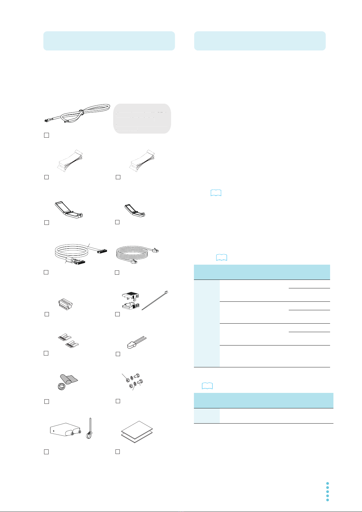
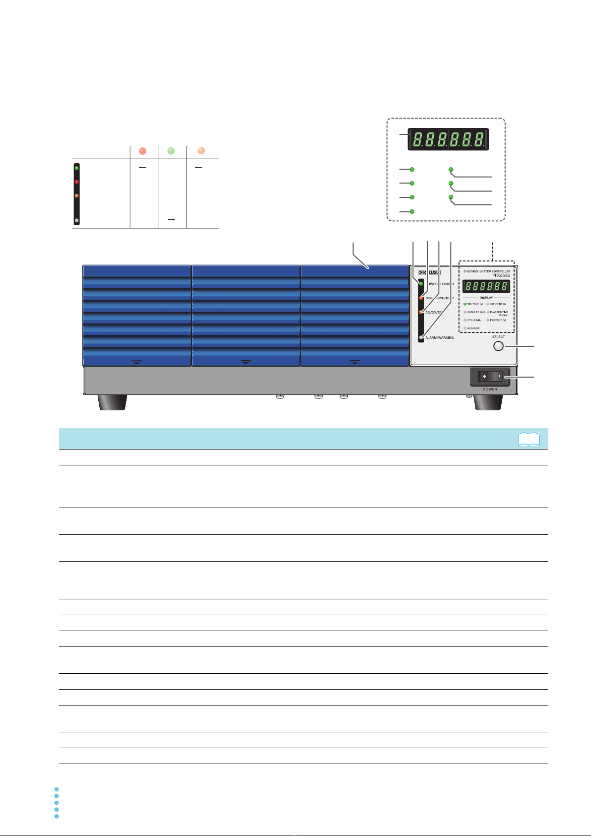
• In this manual, the PFX2532 Charge/Discharge System
Controller is also referred to as the PFX2532 or the PFX2500
series.
• Application software BPChecker3000 is also referred to as
BPChecker3000.
• The PWR-01 Series Regulated DC Power Supply is also referred
to as the PWR-01.
• The PWR Series Regulated DC Power Supply is also referred to as
the PWR.
• The PAT-T Series Regulated DC Power Supply is also referred to
as the PAT-T.
• The PLZ-5W Series Electronic Load is also referred to as the PLZ-
5W.
• The PLZ-4W Series Electronic Load is also referred to as the PLZ-
4W.
• The PLZ2405WB Electronic Load Booster is also referred to as
the PLZ2405WB.
• The PLZ2004WB Electronic Load Booster for the PLZ-4W Series
Electronic Load is also referred to as the PLZ2004WB.
• The OP02-PFX Volt/Thermometer Unit is also referred to as the
OP02-PFX.
• The OP03-PFX Voltmeter Unit is also referred to as the OP03-
PFX.
• The SL01-PFX 8Slot Unit is also referred to as the SL01-PFX.
• The EX01-PFX board for connecting the PFX2532 and the SL01-
PFX is also referred to as the EX01-PFX.
• The term “PC” is used to refer generally to both personal
computers and workstations.
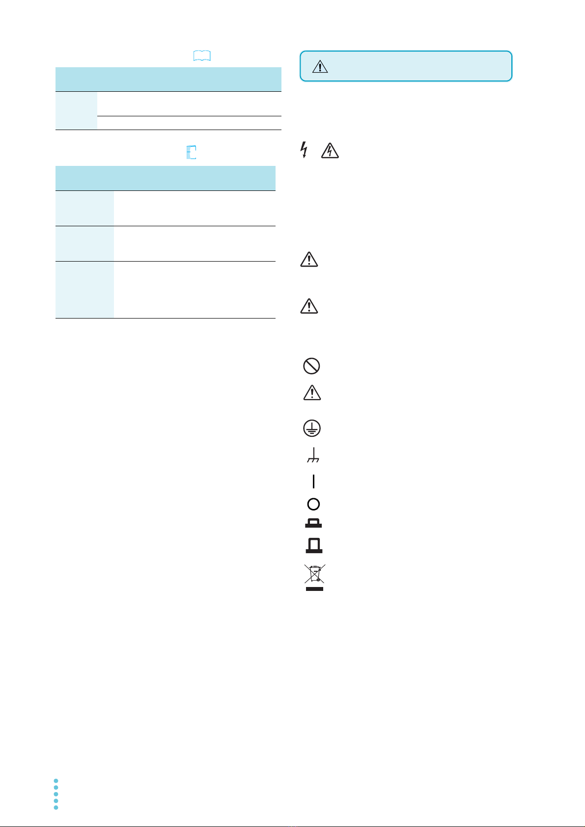
• The following markings are used in the explanations in this
manual.
Indicates a potentially hazardous situation which, if
ignored, could result in death or serious injury.
Indicates a potentially hazardous situation which, if
ignored, may result in damage to the product or other
property.
Indicates information that you should know.
Indicates reference to detailed information.
Indicates reference to detailed information operation manual.
Indicates reference to detailed information help file.
Indicates useful information.
Precautions Concerning Installation
Notations used in this manual
WARNING
CAUTION
See
Ope
?
Help
Memo

PFX2532 7
环境保护使用期限
Environment-friendly Use Period
该标记为适用于在中华人民共和国销售的电子信息产品的环境保
护使用期限。
只要遵守有关该产品的安全及使用注意事项,从制造年月起计算,
在该年度内,就不会对环境污染、人身、财产产生重大的影响。
产品的废弃请遵守有关规定。
产品的制造年月可以在以下网址中确认。
http://www.kikusui.co.jp/pi/
有毒有害物质或元素名称及含有標示
Name of hazardous materials and symbol of element
in the equipment and quantity
本表格依据 SJ/T 11364 的规定编制。
: 该部件所有均质材料的有毒有害物质的含量不超过 GB/T 26572 标准所
规定的极限值要求。
: 该部件至少有一种均质材料的有毒有害物质的含量超过 GB/T 26572 标
准所规定的极限值要求。
10
部件名称
Name of part
有毒有害物质或元素
Hazardous material and symbol of element
铅
Pb
汞
Hg
镉
Cd
六价铬
Cr(VI)
多溴联苯
PBB
多溴二苯醚
PBDE
印刷电路板组装品
内部接线
外壳
底盘组装品
(含变压器)
辅助设备

8PFX2532
Contents
About This Manual 2
Checking the Package Contents 3
Cables required for system configuration 3
Safety Symbols 4
Safety precautions 5
Precautions When Moving the Product 5
Precautions Concerning Installation 6
Notations used in this manual 6
Search by Topic9
Component Names10
1Description
Product Overview 14
System Configuration 16
Performing Stable System Operation 18
Combination for Performing Charge/Discharge
Tests 19
Procedure from System Configuration to Charge/
Discharge Testing 23
2Connecting and
Configuring Devices
Connecting the Power Cord 26
Connecting the Devices 28
Connecting to DC Power Supplies 32
Connecting to the Electronic Load 35
Connecting the Electronic Load and Boosters 39
Preparing to Connect the DUT (Battery) 41
Connecting the DUT (Battery) 43
Configuring the Devices 45
Configuring the PFX2532 45
Configuring the DC Power Supply 47
Configuring the Electronic Load 49
3PC Connection and
Hardware Configuration
Connecting to a PC 54
Assigning IP Addresses 56
Checking the IP address 58
Setting the Model ID 59
Configuring Temperature Chambers 61
4Panel Operation and
Protection Function
Turning the Power On and Off 64
Selecting the Display 66
Overview of External Control 66
Protection Function and Warning Function 68
5Specifications
PFX2532 Functional Specifications 72
PFX2532 Electric Specifications 78
6Volt / Thermometer Unit
OP02-PFX (Option)
Installing the Volt/Thermometer Unit OP02-PFX
86
Preparing to Connect the DUT (Battery) 88
Connecting the DUT (Battery) 91
Volt/Thermometer Unit OP02-PFX Specifications
92
78Slot Unit
SL01-PFX (Option)
Voltmeter Unit
OP03-PFX (Option)
SL01-PFX 8Slot Unit 98
Component Names99
Connecting the Power Cord 101
Connecting to the PFX2532 102
Connecting to a PC 103
Installing the Voltmeter Unit OP03-PFX 106
Preparing to Connect the DUT (Battery) 108
Connecting the DUT (Battery) 111
Turning the SL01-PFX On and Off 112
8Slot Unit SL01-PFX Specifications 114
Voltmeter Unit OP03-PFX Specifications 116
Mounting to the rack 120
Appe
ndix
A Options 122
B Cleaning the Dust Filter 126
C Characteristics of Digital CC/CV
Control127
D Explanation of Functions 129
E Connecting to a Bias power
supply132
F Troubleshooting 134
Index139

PFX2532 9
Search by Topic
Troubleshooting
See “Troubleshooting” on page 134.
• How can I check the accessories? ➔“Checking the Package Contents” p. 3
• What is the best combination to perform
charge/discharge tests?
➔“Combination for Performing Charge/
Discharge Tests” p. 19
• What cables do I need to perform charge/
discharge tests?
➔“Cables required for system
configuration” p. 3
• What cables do I need to prepare to connect
the DUT?
➔“Preparing to Connect the DUT (Battery)” p. 41
• Is there an example showing the connection
of devices for a charge/discharge test
system?
➔“Connecting the Devices”
p. 28
• How do I configure the component devices? ➔“Setting the Model ID” p. 59
• How do I set the protection functions to the
devices?
➔“Protection Function and Warning
Function”
“Configuring the DC Power Supply”
“Configuring the Electronic Load”
p. 68
p. 47
p. 49
• How do I increase the number of
measurement points?
➔“Installing the Volt/Thermometer Unit
OP02-PFX”
“Installing the Voltmeter Unit OP03-PFX”
p. 86
p. 106
• What equipment do I need and how do I
configure them to remotely control the
system from a PC?
➔“Connecting to a PC”
p. 54
• What are the operations that I can perform
from the front panel?
➔“Selecting the Display” p. 66
• How do I check the firmware version? ➔“Turning the POWER switch on” p. 64
• Where can I find the details of the dedicated
application software?
➔BPChecker3000 is sold separately. See
the help file on the BPChecker3000 CD-
ROM.
Io Config, Test Condition Editor,
Test Executive, Graph Viewer
—
• How do I control the connected DC power
supply and electronic load?
➔
PWR-01, PWR, PAT-T, PLZ-5W,
PLZ-4W, PLZ2405WB, PLZ2004WB
—
• How do I perform discharge tests with
voltages that are lower than the minimum
discharge operating voltage?
➔“Connecting to a Bias power supply”
p. 132
• How do I clean the dust filter? ➔“Cleaning the Dust Filter”
p. 126
Preparation
Setup
Operation
?
Help
Ope
Maintenance

10 PFX2532
Component Names
Front panel
ELAPSED TIME
(h
-
min)
DISPLAY
VOLTAGE (V)CURRENT (A)
CAPACITY (Ah)
CYCLE NO. PROTECT (V)
ADDRESS
12345
Status display area
15
Status display area
8
7
6
9
10
11
12
13
14
POWER
/
STANDBY POWER
CHG
/
DISCH
/
REST CHG DISCH REST
CC
/
CV
/
CP CC CV CP
ALARM
/
WARNING ALARM WARNING
Red
Status LED colors and operating status
Green Orange
No. Name Function
1Air inlet (louver) Air inlet for cooling. —
2POWER/STANDBY LED Lights when tests can be executed (POWER: green). —
3CHG/DISCH/REST LED Lights in the charge (CHG: red), discharge (DISCH: green), or rest (REST: orange)
mode. —
4CC/CV/CP LED Lights in the constant current (CC: red), constant voltage (CV: green), or constant
power (CP: orange) mode. —
5ALARM/WARNING LED Lights when an alarm is detected (ALARM: red) or when a protection function
activation warning occurs (WARNING: orange). p. 68
6Display area
Displays the item selected with the SELECT key (voltage, current, capacity,
elapsed time, test cycle, protection function setting, LAN interface information,
alarm information, etc.) and IP address.
p. 56 ,
p. 66 ,
p. 68
7VOLTAGE (V) LED Lights when voltage is displayed (when selected with the SELECT key) p. 66
8CAPACITY (Ah) LED Lights when capacity is displayed (when selected with the SELECT key) p. 66
9CYCLE NO. LED Lights when test cycle is displayed (when selected with the SELECT key) p. 66
10 ADDRESS LED Lights when the connection method, IP address, or channel number is displayed
when the LAN interface is in use (when selected with the SELECT key) p. 56
11 CURRENT (A) LED Lights when current is displayed (when selected with the SELECT key) p. 66
12 ELAPSED TIME (h-min) LED Lights when elapsed time is displayed (when selected with the SELECT key) p. 66
13 PROTECT (V) LED Lights when a protection function setting is displayed (when selected with the
SELECT key) p. 66
14 SELECT key Selects the item to show on the display p. 66
15 POWER switch Turns the power on and off. p. 64
See

PFX2532 11
Rear panel
AC INPUT
100
-
240V
50
/
60Hz
80VA MAX
EXT CONT
S1
SH DET
RESV
8421
NC
TERMN
OFF
1
0
OP02
-
PFX
TERM +
-
+
-
+
-
+
-
1234
THERMO
COUPLE
+
-
+
-
+
-
+
-
1
FG 234
FG
TERM MAX20V
VOLTAGE
SENSING
679
8
10 11 12
1
2
3
4
5
16
15
14
13
Example in which a OP02-PFX Volt/Thermometer Unit is installed in the slot 1
No. Name Function
1EXT CONT terminal block External control terminal p. 66
2LAN port A port for communicating with PC (BPChecker3000) p. 54
3SENSING connector Connector for connecting a sensing cable p. 41 ,
p. 44
4S1 switch Switch for setting the channel number, address, and vibration sensor. p. 45
5 TP-BUS connector1
Connector for maintenance
—
6DC POWER SUPPLY connector Connector for controlling a DC power supply. p. 34
7DC ELECTRONIC LOAD connector Connector for controlling an electronic load p. 38
8Volt/thermometer unit
(OP02-PFX)
An option board for expanding the number of voltage and temperature
measurement points
p. 85 ,
p. 124
9Option slot Slot for installing an optional board.
From the left: slot 1, slot 2, and slot 3
p. 86 ,
p. 124
10 DC ELECTRONICS LOAD
terminal2Input terminal for connecting to an electronic load (DCEL) p. 28 , p. 35
11 DC POWER SUPPLY terminal2Output terminal for connecting to a DC power supply (DCPS) p. 28 , p. 32
12 DUT terminal2Terminal for connecting to the DUT p. 28 , p. 43
13 Air outlet Air outlet for cooling —
14 Serial number — —
15 Chassis terminal A connector for grounding the output. p. 30
16 AC INPUT terminal2AC inlet p. 26
1 A seal is affixed when the product is shipped from the factory.
2 A protection cover is attached when the product is shipped from the factory.
See
Do not remove the seal.
Touching the internal pins can cause electric shock.
WARNING

12 PFX2532
This page is intentionally blank.

Description
This chapter describes the product, the
devices that can be connected to the product,
and the procedure from charge / discharge
test preparation to test execution.

14 PFX2532
Product Overview
The PFX2532 is a dedicated charge / discharge system controller used to measure the charge /
discharge voltage and current of batteries and the like with high accuracy in combination with
Kikusui’s DC power supplies and electronic loads to evaluate the characteristics of DUTs (power
storage devices such as rechargeable batteries). Depending on the DC power supply and electronic
load combination, large capacity, and wide rating range evaluation tests can be performed.
Features
Charge / discharge control system
●Support for large capacity battery modules
Advanced batteries with increasing capacity are supported.
A test system can be set up quickly by combining Kikusui’s DC power supplies PAT-T and
electronic loads PLZ-4W.
●Wide range of ratings
Wide range of ratings can be supported by selecting the appropriate combination of Kikusui’s
DC power supplies and electronic loads. Implementation cost can be suppressed by selecting
the appropriate devices for your charge / discharge test conditions.
●Digital constant current (CC) / constant voltage (CV) control method
The adoption of the digital CC / CV control method minimizes the disparities in the constant
current (CC) / constant voltage (CV) setting accuracy and drift characteristics due to the
differences in the system component devices (DC power supplies and electronic loads). This
ensures highly accurate tests. There is absolutely no need to make adjustments after system
configuration.
●Highly accurate measurement
Highly accurate measurement circuits are built in. Battery voltage and charge / discharge
current are detected with high accuracy. (Voltage measurement: 100 µV resolution, current
measurement: 100 µA resolution, elapsed time measurement: monthly error of 30 s or less (10
ppm or less))
True electric energy and integrated capacity can be measured even for pulse currents that are
difficult to be captured.
●Protection functions
The PFX2532 has a built-in path switch (load switch). The path switch is equipped with a high-
speed shutoff function that quickly detaches DC power supplies and electronic loads when an
error is detected.
It also detects electric potential difference that exceeds specified values in DUT cables and
voltage sensing wires, wiring errors, poor DUT (battery) connection, and so on to prevent
damage to the connected devices and DUTs (batteries).
For the system requirements, see the BPChecker3000 application software’s setup guide.

PFX2532 15
Product Overview
1
Description
●Vibration sensor
In a disaster or the like, the PFX2532 detects large shaking and shock during charge / discharge
test and turns off the output. This prevents damage to the connected devices and DUTs
(batteries).
●10 000-step pattern charge / discharge feature
You can set up to 10 000-step CC or CP (with V or I limits) steps.
High-speed charge / discharge switching control enables you to perform complicated charge /
discharge tests with step times as short as 100 ms. The PFX2532 can be used to create a wide
variety of test and simulation patterns for standard tests.
●High-speed charge / discharge switching
Traditionally, it has taken time to switch between controlling DC power supplies and controlling
electronic loads. This product can be used to control DC power supplies and electronic loads at
the same time, which enables seamless charge / discharge switching.
●High-speed sampling as fast as 1 sample / ms
Voltage and current can be measured at an interval as short as 1 ms with the specified voltage
or current step as the trigger. You can acquire highly accurate voltage waveforms that are
synchronized with the step current. This is an optimal feature for analyzing test impedance and
evaluating service life of DUTs.
●Expandable cell monitor measurement feature
By installing a Volt/Thermometer Unit OP02-PFX (sold separately), you can expand the number
of measurement points by 4 voltage and 4 temperature measurement points. You can expand
the number of measurement points by a maximum of 12 voltage and 12 temperature
measurement points.
If you further need to expand the number of voltage measurement points, you can increase the
number to 72 by installing OP03-PFX Voltmeter Units (sold separately) in a 8 Slot Unit SL01-PFX
and installing a Volt/Thermometer Unit OP02-PFX (sold separately) in the PFX2532 main unit.
●Cell CV function
A cell CV function is available in addition to the cell unbalance detection function. During
charging, the PFX2532 instantly detects the highest cell voltage and controls the charging
operation so that the specified cell CV value is reached. During discharging, the PFX2532 does
the same for the lowest cell voltage.
Safe charge/discharge is possible even on battery modules with unbalanced cells.
●Support for EV standards
The system supports tests for EV-related standards such as the IEC standards. It is easy to use
and works well with Microsoft Office software. It also has features for displaying and exporting
high-speed sample data.

16 PFX2532
System Configuration
The following figure shows a basic configuration example of a charge / discharge system that uses
the PFX2532. The system consists of a PFX2532, Kikusui’s DC power supplies and electronic loads,
and peripheral subsystems.
The PFX2532 functional block is mainly made up of a DUT voltage / current / temperature
measurement section, a digital constant current / constant voltage control section, a power supply
/ electronic load I / F section, a host communication control section, and a load switch.
The PFX2532 has an interface that directly connects to Kikusui’s power supplies and electronic
loads. The system is designed to allow full-scale charge / discharge testing with easy initial
configuration without extra equipment or external circuits.
The connection status of DC power supplies, electronic loads, and DUT (battery) is constantly
monitored. If a problem is detected in any of the devices, the charge / discharge test is safely
aborted.
The PFX2532 is controlled from a PC through the LAN interface.
Application software BPChecker3000 is used to configure and control charge / discharge test
conditions. For details on the application software, see the corresponding help file.
ADC
CC
Protection
control
Communication control
Isolator
Load switch control
Time
base
Digital
CC control
Sequence
control
Digital
CV control
Digital
CP control
Pulse
control
Option communication
SDRAM
Measurement memory
Load switch
Current
measurement
Voltage measurement protection
DUT
Cell compatible
voltage /
temperature
measurement
board (option)
I/F
LAN
CC/CV
.....
+
+
+
+
+ +
+S
-S
DC power supply Electronic load
I/F
BPChecker3000
DAC
DAC
Analog I/F
Indicator
Current detection
Charge/discharge system configuration example
PFX2532
Voltage Sensing
Cell voltage
Cell
temperature
Analog I/F
Voltage
Sensing
BPChecker3000
Hardware configuration Io Config
Test condition creation Test Condition Editor
Test execution Test Executive
Test result analysis Graph Viewer
?
Help

PFX2532 17
System Configuration
1
Description
The above figure shows a system configuration example in which a Charge / Discharge System
Controller PFX2532, Regulated DC Power Supplies PAT40-200T, a Electronic Load PLZ1205W, and a
PLZ2405WB booster 2 units are rack mounted and a PC and a temperature chamber are added.
If you configure a system with the Charge / Discharge System Controller PFX2532, you can connect
charge / discharge units with 72 voltage measurement points and 8 temperature measurement
points or 12 voltage measurement points and 12 temperature measurement points to up to 7
channels (using options1).
Synchronized testing with a temperature chamber is also possible. An ESPEC temperature chamber
is connected to the PC through a dedicated USB-RS485 converter2. To perform a synchronized test
with a temperature chamber, you need a VISA 3library.
USB
RS485
Electronic load
booster
PLZ2405WB
Electronic load
PLZ1205W
Charge /
Discharge System
Controller
PFX2532
Regulated
DC Power Supply
PAT40-200T
EIA rack
Charge / discharge unit, one channel
Application software
BPChecker3000
Configuration example of a 2-channel charge / discharge system
USB-RS485 converter
Temperature chamber
by Espec that can be
controlled through RS485
PC
LAN
cable
To LAN port
Synchronized test
1 The Volt / Thermometer Unit OP02-PFX, which is installed in the PFX2532, and the Voltmeter Unit
OP03-PFX, which is installed in the optional 8Slot Unit are available.
2 Use a converter specified by ESPEC Corporation.
3 VISA (Virtual Instrument Software Architecture) was developed by the VXIplug&play Systems
Alliance. It is the standard specification for measurement instrument connection software. KI-VISA
is a Kikusui-original VISA library that complies with the VXIplug&play VISA specifications. You can
download the latest version of KI-VISA from the Kikusui website (http://www.kikusui.co.jp/en/
download).

18 PFX2532
Performing Stable System Operation
Switching hub
or router
Wi-Fi router
Notebook PC
PC for executing tests (Test Executive) PC for data analysis (Graph Viewer)
Uninterruptible
power supply
DC power supply
PFX2532 Charge/Discharge System
AC power strip for PC and peripherals
(with a grounding terminal)
AC powr cable
Shutdown signal
LAN cable
8Slot Unit
SL01-PFX
Charge/Discharge
System Controller
PFX2532
Electronic load
Electronic load
booster
Electronic load
booster
Using a notebook PC
for executing tests is
advantageous in that
you do not need to
use a UPS.
After configuration is
complete, do not
connect the system to
the Internet or
corporate LAN during
charge/discharge
tests. Avoid using
wireless LAN for
connections.
Install a UPS. Be sure to
connect the shutdown signal.
Connecting the shutdown
signal allows BPChecker3000
to automatically shut down the
charge/discharge system in a
safe and orderly manner even
when a power outage occurs
or when the system suddenly
stops for some other reason.
It is safer to use
separate AC
power supplies for
the PC and the
charge/discharge
system.
If you need to run tests for a long time,
using separate PCs for testing and data
analysis will reduce the load placed on the
PCs and allow the tests to run smoothly.
Ideal system shutdown when a power outage
or sudden interruption occurs (executed
automatically)
The PFX2532 charge/discharge system turns off.
Ļ
The PC remains on using the power from the UPS.
Ļ
BPChecker3000 detects a communication error.
(Io Err)
Ļ
BPChecker3000 process and protects the test file.
Ļ
A few minutes later, the UPS sends the PC a
shutdown signal.
Ļ
The PC powers off.
Suggestions for the PC executing
tests
• Turn off the PC’s sleep mode.
• Set Windows Update to manual mode.
• If possible, do not install virus protection
software.
• Do not run other programs.
• Connect a uninterruptible power supply.
Multicore
processor
8 GB memory
recommended
Replacement
with a
notebook PC
Switchboard or an AC power strip for
charge/discharge devices
(with a grounding terminal)
I MON OUTOUT TRIG
REMOTE
×
×

PFX2532 19
1
Description
Combination for Performing Charge/Discharge Tests
With the PFX2532, the following combination can be used to perform charge / discharge tests.
p. 59 Model IDs are assigned to different combinations of devices used for charge / discharge tests. To
execute a charge / discharge test, you need to set an appropriate model ID according to the
combination of devices to be connected.
The charge / discharge operation range (maximum voltage and maximum current) that can be
used for charge / discharge testing varies depending on the DC power supplies and electronic
loads that are connected to the PFX2532.
■Possible combinations
Combinations whose model IDs have not been determined are planned to be available through
version updates.
For the latest combination information, visit the product information page on our website (http://
www.kikusui.co.jp/en). For details, contact your Kikusui agent or distributor.
See
Model
ID
DC power supply Electronic Load Maximum
charge
power 1
1 It may not be possible to use up to the power specified here due to loss in cables.
Maximum
discharge
power
7301 2
2 Factory default settings
PWR1600L
(two units in parallel) PLZ1004W (H range)+PLZ2004WB 3200 W 3000 W
7302 PAT60-133T PLZ1004W (H range)+PLZ2004WB x2
(2 units in parallel)3
3 Can be replaced with the Kikusui SR Large Capacity Electronic Load Smart Rack System PLZ5004W.
8000 W 5000 W
7303 PAT40-200T PLZ1004W (H range)+PLZ2004WB x2
(2 units in parallel)38000 W 5000 W
7304 PAT40-200T PLZ1004W (H range)+PLZ2004WB 8000 W 3000 W
7305 PWR1600L PLZ1004W (H range) 1600 W 1000 W
7306 PAT40-200T PLZ1004W (H range) 8000 W 1000 W
7307 PWR1600L PLZ1004W (H range)x2 (2 units in parallel) 1600 W 2000 W
7351 PWR1201L PLZ1205W (H range) 1200 W 1200 W
7352 PWR1201L PLZ1205W (H range)x2 (2 units in parallel) 1200 W 2400 W
7353 PAT60-133T PLZ1205W (H range)+PLZ2405WBx2
(2 units in parallel)4
4 Can be replaced with the Kikusui SR Large Capacity Electronic Load Smart Rack System PLZ6005W.
7980 W 6000 W
7354 PAT40-200T PLZ1205W (H range) 8000 W 1200 W
7355 PAT40-200T PLZ1205W (H range)+PLZ2405WB 8000 W 3600 W
7356 PAT40-200T PLZ1205W (H range)+PLZ2405WBx2
(2 units in parallel)48000 W 6000 W
7357 PAT40-200T PLZ1205W (H range)+PLZ2405WBx3
(3 units in parallel) 8000 W 8400 W
7358 PAT40-200T PLZ1205W (M range)+PLZ2405WBx4
(4 units in parallel)5
5 Can be replaced with the Kikusui SR Large Capacity Electronic Load Smart Rack System PLZ10005W.
8000 W 10800 W
7359 PAT80-100T PLZ1205W (M range)+PLZ2405WBx4
(4 units in parallel)56000 W 10800 W

20 PFX2532
Combination for Performing Charge/Discharge Tests
Selecting the appropriate DC power supplies and electronic
loads
The range is different between charging and discharging. Select DC power supplies and electronic
loads that meet each condition.
The graph below shows the range of chargeable voltage and current using the following equation.
Use devices whose voltage (constant voltage, cutoff voltage) and current (constant current) do not
exceed the range.
Maximum charge power = Maximum rated power of DC power supply – Loss in cables1
1 What is loss in cables?
Voltage drops occur as a result of charge currents flowing through DUT cables, connection
cables, PFX2532 current path circuits, and so on. Loss in cables is the power loss during
charging due to this voltage drop. The maximum power that can be used for charging is the
resultant value after subtracting the loss in cables.
If the allowable power of DC power supplies is exceeded during charging, PS / B alarm or the like
occurs, and the test is aborted.
Voltage (V) axis Constant voltage value (CV Voltage) or cutoff voltage value (Cutoff voltage)
Current (A) axis Constant current value (CC Current)
0
10
20
20 40 60 80 100 120 140 160 180 200
30
40
50
60
70
PWR1600Lx2
PAT60-133T
PAT40-200T
PWR1201L
Voltage (V)
Charge operating range of the each DC power supply [PAT-T/ PWR-L/ PWR-01L]
DUT cable: At nominal cross-sectional area 80 mm2 3 m
PFX2532
operating range
Current (A)
Table of contents
Other Kikusui Controllers manuals