21
Package P
Package M x 2
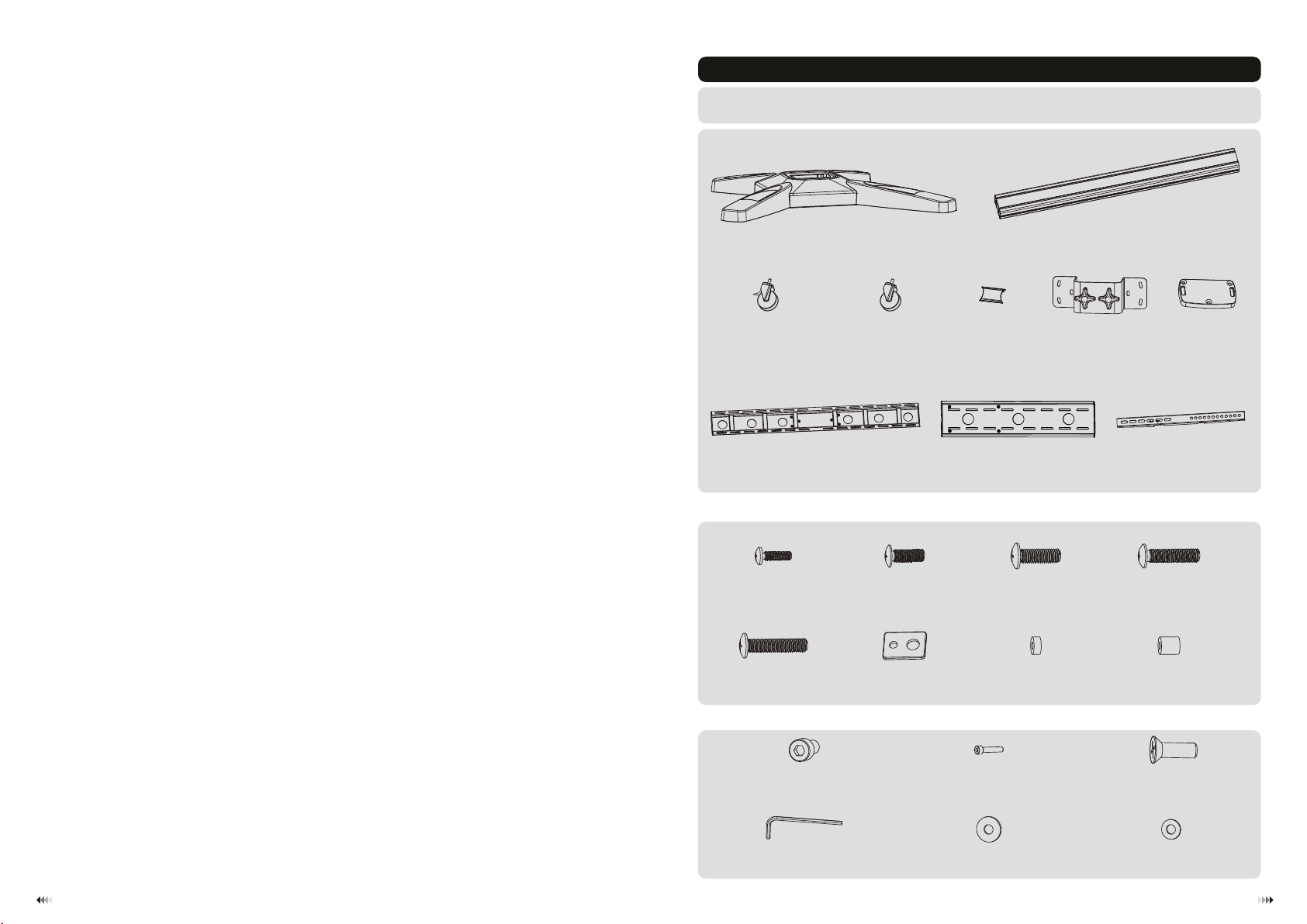
washer
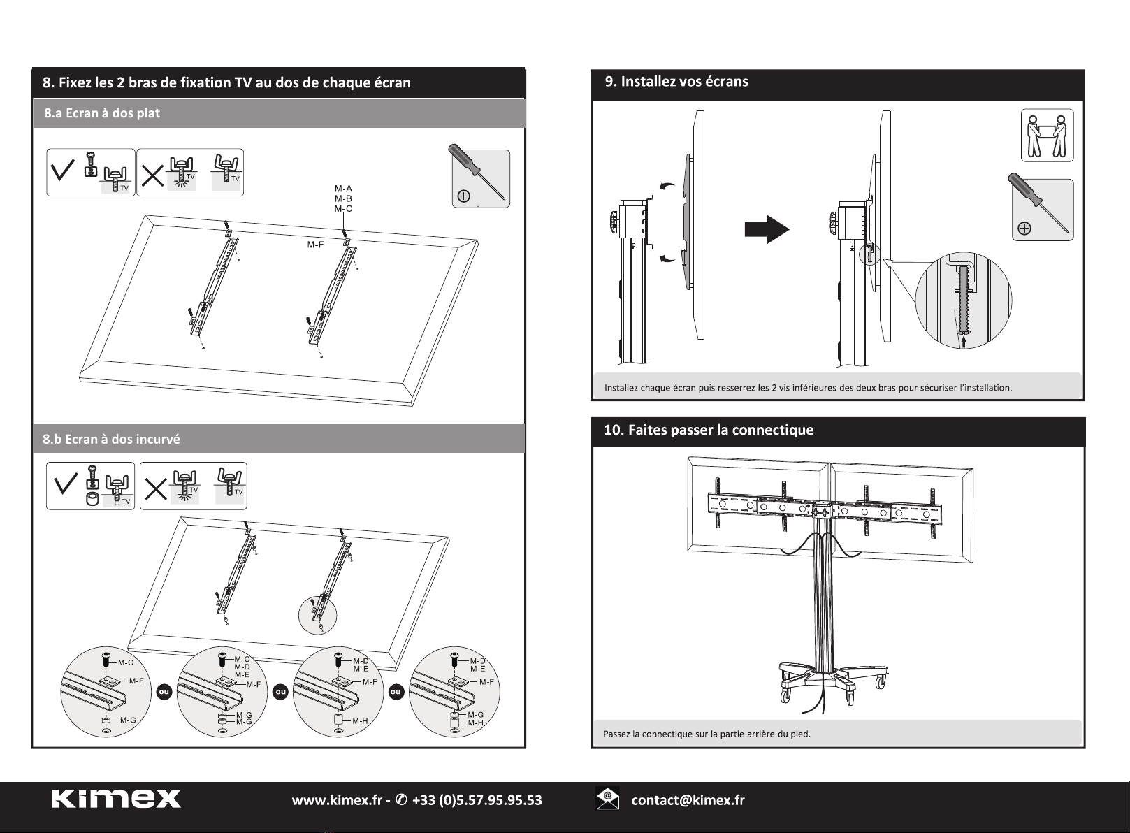
M-F
(x4)
M8x20 (x4)
M-C
M5x14 (x4)
M-A
M6x14 (x4)
M-B
big spacer (x4)
M-H
M6x30 (x4)
M-D
M8x30 (x4)
M-E
small spacer (x8)
M-G
M8x15 (x14)
P-A
M8x40 (x3)
P-B
6mm Allen key (x1)
P-D
D8 washer (x6)
P-E
M8x15 (x3)
P-C
Component Checklist
column (x1)
B
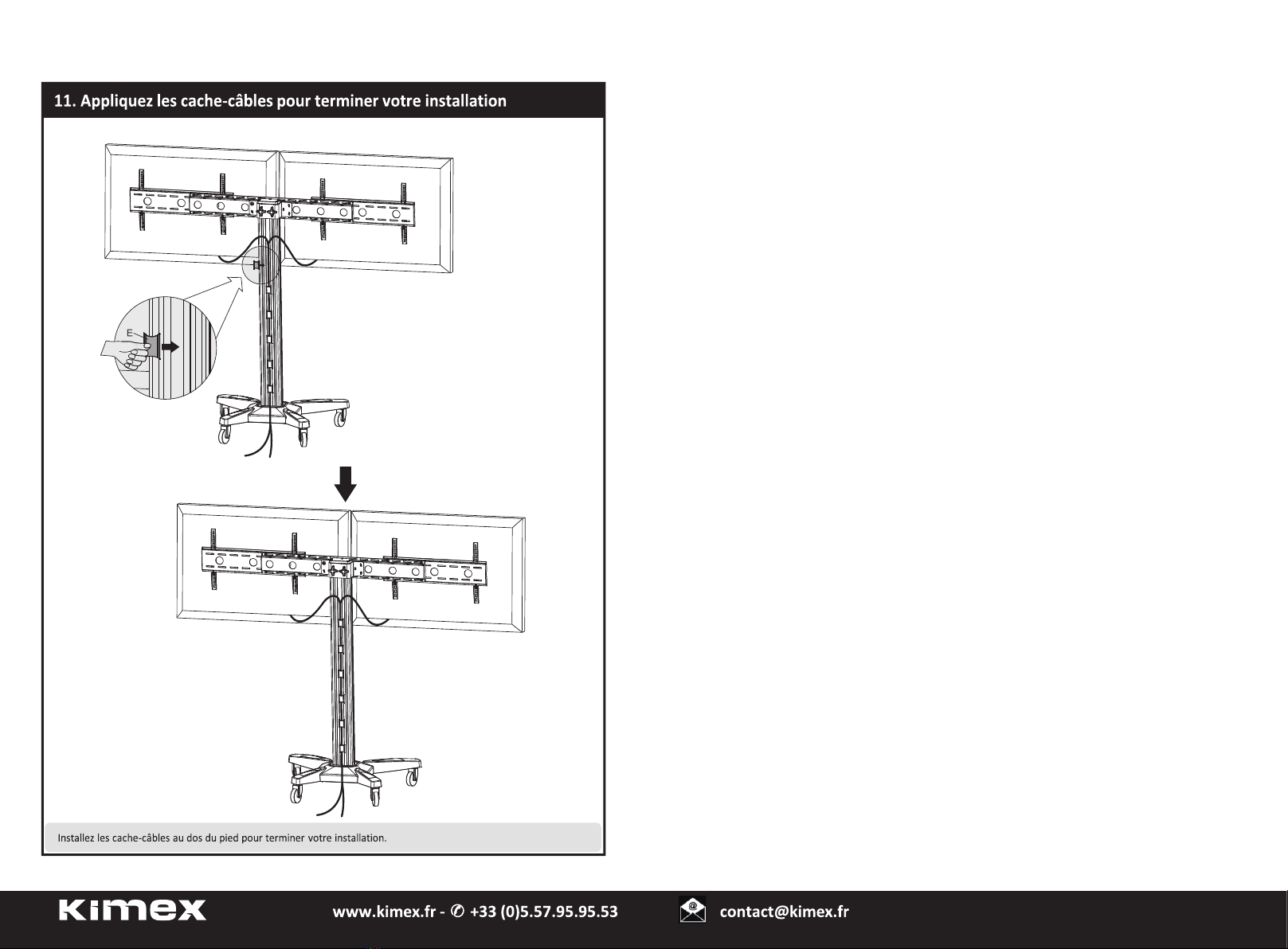
cable clip (x6)
E
IMPORTANT: Ensure that you have received all parts according to the component checklist prior to installation.
If any parts are missing or faulty, telephone your local distributor for a replacement.
wheel caster (x2)
D
wheel caster/brake (x2)
C
fixing piece (x1)
F
top cover (x1)
G
universal plate (x2)
I
adapter bracket (x4)
J
base (x1)
A
big universal plate (x1)
H
D8 washer (x8)
P-F
O
O