Kimray R2L Owner's manual

HIGH PRESSURE CONTROL VALVE
R2L ACTUATOR

HIGH PRESSURE CONTROL VALVEHIGH PRESSURE CONTROL VALVE
Model: R2L ACTUATOR
Installation, Operation & Maintenance Guide
Model: R2L ACTUATOR
Installation, Operation & Maintenance Guide
All Rights Reserved.
All contents of this publication including illustrations are believed to be
reliable. And while efforts have been made to ensure their accuracy, they
are not to be construed as warranties for guarantees, express or implied,
regarding Kimray products or services described herein or their use or
application. All sales are governed by our terms and conditions, which are
available on request.
Kimray reserves the right to modify or improve the designs or specications
of such products at any time without prior notice.
©2015 Kimray Inc.

HIGH PRESSURE CONTROL VALVEHIGH PRESSURE CONTROL VALVE
Model: R2L ACTUATOR
Installation, Operation & Maintenance Guide
Model: R2L ACTUATOR
Installation, Operation & Maintenance Guide
3
www.kimray.com
Contents
A Before you start........................... 4
A1 Scope ................................ 4
A2 Introduction ............................ 4
A3 Description ............................ 4
A4 Maintenance ........................... 4
A5 Changes & Updates ..................... 4
A6 Special Tools & Equipment................ 5
A7 Orientation ............................ 6
1 Installation ............................... 7
2 Start-up & Test............................ 7
DISASSEMBLY
3 Adjustment Screw Assembly................ 8
INSPECTION
4 Inspection & Cleaning...................... 9
ASSEMBLY
5 Mounting Yoke, Adjustment Screw & O-Ring.. 10
6 Spring Disc, Stem, Guide Rods, Stem Carrier . 11
7 Bearing Support ......................... 12
8 Race Bearing, Thrust Bearing, Rotary Shaft,
Cam Followers........................... 13
9 Cover, Flange Adapter, Rod Wiper .......... 14
10 Serial Tag ............................... 14
TESTING
11 Actuator Test ............................ 15

www.kimray.com
HIGH PRESSURE CONTROL VALVEHIGH PRESSURE CONTROL VALVE
Model: R2L ACTUATOR
Installation, Operation & Maintenance Guide
Model: R2L ACTUATOR
Installation, Operation & Maintenance Guide
4
A4 Maintenance
Maintenance should be performed on a regular basis.
Initial intervals of 12 months is recommended. The
maintenance interval may increase or decrease
depending on changing application environments.
WARNING:
DO NOT remove the Actuator from the valve while the
valve is still pressurized.
Always wear protective gloves, clothing, and eyewear
when performing any maintenance operations to avoid
personal injury.
Disconnect any operating lines providing electric power,
or a control signal to the Actuator. Be sure the Actuator
cannot suddenly open or close the valve.
Use bypass valves or completely shut off the process to
isolate the valve from process pressure. Relieve process
pressure on both sides of the valve. Drain the process
media from both sides of the valve.
Use lock-out procedures to be sure that the above
measures stay in effect while you work on the
equipment.
Related Publications
The following publications are applicable for the Actuator.
Number Type Title
See catalog section E1 for product pages.
Abbreviations / Acronyms
The abbreviations that follow are used in this manual.
Term Denition
Commonly Replaced Parts
Occasional Replacement Parts
See repair kit
A5 Changes & Updates
A Before you start
CAUTION:
The instructions provided herein should be completely
reviewed and understood before operating or repairing
this equipment. All CAUTION and WARNING notes
must be strickly observed to prevent personal injury or
equipment damage.
A1 Scope
Do not install, operate, or maintain a R2L adapter
without being fully trained and qualied with the Kimray
installation, operation and maintenance manual.
To avoid personal injury or property damage, it is
important to carefully read, understand, and follow all the
contents of this manual, including all safety cautions and
warnings.
If you have any questions about this manual, contact
your Kimray applications support group before
proceeding.
A2 Introduction
This repair manual contains information for the R2L
adapter.
A3 Description
The R2L adapter is an open Yoke design with standard
Coupling Block and mounting hardware to valve.
The R2L adapter is a weather tight and maintenance free
design.

HIGH PRESSURE CONTROL VALVEHIGH PRESSURE CONTROL VALVE
Model: R2L ACTUATOR
Installation, Operation & Maintenance Guide
Model: R2L ACTUATOR
Installation, Operation & Maintenance Guide
5
www.kimray.com
SPECIAL TOOLS & EQUIPMENT
A6
Kimray reserves the right to modify or improve the special tools & equipment designs or specications at anytime without notice.
NOTICE:
The Kimray R2L Actuator DOES NOT require special
tools for disassembly, inspection and assembly.

www.kimray.com
HIGH PRESSURE CONTROL VALVEHIGH PRESSURE CONTROL VALVE
Model: R2L ACTUATOR
Installation, Operation & Maintenance Guide
Model: R2L ACTUATOR
Installation, Operation & Maintenance Guide
6
Kimray reserves the right to modify or improve the designs or specications of such products at anytime without notice.
Item Description Qty
1 Rod Wiper 1
2 Screws 4
3Flange Adapter 1
4 Lock Nuts 4
5 Dust Cover 1
6 Thrust Bearing Races 4
7 Thust Bearings 2
Item Description Qty
8 Rotary Shaft 1
9 O-Ring 2
10 Bearing Support 1
11 Lock Nut 1
12 Stem Carrier 1
13 Cam Followers 2
14 Guide Rods 4
Item Description Qty
15 Disc Springs 4
16 Stem 1
17 Mounting Yoke 1
18 Adjusting Screw Assembly 1
19 Travel Indicator Assembly 1
20 Screws 4
See catalog section E1 for product size & description.
✴ Recommended spare parts and stocked as repair kits
A7
ORIENTATION
9
7
5
19
18
17
20
16
14
12
10
13
15
7
8
11
6
9
2
6
3
1
4
(See Detail on page 8)
✴
✴
✴
(3 req'd for 1")
✴
✴
✴
✴
NOTE:
Heat may be applied to remove
the old Cam Followers (Item 13)
from the assembly.
✴
✴
✴
✴
✴
✴

HIGH PRESSURE CONTROL VALVEHIGH PRESSURE CONTROL VALVE
Model: R2L ACTUATOR
Installation, Operation & Maintenance Guide
Model: R2L ACTUATOR
Installation, Operation & Maintenance Guide
7
www.kimray.com
1 Installation
If the Actuator has been shipped separately for installation
on a Kimray Valve Body, or if the Actuator was removed
for maintenance, mount the Actuator by following the
instructions presented in this section. Inspect the surface
of the Mounting Yoke and clean the mating valve surface
to remove scale, chips and debris.
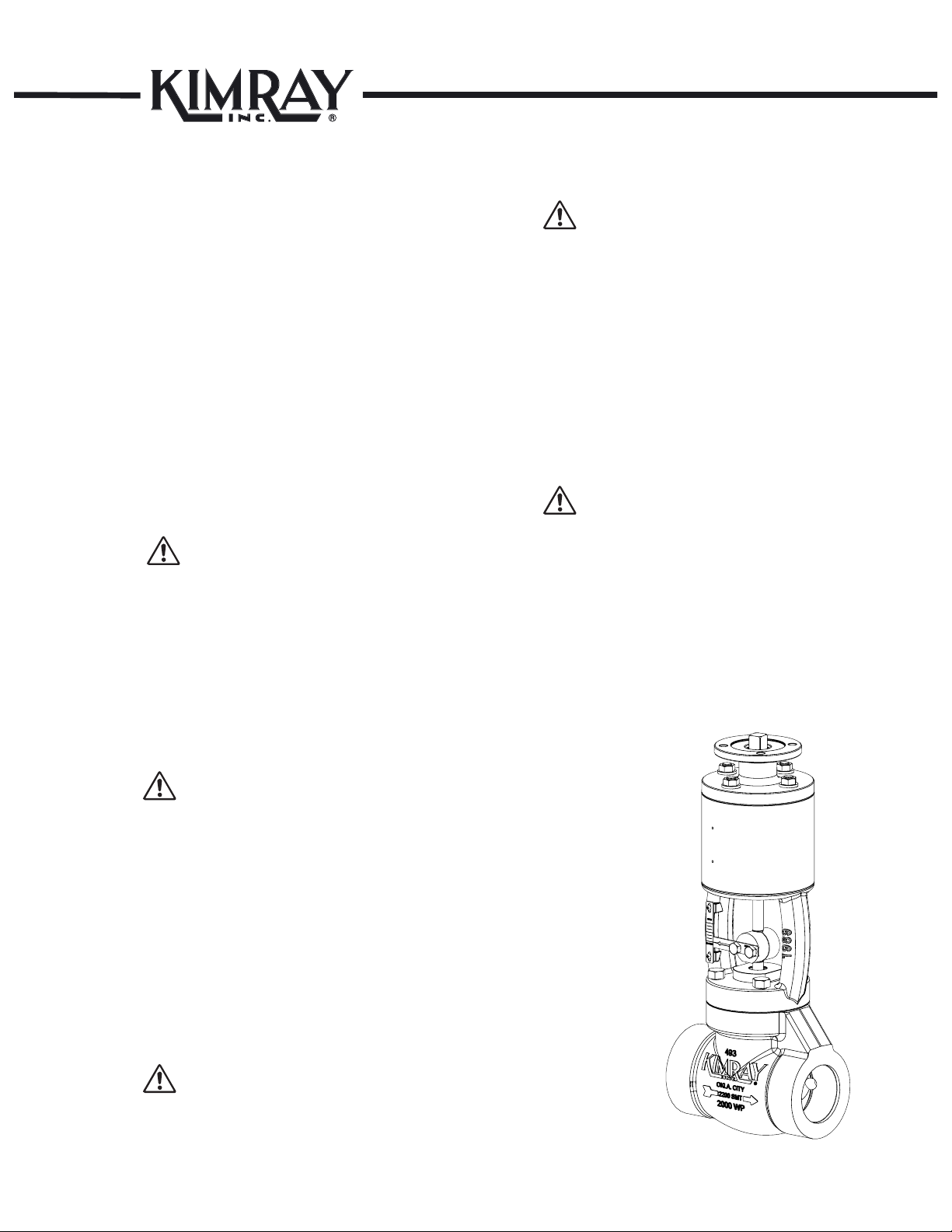
The Kimray R2L is used with Kimray High Pressure
Control Valves such as through or angle body valves. In
the R2L Actuator, the spiral rotation of the Rotary Shaft
by means of a rotary Actuator is translated into linear
motion, opening and closing the valve. The stroke length
is achieved with a 90° rotation of the shaft, clockwise to
close. As the Plug contacts the seat, a series of Springs
become loaded to ensure valve closure in the event of
seat creep or wear.
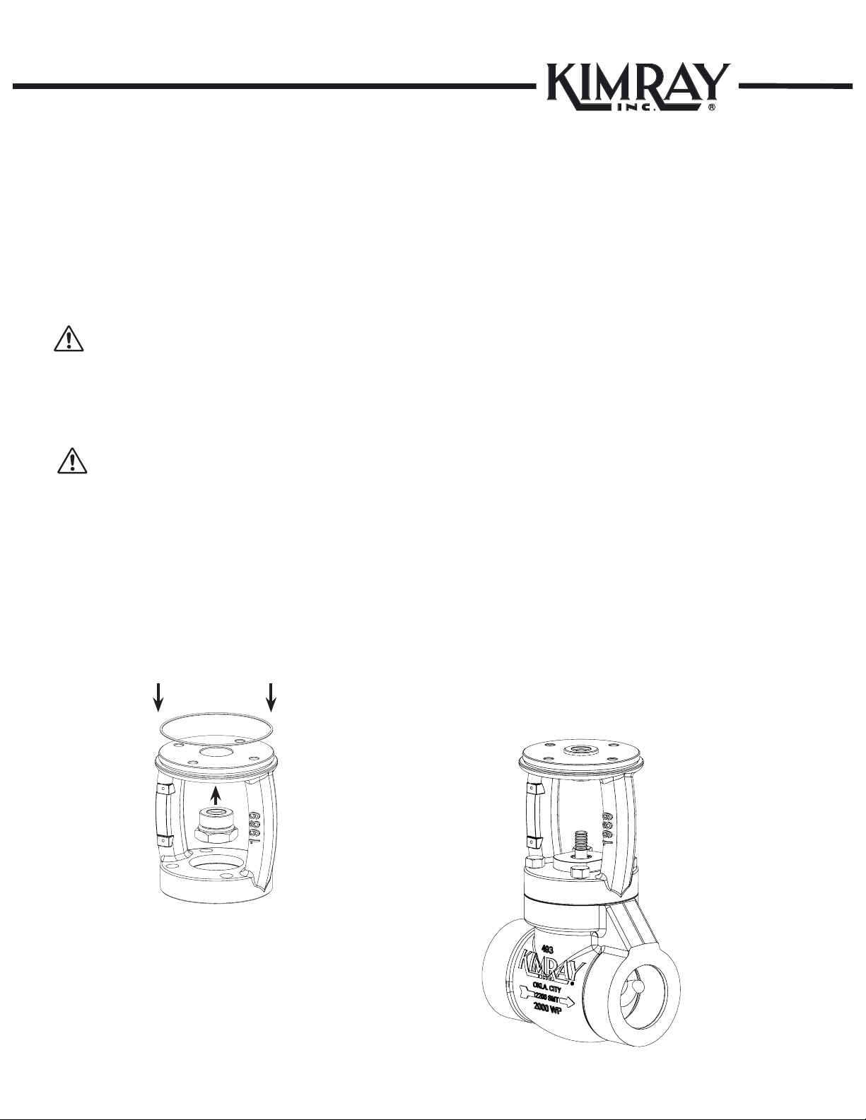
1. Mount the Actuator onto the Valve using supplied bolts
and tighten.
NOTE:
Tighten the bolts in a criss-cross pattern to avoid any miss
alignment. DO NOT OVER TIGHTEN. For 1in. and 2in.
tighten bolts from 25-30 ft/lbs torque.
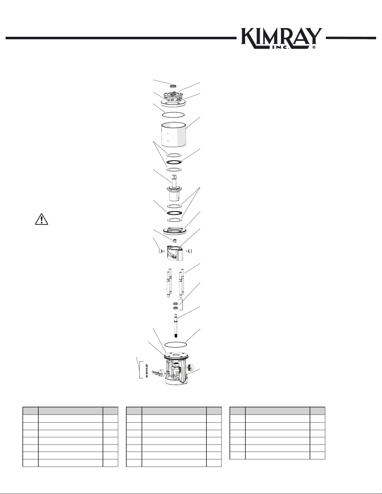
2. Install Travel Indicator Assembly on Stem and tighten
the bolts in the Coupling Block with a socket. Align
the open or close line on the Indicator Scale with
the Travel Indicator and secure the Indicator Scale by
driving in the u-drive screws. Adjust the Travel
Indicator as needed to ensure it does not catch or
drag against the Indicator Scale.
NOTE:
For the quarter turn Actuator, follow manufacturer
recommendation for the installation and operation notes.
3. Install the valve using good piping practice. For anged
bodies remove the masking sticker from the raised face of
each end connection & use a suitable gasket between the
body and the pipeline anges. For threaded (NPT) bodies,
use TFE Tape or pipe thread sealant on external pipe
threads.
4. Install the valve using good piping practices. For
anged bodies use a suitable gasket between the
body and the pipeline anges. For threaded (NPT)
bodies, use TFE tape or pipe thread sealant on
external pipe threads. Use good practices.
NOTE:
Use good electrical wiring practices and consult with
electrican.
See Fig. 1-1
2Start-up & Test
WARNING:
Before any service, be certain that the valve is fully
isolated and that all pressure upstream and downstream
has been relieved. Use bypass valves or fully shut off
the process. Be sure that any operating or instrument
gas lines have been disconnected. Never assume that
a check valve is fully blocking the downstream line.
Never tighten any tting or the main connections to the
regulator while there is pressure on the line. A leaking
valve indicates that service is required. Failure to take the
valve out of service immediately may create a hazardous
condition.
Verify all pressure connections are tight before
pressurizing the system.
NOTE:
When a gasket seat is disturbed during disassembly a
new gasket should be installed during re-assembly to
ensure proper sealing.
Repair kits are available. See Section E1 of catalog or
the packing slip enclosed with each valve for the correct
repair kit numbers.
Fig. 1-1

www.kimray.com
HIGH PRESSURE CONTROL VALVEHIGH PRESSURE CONTROL VALVE
Model: R2L ACTUATOR
Installation, Operation & Maintenance Guide
Model: R2L ACTUATOR
Installation, Operation & Maintenance Guide
8
DISASSEMBLY
✴ Recommended spare parts and stocked as repair kits
Fig. 3-1
3Adjusting Screw Assembly
Remove outside O-Ring (Item 2).
Remove inside O-Ring (Item 1).
Remove Snap Ring (Item 6).
Remove Retainer (Item 5).
Remove Wiper (Item 4).
Tip:
Use Kimray replacement parts only.
Insert Wiper (Item 4).
Insert Retainer (Item 5).
Insert Snap Ring (Item 6).
Lightly grease inside O-Ring, roll into
groove of Lower Adjustment Screw (Item
1).
NOTE:
At this point, lightly grease the outside
O-Ring before install (Item 2).
Disassembly Assembly
Item Description Part No. Oty
1 O-Ring Nitrile 153 (1") 1
530 (2")
2 O-Ring Nitrile 491 (1") 1
537 (2")
3 Adjusting Screw 458 (1") 1
503 (2")
4 Wiper 480 (1") 1
527 (2")
5 Retainer Washer 486 (1") 1
528 (2")
6 Snap Ring 938 (1") 1
940 (2")
6
5
2
4
1
3
6
5
2
4
1
3
✴
✴
✴
✴
✴
✴
✴
✴

HIGH PRESSURE CONTROL VALVEHIGH PRESSURE CONTROL VALVE
Model: R2L ACTUATOR
Installation, Operation & Maintenance Guide
Model: R2L ACTUATOR
Installation, Operation & Maintenance Guide
9
www.kimray.com
INSPECTION
4 Inspection & Cleaning
NOTE:
Check Cam Followers and Stem Carrier for excessive
wear.
Inspect:
If Thrust Bearings are dry, apply grease or
replace if necessary.

www.kimray.com
HIGH PRESSURE CONTROL VALVEHIGH PRESSURE CONTROL VALVE
Model: R2L ACTUATOR
Installation, Operation & Maintenance Guide
Model: R2L ACTUATOR
Installation, Operation & Maintenance Guide
10
ASSEMBLY
5 Mounting Yoke, Adjustment Screw,
O-Ring
Hand start the Lower Adjustment Screw into the Mounting
Yoke, lightly grease O-Ring before placing onto Mounting
Yoke O-Ring groove. See Fig. 5-1
NOTE:
Flip Mounting Yoke over and use a 7/8 in. socket for a 1
in. and use a 1 3/8 in. socket for a 2 in. to tighten.
Place Mounting Yoke upright onto Bottom Works.
See Fig. 5-2
NOTE:
Tighten the bolts in a criss-cross pattern to avoid any miss
alignment. DO NOT OVER TIGHTEN. For 1 in. and 2 in.
tighten bolts from 25-30 ft/lbs torque. See Fig. 5-2
Fig. 5-2
Fig. 5-1

HIGH PRESSURE CONTROL VALVEHIGH PRESSURE CONTROL VALVE
Model: R2L ACTUATOR
Installation, Operation & Maintenance Guide
Model: R2L ACTUATOR
Installation, Operation & Maintenance Guide
11
www.kimray.com
Install Stem into Adjustment Screw.
For 2 in. (four required), stack two Disc Spring onto Stem
with conical side down. Stack the other two onto the
Stem opposing the other two.
For 1 in. (three required), Stack Disc Spring in series onto
Stem starting with conical side down. place next Spring
Disc with conical side up. Place third Spring Disc with
conical side down.
ASSEMBLY
6 Spring Disc, Stem, Guide Rods,
Stem Carrier
Fig. 6-1 Fig. 6-2
Hand start the Guide Rods into Yoke. DO NOT tighten
fully.
Place Stem Carrier onto Guide Rods.
See Fig. 6-1 & Fig. 6-2
Thread Lock Nut onto Stem.
NOTE:
Use a 1/4 in. open ended wrench for 1 in. and 5/16 in.
open ended wrench for 2 in. or adjustable wrench.
Use wrench ats to tighten.
Ensure assembly moves smoothly before and after
tightening Guide Rods.

www.kimray.com
HIGH PRESSURE CONTROL VALVEHIGH PRESSURE CONTROL VALVE
Model: R2L ACTUATOR
Installation, Operation & Maintenance Guide
Model: R2L ACTUATOR
Installation, Operation & Maintenance Guide
12
ASSEMBLY
7 Bearing Support
Place Bearing Support onto Guide Rods.
See Fig. 7-1
Fig. 7-1

HIGH PRESSURE CONTROL VALVEHIGH PRESSURE CONTROL VALVE
Model: R2L ACTUATOR
Installation, Operation & Maintenance Guide
Model: R2L ACTUATOR
Installation, Operation & Maintenance Guide
13
www.kimray.com
ASSEMBLY
Fig. 8-1
NOTE:
Lightly grease both sides of Thrust Bearing thoroughly.
8 Race Bearing, Thrust Bearing,
Rotary Shaft & Cam Followers Place Race onto Bearing Support followed by Thrust
Bearing and another Race onto Thrust Bearing.
See Fig. 8-1
Place Rotary Shaft into Bearing Support. Place another
Race on top of Rotary Shaft and place Bearing and an-
other Race onto Thrust Bearing. Locate thread holes on
Rotary Shaft. Prime and place one drop of red Loctite™
onto threads of Cam Followers. Align holes of Rotary
Shaft with opening in Stem Carrier and thread Cam Fol-
lowers into Rotary Shaft. See Fig. 8-2.
NOTE:
Tighten Cam Followers to 20 in/lbs torque for 1in., tighten
the 2in. to 55 in/lbs with an 1/8in. allen wrench for both
sizes.
Fig. 8-2
Kimray recommends the use
of Loctite™ 7649 primer
and red Loctite™ 262.
Race
Bearing
Race
Rotary Shaft
Thrust Bearing
Bearing Support
Race
Rotary Shaft
Cam Follower
Stem Carrier

www.kimray.com
HIGH PRESSURE CONTROL VALVEHIGH PRESSURE CONTROL VALVE
Model: R2L ACTUATOR
Installation, Operation & Maintenance Guide
Model: R2L ACTUATOR
Installation, Operation & Maintenance Guide
14
ASSEMBLY
Slide Dust Cover onto assembly.
Install O-Ring onto Bearing Support.
See Fig. 9-1
Install Rod Wiper into top side of Flange Adapter.
Install Flange Adapter onto assembly. Ensure O-Ring is
not pinched. See Fig. 9-2
NOTE:
Kimray recommends using O-Ring pick.
Thread Lock Nuts onto Guide Rods and tighten with
wrench.
Install Indicator Scale on Yoke assembly and Coupling
Block and Pointer on Stem.
Install Travel Indicator Assembly on Stem. See Fig. 9-3
9 Cover, Flange Adapter, Rod Wiper
Fig. 9-1 Fig. 9-3
Fig. 9-2
10 Serial Tag
Lightly tap drive screws with small hammer. Leave tag
slightly loose until remaining drive screws are in place.
Then tap the screws tight against the tag.
Flange Adapter
Rod Wiper
Flange Adapter
Lock Nuts
Dust Cover
Yoke
O-Ring
Dust Cover

HIGH PRESSURE CONTROL VALVEHIGH PRESSURE CONTROL VALVE
Model: R2L ACTUATOR
Installation, Operation & Maintenance Guide
Model: R2L ACTUATOR
Installation, Operation & Maintenance Guide
15
www.kimray.com
TESTING
NOTE:
Use an open ended wrench to ensure assembly functions
properly without binding.
11 Actuator Test

www.kimray.com
HIGH PRESSURE CONTROL VALVEHIGH PRESSURE CONTROL VALVE
Model: R2L ACTUATOR
Installation, Operation & Maintenance Guide
Model: R2L ACTUATOR
Installation, Operation & Maintenance Guide
16
Page left blank

‡ Configuration of Back Pressure Valve is a trademark of Kimray, Inc.
Kimray is an ISO 9001- certied manufacturer.
Kimray quality assurance process maintains strict controls
of materials and the certication of parts used in the Kimray R2L actuator.
Please visit our website for up to date product data www.Kimray.com
HIGH PRESSURE CONTROL VALVEHIGH PRESSURE CONTROL VALVE
Model: R2L ACTUATOR
Installation, Operation & Maintenance Guide
Model: R2L ACTUATOR
Installation, Operation & Maintenance Guide

Kimray.com
© 2015 Kimray Inc., RM:0009
Issued 3/23
Other manuals for R2L
1
Table of contents
Other Kimray Control Unit manuals
Popular Control Unit manuals by other brands

Acromag
Acromag BusWorks XT Series user manual

Edwards
Edwards GSA-CC1 Installation sheet

Texas Instruments
Texas Instruments bq34210-Q1 Technical reference manual

wattwatchers
wattwatchers FBC-HC Installation and operating instruction

Warren rupp
Warren rupp Sandpiper HD20F Service & operating manual

Parker
Parker C2 Series Installation & service instructions