kinetic Viper 2 User manual

INSTRUCTIONS
VIPER2HIGH SPEED HANDPIECE
INSTALLATION AND OPERATION
The Viper2360 swivel handpiece is equipped with a quick connect feature to
facilitate fast connection of additional Kinetic Viper2360 handpieces as well as
easy lubrication and infection control procedures. To disassemble the
handpiece at the 360 quick coupling, simply pull the connecting ring towards the
tubing assembly. To reassemble, seat the handpiece onto the coupling until the
connecting ring automatically locks the handpiece in place.
IMPORTANT FOR SAFETY!
Never pull the connecting ring while the handpiece is turning to avoid the
danger of the handpiece being forcibly disengaged by the air pressure. Before
installing the handpiece, clean and lubricate as explained under
MAINTENANCEAND SERVICING procedures.
Before connecting the handpiece to the light source illumination system tubing,
install a Kinetic swivel lamp module (as shown) into the receptacle on the end
of the tubing. Be certain to align electrical pins to prevent breakage.
Connect the handpiece to the tubing being careful to align all air and water
tubes.
For maximum performance and bearing life, the Viper2360 handpiece should
be operated with clean, filtered, moisture-free air at a pressure of 38-43 psi as
measured at the handpiece coupling.
IMPORTANT OPERATING INFORMATION
1.Bur changing technique may be different than similar handpieces ... follow
instructions to avoid turbine damage.
2.Do not operate the handpiece at pressures in excess of 45 psi to avoid
premature turbine failure.
3.Never pull the 360 Quick Coupling connecting ring while the handpiece
is operating.
4.Never operate the handpiece, even for an instant, without a bur installed to
avoid chuck damage.
5.Avoid prolonged "no load" conditions.
6.When switching handpiece delivery hoses, insure that the recommended air
pressure is not exceeded.
7.Lubricate the handpiece at least twice a day.
8.Never use short shank burs.
CHANGING BUR
The Viper2chucking mechanism is designed to always be operated with a bur
installed. To prevent damage to the handpiece and the danger of an ejected
rotating bur, NEVER depress the PUSH-LOK while the handpiece is rotating.
Aflat wound spring is used to lock the bur jaws in place. When removing a bur,
be sure to depress the push button all the way down. A click may be felt as the
spring is compressed. This is especially important since, under certain heavy
cutting situations, the bur may afterwards seem to be "jammed" in the
handpiece. This is not a defect in the chuck mechanism but is a result of the
increased locking action of the bur jaws under heavy pressure.
The chuck is designed to become tighter as greater pressure is applied,
preventing bur slippage. If this situation is encountered, extra force can be
applied to the push button.
CHUCK MAINTENANCE
In general, the chuck mechanism is not subject to wear and should easily
outlast the turbine and bearing assemblies. However, inadvertent introduction of
oral cavity fluids, chemical disinfecting liquids, or other materials into the chuck
mechanism may possibly produce residues which could easily interfere with the
chucking action. If this situation is encountered and cannot be rectified by
cleaning, the turbine should be returned to the factory for disassembly, cleaning
and possibly a complete rebuilding.
LAMP CHANGING
Using the quick disconnect, remove the handpiece. Holding the smooth front of
the coupling, unscrew the tubing nut and separate the coupling from the tubing.
Unplug the burned out lamp and replace with a new Viper2360 swivel lamp
while carefully aligning the electrical pins. Replace the coupling onto the tubing
assembly and reconnect the handpiece.
INFECTION CONTROL PROCEDURES
AUTOCLAVE: To use an autoclave as an effective means of infection control
requires an autoclave cycle after each patient. Although the Viper2360
handplece is fully autoclavable, the autoclave environment is hostile to any
handpiece and will result in slow physical and operational degradation. Less
frequent autoclaving is not recommended since this would compromise
infection control. If autoclaving is the preferred method, the following directions
should be applied to assure maximum longevity:
1.Thoroughly clean handpiece using brush and detergent.
2.Rinse completely.
3.Allow handpiece to dry and then lubricate (optional).
4.Remove all excess lubricant.
DISINFECTANT SOLUTIONS: Various bactericidal and virucidal solutions are
available which provide high level disinfection and sterilization. In addition to
following the manufacturer's recommendations for use, it is essential to develop
a procedure to remove the solutions after disinfecting. The residues that remain
after evaporation of the solution can easily interfere with all mechanisms in the
handpiece. Do not allow the disinfectant solution to dry on the handpiece. If the
procedures suggest drying, modify them by soaking gauze in the solution and
leave it in contact with the handpiece for the required time duration.
Immediately after disinfecting, wash the handpiece thoroughly with tap water or
sterile water. Complete immersion in water will not harm the handpiece. After
washing, shake the handpiece to remove excess water, blow dry with Triplex
syringe and lubricate.
CHEMICLAVE: Chemiclave may be used for infection control as long as there
are not high levels of residue left on the handpiece after the cycle. Be certain
the chemiclave solution used is compatible with those materials found in high
speed handpieces. A chemiclave is essentially an autoclave and therefore
follow all considerations underAUTOCLAVE.
DRY HEAT STERILIZATION: Do not use dry heat sterilizers for handpieces.
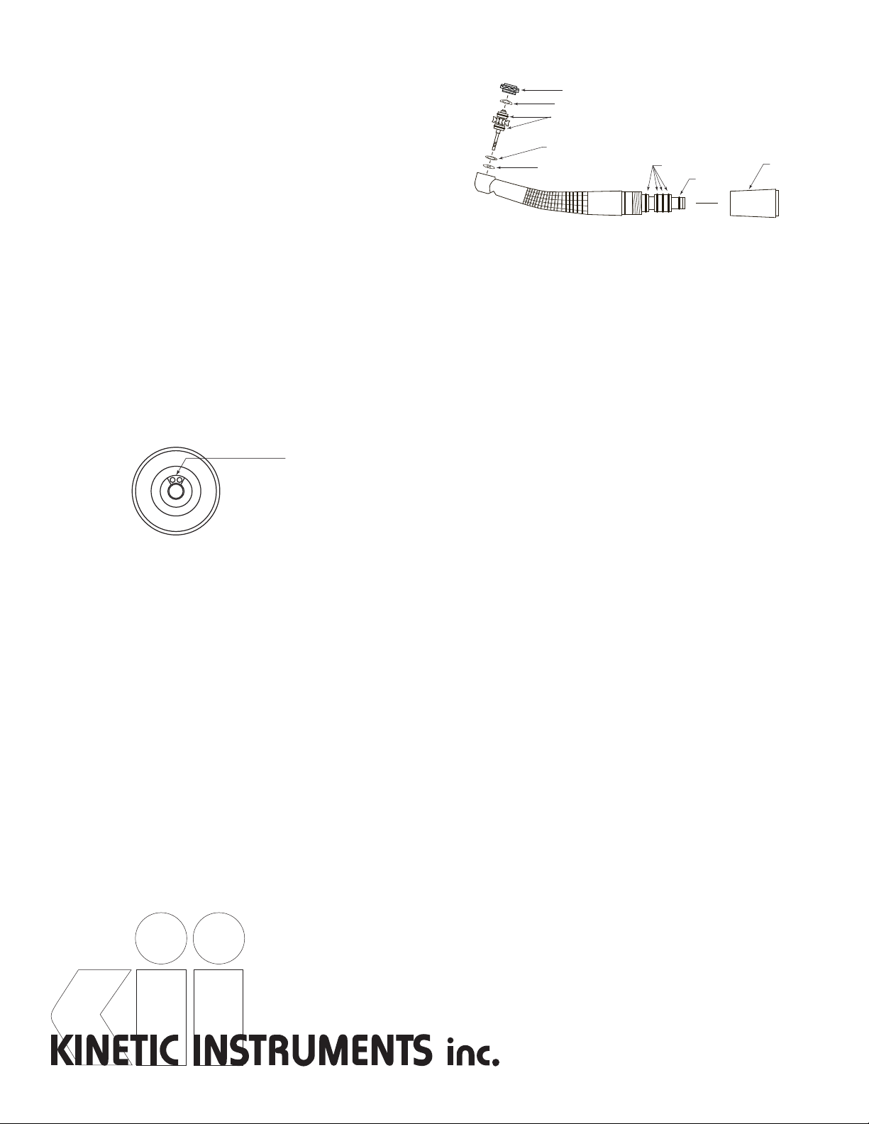
TURBINE CARTRIDGE REPLACEMENT
Remove bur from handpiece. Remove handpiece head back end cap using the
cap wrench as illustrated. Push out the turbine cartridge assembly from the
head cavity using a bur or bur blank if necessary.
Note: Although the assembly drawing shows the location of the dust sealing
washer, dust washer retainer and two turbine cartridge o-rings, it is not
recommended that these parts be replaced without prior experience. Therefore,
do not attempt to remove these parts. If unlikely damage has occurred, consult
the factory for further instructions.
Handpiece
Quick
Coupling
Hose
Nut
Lamp
Module
Connecting
Ring
2.

17 Berkshire Boulevard
Bethel, Connecticut 06801
Telephone:
Toll Free:
24hr Fax:
203-743-0080
800-233-2346
203-790-1227
Website: www.kineticinc.com
e-mail: [email protected]
Lube Here if Using
Squeeze Bottle
Viper 360 Lubricant
Supplied with the new turbine are two new turbine o-rings, one dust sealing
washer, one dust washer retainer and one wave washer. These parts should
only be installed by an experienced technician. Otherwise, remove these parts
and save them for a later time if required.
Install the new turbine by gently pushing the back of the turbine cartridge while
making sure that the front bushing is aligned with the front hole in the
handpiece head. Turbine will "snap-in" when the front bearing enters the seat
properly. Wiggling the turbine cartridge using the bur blank helps alignment into
the front bearing o-ring.
Insure that the spring wave washer and end cap o-ring are in their proper
position and replace the end cap. Tighten securely using the cap wrench.
Turn the bur blank by hand and feel for free rotational movement of the turbine.
If the rotation feels tight or "scratchy", disassemble and re-install the turbine.
MAINTENANCE AND SERVICING
LUBRICATION: To provide maximum performance and bearing life, the
handpiece should be lubricated twice a day. When the handpiece is used for
more than 30 minutes continuously, intermediate lubrication is recommended.
To lubricate, disconnect the handpiece at the 360 Quick Coupling and insert 3 -
4 drops of oil into the two drive air holes on the swivel shaft as shown. If Viper
Spray lubricant is used, insert the handpiece into the spray adapter as shown in
the diagram on the spray can. Operate the spray can in an upright position for
approximately 1 second.
Replace the handpiece and activate the drive air for a few seconds to distribute
the lubricant throughout the turbine and remove debris and old oil. Use only
appropriate high speed handpiece lubricants. Any other lubricants may cause
bearing damage with resultant premature turbine failure. Viper 360 high speed
spray lube or bottle lube is recommended for maximum effectiveness.
CLEANING WATER PORTS: The Viper2handpiece employs a triple port water
spray system to provide maximum cooling. Depending on the water supply, the
water spray tubes may become clogged with mineral deposits from the water. It
may be possible to use very fine pieces of wire to dislodge foreign material from
the tiny water ports. However, attempting this is rarely effective. Return to the
factory for repair.
CLEANING FIBER OPTICS: Oil or dirt which gets on the fiber optic may reduce
the brightness of the handpiece or discolor the light. Disassemble the
handpiece at the 360 quick coupling and clean the fiber optic at the back and
the front, near the bur, with alcohol on a cotton applicator stick. Remove any
remaining residue. If the residue cannot be removed with alcohol, that may
indicate permanent damage. Return to the factory for evaluation.
O-RING REPLACEMENT: If it is suspected that the swivel o-rings have worn,
replace all five o-rings as follows:
Disconnect the handpiece from the 360 Quick Coupling. Unscrew the swivel
cover (identified by the Viper2 logo and serial number) from the back of the
handpiece. Lift and remove the worn o-rings with an explorer or cotton pliers.
Replace with new o-rings being careful to slide them into position with gentle
finger pressure. Lightly lubricate o-rings with handpiece oil.
Replace the swivel cover on the handpiece and hand tighten to prevent air
and/or water leaks.
IMPORTANT!: Use only Viper2360 o-rings. Other o-rings will not be the proper
size or durometer and will interfere with the operation of the handpiece and/or
the swivel mechanism.
ASSEMBLY DETAIL
OPTIONAL HANDPIECE CONNECTIONS
In addition to the standard Kinetic 360 swivel style back end tubing connection,
Viper2is also available in various optional configurations that can be used to
adapt to or connect directly to other styles of existing tubings that have been
manufactured by Kinetic Instruments as well as others.
One common tubing configuration currently employed and highly popular is the
6-pin or ISO-C connection. In this case, an adaptor is available that attaches to
the ISO-C tubing and permits the connection of the Kinetic Viper2360 swivel
quick connect coupler. When using this adaptor it is important to remember to
set the lamp voltage correctly.
Also available is an entirely different back end configuration that is designed to
permit the Viper2to be compatible with manufacturers of unique styles that
utilize a tubing assembly with a dedicated connector that cannot be removed.
Generally, these tubing assemblies differ considerably and require the utilization
of specialized connections. Most, if not all, of these styles are carried by Kinetic
Instruments. When a situation such as this is encountered, it is advisable to
speak directly with one of our handpiece specialists to insure that the
connection is the most convenient and least expensive.
Another possibility is a tubing assembly that uses the older and still available 5-
hole or ISO-B connection. Very early versions of this assembly employed a
large light generation box that produced illumination via actual glass fibers that
were contained in the center of the tubing.Although it is strongly recommended
that the entire system be replaced, an adaptor is available for this scenario as
well.
Kinetic Instruments, from the late 1970's, continues to highly specialize in the
development of handpiece connections and is able to provide expert assistance
for any application.
MANUFACTURING WARRANTY
Kinetic Instruments warrants this product to be free of manufacturing defects
for a period of six months from date of purchase. Kinetic lnstruments will repair
or replace free of charge any defective parts during that time, provided that
such defects occurred during normal use, and, at our discretion, such parts
were properly installed and were not subject to abuse, misuse or accident. This
warranty was made expressly in place of all other warranties or guarantees,
express or implied, with respect to quality, merchantability or fitness for a
particular purpose.
CORPORATE CONTACT INFORMATION
Kinetic Instruments maintains a principal headquarters for customer support
and selected manufacturing located in Bethel, Connecticut, U.S.A. This office
receives telephone calls Monday to Friday, 9 am to 5 pm EST (Eastern Time).
Mailing address:Telephone (local): 203-743-0080
Kinetic Instruments Inc.Telephone (toll free): 800-233-2346
17 Berkshire Blvd.Fax (24 hours, 7 days): 203-790-1227
Bethel, CT 06801
Internet website: www.kineticinc.com
Back End Cap
Large O-rings (4 pieces)
Small O-ring
Turbine O-rings
(2 Pieces)
Dust Washer Retainer
Dust Sealing Washer Swivel Cover
Spring Wave Washer
Popular Medical Equipment manuals by other brands

Unicare Health
Unicare Health Seahorse Sanichair Instruction & safety manual

RxPerfect
RxPerfect TimeCap & Bottle user guide

Arjo
Arjo Maxi 500 Instructions for use

SKEEPER
SKEEPER Mozart Manual instruction

Omron
Omron Comp Air Elite NE-C30-E instruction manual

illumina
illumina NextSeq 550Dx Instrument Safety and Compliance Guide