King Tony 9DM1371 User manual

Enjoy your work
AUTORANGING DIGITAL MULTIMETER
INSTRUCTION MANUAL
NO.9DM1371

21
EN
FR
ES
EN
FR
ES
CONTENTS
TITLE PAGE
SAFETY INFORMATION................................ 1
FEATURES..................................................... 2
1.SPECIFICATIONS....................................... 3
1-1 General information............................. 3
1-2 Electrical specications..........
.............
7
2.PARTS & CONTROLS...
............................
10
2-1 Name of parts and positions
...............
10
2-2 Operating Instruction
......
..................... 14
2-2-1 Scale ranging
......
............................. 14
2-2-2 DC Voltage measurement
................
14
2-2-3 AC Voltage measurement
................
15
2-2-4 AC/DC Current measurement
..........
16
2-2-5 Diode Test
......
.................................. 17
2-2-6 Resistance measurement
................
18
2-2-7 Continuity measurement
..................
19
2-2-8 Frequency measurement
.................
20
3.BATTERY & FUSE REPLACEMENT
.........
21
3-1 Battery check & replacement
..............
21
3-2 FUSE replacement
......
........................ 22
4.MAINTENANCE
......
.................................... 23
Read First : Safety Information
• Never use the meter if the meter or test leads
look damaged.
• Be sure the test leads and switch are in the
correct position for the desired measurement.
• Never measure resistance or testing acoustic
continuity in a circuit when power is applied.
• Never connect the probe to a voltage source
when the test leads are plugged into the 10 A
input jack .
• Never connect the probe to a voltage source
when the function are in uA or mA range.
• Never apply more than rated voltage between
any input jack and earth ground.
• Be careful when working with voltages above
60 V DC or 30 V AC rms. Such voltages pose a
shock hazard.

23
EN
FR
ES
EN
FR
ES
• Keep your ngers behind the nger guards on
the test probes when making measurements.
• To avoid false readings, replace the battery
immediately, When symbol appears.
Symbols:
Read Safety Information First
Dangerous Voltage May Be Present
Meter is protected throughout by double
insulation or reinforced insulation.
When servicing, use only specied replacement parts.
Comply with IEC1010-1 CAT II
1. SPECIFICATIONS
1-1 General information
Environment conditions:
Maintenance & Clearing:
Display:
• Installation Categories II
• Pollution Degree 2
• Altitude up to 2000 meters
• Indoor use only
• Relatively humidity: 80% max.
• Operation Ambient temp: 0~40°C
• Repairs or servicing not covered in this
manualshouldonlybyqualiedpersonal.
• Periodically wipe the case with a dry cloth and
detergent. Do not use abrasives or solvents
on this instrument.
• Digital: 4000 counts
• Analog: 42 segments

45
EN
FR
ES
EN
FR
ES
Display Symbol Denition :
Low
Battery
AC Symbol
DC Symbol
Manual Range
Bargraph Indication
Relative
Reading
Data
Hold
Continuity
Beeper Diode
Low Battery
Auto Range
Relative Reading
Data Hold
Maximum Value
Minimum Value
Continuity Beeper
Diode
Alternating current or voltage
Direct current or voltage
Negative polarity
Manual Range
Bargraph indication
Frequency
Voltage
Millvolt ( 1 X 10⁻³ volt)
Ampere (amps) Current
Microampere ( 1 X 10⁻⁶ amp)
Milliampere ( 1 X 10⁻³ amp)
Ohm. Resistance
Kilohm ( 1 X 10³ohm). Resistance
Megohm ( 1X 10⁶ohm). Resistance

67
EN
FR
ES
EN
FR
ES
Sampling Rate:
Digital: 2 times/sec
Analog: 20times/sec for Bargraph indication.
Over Range Indication: LCD will show “OL”.
Low Battery Indication:
The is displayed when the battery voltage
drop below the proper operating range.
Battery type: 1.5V.SIZE AAA Battery
Battery Life: 500hrs typical (alkaline Battery)
Polarity: ” ” Indicates negative input.
Auto Power Off Time: 30 minutes
Operating Temperature and Humidity:
0°C to 40°C (32°F to 104°F) below 80% RH
Storage Temperature and Humidity:
-10°C to 60°C (14°F to 140°F) below 70% RH
Temperature Coefcient:
0.1 x ( Specied accuracy ) / °C (<18°C or >28°C)
Weight: Approx.220g (7.76oz)
Dimensions (L×W×H):
150mm×72mm×35mm (5.9”×2.83”×1.38”)
Accessories:
Test leads, Spare fuse (0.5A/250V), Batteries
and Instruction manual.
Electromagnetic / Compatibility:
Vac and Aac only: RF eld = 3V/m
Total accuracy = specied accuracy+2.0% of range
Safety:
600V CAT II Regulation EN61010; Part 1: 1993
Certication:
1-2 Electrical Specications
Accurace specication:
±([… %of reading]+ […number of least signicant
digits]) at 18°C to 28°C ( 64°F to 82°F ) 80%RH
Diode Tester
Continuity Beeper
DC Voltage (Auto Range)
Range Resolution Accuracy Test
Current
Test
Voltage
Overload
Protection
1mV 1%+2 <1mA <3.2V 600V rms
Range Active Range Test Voltage Overload Protection
Under40Ω <1.5V 600V rms
Range Resolution Accuracy Input Impedance Overload
Protection
400mV 0.1mV 0.5%+2 >1000MΩ 750V rms
4V 1mV 0.5%+2 11MΩ 750V rms
40V 10mV 0.5%+2 10MΩ 750V rms
400V 100mV 0.5%+2 10MΩ 750V rms
600V 1V 0.8%+2 10MΩ 750V rms

89
EN
FR
ES
EN
FR
ES
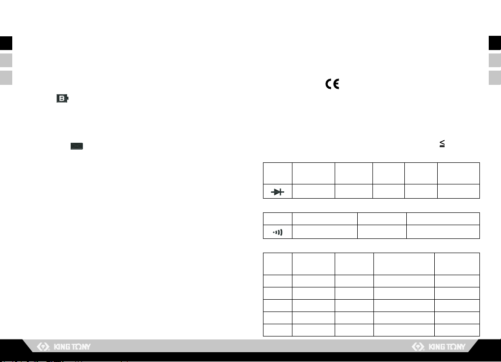
AC Voltage ( Auto Range)
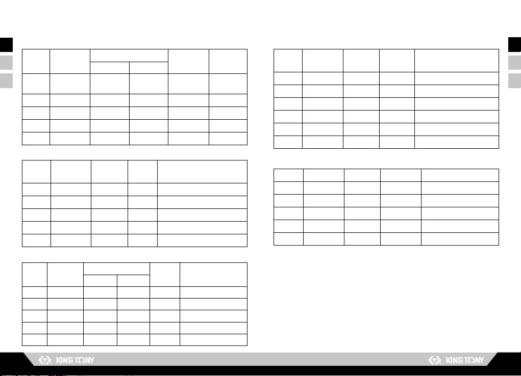
AC Current(uA,mA,Auto Range)
DC Current (uA,mA,Auto Range)
Ohms (Auto Range)
Frequency (Auto Range)
Range Resolution Accuracy
Input
Impedance
Overload
Protection
45Hz~400Hz 400Hz~1KHz
400mV 0.1mV 1%+5
(45Hz~100Hz) >1000MΩ 750V rms
4V 1mV 1%+4 1.5%+4 11MΩ 750V rms
40V 10mV 1%+4 1.2%+4 10MΩ 750V rms
400V 100mV 1%+4 1.2%+4 10MΩ 750V rms
600V 1V 1%+4 1.2%+4 10MΩ 750V rms
Range Resolution Accuracy
Burden
Voltage Overload Protection
45Hz~500Hz 500Hz~1KHz
400uA 0.1uA 1.3%+5 1.6%+5 <0.25V rms 0.5A / 250V Fast Blow Fuse
4000uA 1uA 1.3%+5 1.6%+5 <1V rms 0.5A / 250V Fast Blow Fuse
40mA 10uA 1.3%+5 1.6%+5 <0.25V rms 0.5A / 250V Fast Blow Fuse
400mA 100uA 1.3%+5 1.6%+5 <1.5V rms 0.5A / 250V Fast Blow Fuse
10A 10mA 1.5%+5 1.8%+5 <0.35V rms 10A / 250V Fast Blow Fuse
Range Resolution Accuracy Burden
Voltage Overload Protection
400uA 0.1uA 1%+2 <0.25V 0.5A / 250V Fast Blow Fuse
4000uA 1uA 1%+2 <1V 0.5A / 250V Fast Blow Fuse
40mA 10uA 1%+2 <0.25V 0.5A / 250V Fast Blow Fuse
400mA 100uA 1%+2 <1.5V 0.5A / 250V Fast Blow Fuse
10A 10mA 1.2%+2 0.35V 10A / 250V Fast Blow Fuse
Range Resolution Accuracy Test
Voltage Overload Protection
400Ω 0.1Ω 0.75%+2 <1.5V DC 600V rms
4KΩ 1Ω 0.75%+2 <1.5V DC 600V rms
40KΩ 10Ω 0.75%+2 <1.5V DC 600V rms
400KΩ 100Ω 0.75%+2 <1.5V DC 600V rms
4MΩ 1KΩ 0.75%+2 <1.5V DC 600V rms
40MΩ 10KΩ 0.75%+3 <1.5V DC 600V rms
Range Resolution Accuracy Sensitivity Overload Protection
4KHz 1Hz 0.1%+1 <300mV pp 600V rms
40KHz 10Hz 0.1%+1 <300mV pp 600V rms
400KHz 100Hz 0.1%+1 <300mV pp 600V rms
4MHz 1KHz 0.1%+1 <3V pp 600V rms
40MHz 10KHz 0.1%+1 <3V pp 600V rms

10 11
EN
FR
ES
EN
FR
ES
V
A
VA A
A
A
V
A
A
AV
A V
A
VA
2. PARTS & CONTROLS
2-1 Name of parts and position
LCD Display:
Measured values, unit, function and decimal
points symbols are displayed.
Relative Button:
Press button to enter the relative mode. The
Display is zeroed , and the reading is stored as
reference value for subsequent measurements. Press it
again, the “ ” annunciator blinking and stored relative
value will display . Press and hold down button for
1 second to exit the relative mode.
Auto-range & Manual Range Button:
• Press to select the Manual Range mode and the
annunciator turn on and The meter remains in the same
range it was.
• In the Manual Range mode, each time you press
button, the range (and the input range annunciate)
increases, and a new value is displayed.
• If the meter is in the highest range, the next range is
change to the lowest range. To exit the Manual Range
mode and return to Auto Range mode, Press and hold
down for 1 seconds, the AUTO annunciate turns
back on.
1
2
3

12 13
EN
FR
ES
EN
FR
ES
MAX/MIN recording button:
Press button to enter the maximum and minimum
recording mode, select the proper range before using
MAX/MIN to ensure that reading value will not exceed
the measurement range. Press the button once to select
MAX value.
Press it again to select MIN value, and press again to
select current value with annunciator blinking.
Press and hold down button for 1 second to exit
the MAX MIN mode.
AC/DC Current Select and / Ω Select Button:
• To select function AC or DC in current Ampere range.
• To select continuity measurements or Resistance
measurement at / Ωrange.
Function Selector Switch:
For power OFF and selection of desired Function
Range.
Tilt stand:
10A Measuring Connector:
To connect positive lead (red test lead)for current
measurement below 10A.
VΩ,μA, mA, Hz, Measuring Connector:
To connect positive lead ( red test lead ) for voltage,
diode, frequency, microampere, milliampere and
continuity measurement.
Note:
To avoid blowing an input fuse, use the 10 A jack
until you are sure that the current is less than
400mA. When Doing Current Measurement.
COM Measuring Connector:
To connect negative lead (black test lead) for voltage,
frequency, current, resistance, diode and continuity
measurement.
4
5
6
MAX
MIN
MAX
MIN
MAX
MIN
7
8
9
MAX
MIN

14 15
EN
FR
ES
EN
FR
ES
2-2 Name of parts and position
2-2-1 Ranging
2-2-2 DC Voltage Measurements
2-2-3 AC Voltage Measurements
The meter defaults to autorange mode when you
turn on the Meter. Manual ranging is available in
V , V , ohms , A , A , frequency.
To return to autorange, press for 1 second
or turn the rotary switch.
Connect red test lead to “ V ” jack and black test lead to “ COM ” jack.
Set Range Switch to V range.
Connect the test leads IN PARALLEL to the circuit being measured.
Read the Voltage value on LCD.
Connect red test lead to “ V ” jack and black test lead to “ COM ” jack.
Set Range Switch to V range.
Connect the test leads IN PARALLEL to the circuit being measured.
Read the Voltage value on LCD.
WARNING
WARNING
Maximum Input Voltage is 600V AC/DC.Do not attempt to Take
any voltage measurement that may exceed to avoid Electrical
shock hazard and/or damage to this instrument.
Maximum Input Voltage is 600V AC/DC. Do not attempt to Take
any voltage measurement that may exceed to avoid Electrical
shock hazard and/or damage to this instrument.
1
1
2
2
3
3
4
4

16 17
EN
FR
ES
EN
FR
ES
2-2-4 AC/DC Current Measurements 2-2-5 Diode Tests
Connect red test lead to the “mA / uA ”jack for Current measurements
up to 400mA.( For measuring Current between 400mA to 10A ,
Connect red test lead to “ 10 A ” jack ) Connect black test lead to“ COM
” jack.
Set Range selector Switch to desired A range and press DC/AC button
to select AC/DC function.
Cut the power to the circuit to be tested and Connect the instrument IN
SERIES with the circuit with the black test lead on the negative “ - ”side
and the red lead on the positive “ + ”side being measured.
Apply power and read the ampere value on LCD.
Connect red test lead to “ ” jack and black test lead to “COM ” jack.
Set Range selector Switch to “ ” range.
Connect the red test lead to the anode side and black test lead to the
cathode side of the diode being tested.
Read forward Voltage( Vf) value on LCD.
If the polarity of test leads are reversed with diode polarity , the
digital reading show “ OL ”.This can be used for distinguishing anode
and cathode terminal of a diode.
WARNING WARNING
To avoid injury, do not attempt a current measurement if the
open circuit voltage exceeds the rate voltage of the meter.
Before taking any in-circuit measurement, remove power from
the circuit being tested and discharge all capacitors in the
circuit.
uA . mA measurement Amp measurement
1
1
2
2
3
3
3
4
4
5

18 19
EN
FR
ES
EN
FR
ES
Connect red test lead to “ Ω” jack and black test lead to “COM ” jack.
Set Range Switch to “ ” range, by pressing button.
Remove power from the circuit being tested and discharge all
capacitors.
Connect test lead to the circuit being measured.
Whentheimpedancebetweenthetestjackislowerthan40Ω,itwill
activate a continuous beeper ( 2KHz).
2-2-6 Resistance Measurements
Connect red test lead to “
Ω
” jack and black test lead to “ COM ” jack.
Set Range Switch to “ Ω ” range and press button to “ Ω”
function.
Connect test lead to the circuit being measured and read the
resistance value on LCD.
WARNING
Before taking any in-circuit measurement, remove power from
the circuit being tested and discharge all capacitors in the
circuit.
1
2
3
2-2-7 Continuity Measurements
WARNING
Before taking any in-circuit measurement, remove power from
the circuit being tested and discharge all capacitors in the
circuit.
1
2
3
4
5
Note:
Continuity Test is available to check open/short of
the circuit.
Open circuit Short circuit

20 21
EN
FR
ES
EN
FR
ES
2-2-8 Frequency Measurements
Connect red test lead to “Hz” jack and black test lead to “COM” jack.
Set Range Switch to “Hz” range
Connect the test lead IN PARALLEL to the circuit being measured.
Read the frequency value on LCD.
1
2
3
4
3. BATTERY & FUSE REPLACEMENT
3-1 Battery Check & Replacement
1. Asbatterypowerisnotsufcient,LCDwilldisplay
“ ”. Replacement of two new batteries type AAA
1.5V is Required.
2. Set Range Switch to “ OFF ” position .Use a
screwdriver to remove the rear cover. Take out the
battery and replace them with two new batteries of
type AAA1.5V.
3. Place back the rear cover and secure it with the
original screw.
WARNING
To prevent electrical hazard or shock, turn off
multimeter and disconnect test leads before
removing back cover.

22 23
EN
FR
ES
EN
FR
ES
3-2 FUSE Replacement
1. Set Range Switch to “OFF” position. Use a
screwdriver to remove the rear cover. Take out the
malfunction fuse and replace it with a new fuse
rated 0.5A / 250V (or 10A / 250V) of fast blow type.
2. Place back the rear cover and secure it with the
original screw.
WARNING
For safety , use exact replacement
F1 : F0.5A / 250V 5 ×20 mm Fast blow type
F2 : F10A / 250V 6.3 ×32 mm Fast blow type
Batteries
0.5A fuse
10A fuse
Screw
Screw
4. MAINTENANCE
WARNING
CAUTION
To avoid electric shock, remove the test leads
before opening the case, and close the case
before using the meter.
To prevent re and possible arc-ash, use
fuses with ratings shown on the back of the
meter.
To avoid contamination or static damage, do
not touch the circuit board without proper
static protection.

24 25
EN
FR
ES
EN
FR
ES
SOMMAIRE
TITRE PAGE
CONDITIONS D’UTILISATION...................... 25
SYMBOLES.................................................... 26
1.CARACTÉRISTIQUES................................ 27
1-1 Informations générales........................ 27
1-2 Caractéristiques électriques...
.............
31
2.ELÉMENTS ET CONTRÔLES
....................
34
2-1 Nom des éléments et position
.............
34
2-2 Précautions d’utilisation
..
..................... 38
2-2-1 Choix de mesure.............................. 38
2-2-2 Mesure de tension DC.....
................
38
2-2-3 Mesure de tension AC......
................
39
2-2-4 Mesure d’intensité AC/DC......
..........
40
2-2-5 Vérication de diode
.
........................ 41
2-2-6 Mesure de résistance.......
................
42
2-2-7 Mesure de courant continu
..............
43
2-2-8 Mesure de fréquence......
.................
44
3.
REMPLACEMENT DES PILES ET FUSIBLES
45
3-1 Contôle et remplacement des piles
.....
45
3-2 Remplacement des fusibles................ 46
4.MAINTENANCE
......
.................................... 47
Lire d’abord les précautions
d’utilisations
• Ne jamais utiliser le multimètre si l’appareil ou
si les ls tests paraissent endommagés.
• Assurez-vous que les ls test et le
commutateur sont correctement installés pour
la mesure souhaitée.
• Ne mesurez jamais la résistance et ne testez
jamais la continuité acoustique sur un circuit
sous tension.
• Ne jamais connecter la sonde à une source de
tension quand les ls test sont reliés à la prise
10A .
• Ne jamais connecter la sonde à une source
quand la fonction est sur uA ou mA.
• Ne jamais appliquer plus que la tension
évaluée entre une prise et le sol.
• Faîtes attention quand vous travaillez avec des
tensions supérieures à 60V ou 30 V ac rms. De
telles tensions posent un risque d’électrocution.

26 27
EN
FR
ES
EN
FR
ES
• Gardez vos doigts derrière le protège doigt sur
les sondes quand vous effectuez une mesure.
• Pour éviter les mauvaises lectures, remplacez
les piles dès que l’icône apparaît.
1. CARACTÉRISTIQUES
1-1 Information générale
Conditions d’utilisation :
Entretien et nettoyage :
Afchage:
• Installation Catégorie II
• Degré de pollution 2
• Jusqu’à 2.000m d’altitude
• Utilisation en intérieure uniquement
• Taux d’humidité : 80% max
• Température ambiante : 0~40°C
• Les réparations et entretiens non traités dans
ce manuel doivent être effectuées par une
personne compétente.
• Nettoyer régulièrement l’appareil avec un
tissu propre et du détergent. Ne jamais utiliser
de produits abrasifs ou de solvants sur les
éléments.
• Digital : 4.000 données
• Analogique : 42 segments
Symboles:
Lire d’abord les précautions d’emploi
Tension dangereuse peut-être présente
Le multimètre est protégé par une double
isolation ou par une isolation renforcée.
Quand vous réparez l’appareil, n’utilisez que des pièces de rechanges agrées.
Comply with IEC1010-1 CAT II

28 29
EN
FR
ES
EN
FR
ES
Polarité négative
Mode manuel
Indications en barres
Fréquence
Tension
Milvolt ( 1 X 10⁻³ volt)
Ampère (amps)
Microampère (1 X10⁻⁶ amp)
Milliampère (1X10⁻³ amp)
Ohm. Résistance
Kilohm (1 X 10³ohm). Résistance
Megohm (1 X 10⁶ohm). Résistance
Dénition des symboles afchés :
Batterie
faible
Symbole AC
Symbole DC
Mode manuel
Indications en barres
Lecture
relative
Prise de
données
Sonnerie
continue Diode
Batterie faible
Mode automatique
Lecture relative
Prise de données
Valeur maximum
Valeur minimum
Sonnerie continue
Diode
Courant alternatif ou tension
Courant continu ou tension

30 31
EN
FR
ES
EN
FR
ES
Electromagnétique / Compatibilité:
Vac et Aac seulement : champ RF = 3V/m
Total exactitude = exactitude spéciée + 2.0% de la plage
Safety:
600V CAT II, Régulation EN6010 ; Part 1 : 1993
Certication:
1-2 Spécications électriques
spécication de précision :
+- ([..% de la mesure]+[ … nombre afché sur
l’écran]) de 18°C à 28°C et en dessous de 80% RH
Test de diode
Sonnerie continue
Tension DC (mode auto)
Plage Résolution Précision Test
d’intensité
Test de
tension Protection
1mV 1%+2 <1mA <3.2V 600V rms
Plage Plage active Test de tension Protection
Sous40Ω <1.5V 600V rms
Plage Résolution Précision Impédance
d'entrée Protection
400mV 0.1mV 0.5%+2 >1000MΩ 750V rms
4V 1mV 0.5%+2 11MΩ 750V rms
40V 10mV 0.5%+2 10MΩ 750V rms
400V 100mV 0.5%+2 10MΩ 750V rms
600V 1V 0.8%+2 10MΩ 750V rms
Cadence de mesurage :
Digital : 2 mesures / seconde
Analogique : 20 mesures / seconde
(indications en barres).
Indication ’’au dessus de la plage’’ : “OL”
s’afche sur l’écran.
Indication batterie faible :
L’icône s’afche quand la chute de tension
des piles est au-dessous de la plage de
fonctionnement appropriée.
Type de piles : 1.5V, type AAA
Durée de vie des piles : 500 heures environ
(alcalines)
Polarité : ” ” indique la polarité négative.
Mise en arrêt automatique : 30 minutes
Température et humidité de fonctionnement :
0°C à 40°C (32°F à 104°F), au dessous de 80%RH
Température et humidité de rangement :
-10°C à 60°C (14°F à 140°F), au dessous de 70%RH
Temperature Coefcient :
0.1 x ( Specied accuracy ) / °C (<18°C or >28°C)
Poids : 220g
Dimensions (L×l×H):
150mm×72mm×35mm (5.9”×2.83”×1.38”)
Accessories:
Fils test, fusible (0.5A/250V), piles et manuel
d’instruction.

32 33
EN
FR
ES
EN
FR
ES
Ohms (mode auto)
Fréquence (mode auto)
Plage Résolution Précision Test de
tension Protection
400Ω 0.1Ω 0.75%+2 <1.5V DC 600V rms
4KΩ 1Ω 0.75%+2 <1.5V DC 600V rms
40KΩ 10Ω 0.75%+2 <1.5V DC 600V rms
400KΩ 100Ω 0.75%+2 <1.5V DC 600V rms
4MΩ 1KΩ 0.75%+2 <1.5V DC 600V rms
40MΩ 10KΩ 0.75%+3 <1.5V DC 600V rms
Plage Résolution Précision Sensibilité Protection
4KHz 1Hz 0.1%+1 <300mV pp 600V rms
40KHz 10Hz 0.1%+1 <300mV pp 600V rms
400KHz 100Hz 0.1%+1 <300mV pp 600V rms
4MHz 1KHz 0.1%+1 <3V pp 600V rms
40MHz 10KHz 0.1%+1 <3V pp 600V rms
Tension AC (mode auto)
Intensité AC (uA, mA, mode auto)
Intensité DC (uA, mA, mode auto)
Plage Résolution Précision Impédance
d’entrée
Protection
45Hz~400Hz 400Hz~1KHz
400mV 0.1mV 1%+5
(45Hz~100Hz) >1000MΩ 750V rms
4V 1mV 1%+4 1.5%+4 11MΩ 750V rms
40V 10mV 1%+4 1.2%+4 10MΩ 750V rms
400V 100mV 1%+4 1.2%+4 10MΩ 750V rms
600V 1V 1%+4 1.2%+4 10MΩ 750V rms
Plage Résolution Précision
Tension
de charge Protection
45Hz~500Hz 500Hz~1KHz
400uA 0.1uA 1.3%+5 1.6%+5 <0.25V rms
0.5A / 250V Micro fusible rapide
4000uA 1uA 1.3%+5 1.6%+5 <1V rms
0.5A / 250V Micro fusible rapide
40mA 10uA 1.3%+5 1.6%+5 <0.25V rms
0.5A / 250V Micro fusible rapide
400mA 100uA 1.3%+5 1.6%+5 <1.5V rms
0.5A / 250V Micro fusible rapide
10A 10mA 1.5%+5 1.8%+5 <0.35V rms
10A / 250V Micro fusible rapide
Plage Résolution Précision Tension
de charge Protection
400uA 0.1uA 1%+2 <0.25V
0.5A / 250V Micro fusible rapide
4000uA 1uA 1%+2 <1V
0.5A / 250V Micro fusible rapide
40mA 10uA 1%+2 <0.25V
0.5A / 250V Micro fusible rapide
400mA 100uA 1%+2 <1.5V
0.5A / 250V Micro fusible rapide
10A 10mA 1.2%+2 0.35V
10A / 250V Micro fusible rapide

34 35
EN
FR
ES
EN
FR
ES
Bouton relatif :
Appuyer sur le bouton pour entrer en mode relatif.
L’afchageestmisàzéro,etlavaleureststockée
comme valeur de référence des mesures qui suivront.
Appuyer encore dessus, l’icône clignotera et la valeur
relativestockées’afchera.Resterappuyépendant1
seconde sur le bouton pour sortir du mode relatif.
Bouton mode auto – mode manuel :
• Appuyer sur le bouton pour sélectionner le mode
manuel,l’icônes’afcheraetlemultimètreresterasur
le même mode qu’il était.
• Dans le mode manuel, chaque fois que vous appuyez
sur le bouton , la plage augmente, et une nouvelle
valeurs’afche.
• Si le multimètre est sur la plage la plus grande, la
prochaine plage sera la plus petite. Pour sortir du mode
manuel et retourner en mode auto, rester appuyé
pendant 1 seconde sur le bouton , l’icône AUTO
s’afchera.
2
3
V
A
VA A
A
A
V
A
A
AV
A V
A
VA
2. ELÉMENTS ET CONTRÔLES
2-1 Nom des pièces et positions
Afchage LCD :
Sontafchéslesvaleursmesurées,unités,fonctionset
symboles.
1

36 37
EN
FR
ES
EN
FR
ES
Support d’inclinaison
Connecteur de mesure VΩ,μA, mA, Hz, :
Pourconnecterlelpositif(ltestrouge)etpour
la mesure de tension, de diode, de fréquence, de
microampère, de milliampère, et de continuité.
Note:
An d’éviter de griller un fusible, utiliser la sortie
10A quand vous êtes sûre que le courant est en
dessus de 400mA, quand vous mesurez du courant
continu.
9
Bouton d’enregistrement MAX/MIN :
Appuyer sur le bouton pour entrer dans le mode
enregistrement du maximum et minimum. Sélectionner
la plage appropriée avant d’utiliser MAX/MIN pour
s’assurer que la valeur à lire n’excède pas la plage de
mesure.
Appuyer encore dessus pour sélectionner la valeur
MIN, et encore une fois pour valider la valeur, l’icône
clignote. Rester appuyer pendant 1 seconde pour sortir
du mode .
Bouton AC/DC et / Ω :
• Pour sélectionner la fonction AC ou DC dans la plage
d’ampère.
• Pour sélectionner la mesure continue ou la mesure de
résistance du mode / Ω.
Fonction sélecteur de commutateur :
Pour éteindre et sélectionner la plage de fonction
souhaitée.
Connecteur de mesure 10A :
Pourconnecterlelpositif(ltestrouge)etmesurer
le courant jusqu’à 10A.
Connecteur de mesure COM :
Pourconnecterlelnégatif(ltestnoir),pourlamesure
de tension, de fréquence, de courant, de résistance, de
diode ou de continuité.
4
5
6
MAX
MIN
MAX
MIN
MAX
MIN
7
8
Other manuals for 9DM1371
1
Table of contents
Languages:
Other King Tony Multimeter manuals